edge detection of synthetic image using ghm multiwavelet transform
edge detection of synthetic image using ghm multiwavelet transform
edge detection of synthetic image using ghm multiwavelet transform

You also want an ePaper? Increase the reach of your titles
YUMPU automatically turns print PDFs into web optimized ePapers that Google loves.
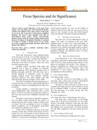
Edge Detection <strong>of</strong> Synthetic Image Using GHM Multiwavelet TransformM s f(x,y)- modulus <strong>of</strong> the wavelet <strong>transform</strong>.A s f(x,y)- modulus angle which indicate the directionwhere the signal has the sharpest Variation.After getting the M s f(x,y) and A s f(x,y) the <strong>edge</strong>point is the one that has the locally maximum modulusamong direction A s f(x,y). After a threshold is applied,the <strong>edge</strong> point below modulus will be eliminated andthis can reduce many false <strong>edge</strong> points.B. Non Maximal SuppressionThe purpose <strong>of</strong> this step is to convert the “blurred”<strong>edge</strong>s in the <strong>image</strong> <strong>of</strong> the gradient magnitudes to “sharp”<strong>edge</strong>s. On maxima suppression step makes all <strong>edge</strong>s intoone pixel thick. Each pixel in turn forms the centre <strong>of</strong> anine pixel neighborhood and considers the gradientmagnitudes at the neighborhood boundary in bothdirections perpendicular to the centre pixel. If the pixelunder consideration is not greater than these two values,it will be suppressed. Consider the pixel underconsideration as C and the neighboring pixel in theperpendicular direction as A and B. If M(A)>M(C) orM(B)>M(C) discard the pixel C by setting it to zero. IfM(C)>M(A) and M(C)>M(B) the pixel C is not deletedPixel A and B are deletedC. Hysteresis ThresholdingHysteresis method identifies the strong <strong>edge</strong>s andpreserves the relevant weak <strong>edge</strong>s. In this method twothresholds T H and T L are applied to the output <strong>of</strong> NonMaximal Suppression M nms (x, y). A pixel is calledstrong if M nms (x, y)> T H . A pixel is called weak if M nms(x, y) ≤ T L. Discard the pixel if it is weak and preserve ifit is strong. If the pixel value is greater than T H orbetween T L and T H then quantize it as 1. If the pixelvalue is less than T L then quantize it as 0.Multiwavelet <strong>transform</strong> is applied on original<strong>image</strong>. After applying the one level <strong>multiwavelet</strong><strong>transform</strong> four low frequency subbands and twelve highfrequency subbands are obtained because, the<strong>multiwavelet</strong> have two scaling and two waveletfunction. Apply <strong>edge</strong> <strong>detection</strong> algorithm to the highfrequency subbands since it consists <strong>of</strong> most <strong>of</strong> highfrequency coefficients i.e., both <strong>edge</strong>s and noises. Thenumber <strong>of</strong> levels can be increased depending on therequirement <strong>of</strong> details desired in the <strong>edge</strong>s. Thisalgorithm flow is shown in Fig.2V. EDGE DETECTION USING CANNY EDGE DETECTOR,SWT AND DMWTIn hysteresis thresholding, set the lower thresholdvalue as 0.2 and upper threshold value as 0.5. The thirdand fourth steps involved in canny <strong>edge</strong> detectoralgorithm are employed in high frequency subbands <strong>of</strong>SWT and DMWT decomposition. The same thresholdvalues are used for all the methods and the <strong>edge</strong> mapobtained is shown in the Fig.3.Original Canny SWT DMWT(a) Edge Detection Methods for Lena Image(b)Edge Detection Methods for Square ImageImageDiscrete MultiwaveletTransform(c) Edge Detection Methods for Square Image(Different Intensity)Applying Edge DetectionAlgorithm(d) Edge Detection Methods for Circle Image with noiseFinding <strong>of</strong> <strong>edge</strong>s from detailcoefficientsImage Edge mapFig.2 Algorithm flow <strong>of</strong> Proposed MethodFig.3 Edge map comparison for various methodsThe outputs <strong>of</strong> <strong>edge</strong> <strong>detection</strong> <strong>using</strong> Multiwavelet<strong>transform</strong> provides better result compared to classical<strong>edge</strong> detector canny and SWT wavelet based <strong>edge</strong>detector .401 | P a g e
No. <strong>of</strong> Edge PixelsSindhuja et. al.The proposed algorithm is checked with square<strong>image</strong> <strong>of</strong> size 586X586. All the center squares haveexactly the same intensity. However, they appear to theeye to become darker as the background gets lighter.The algorithm is tested for laboratory generated<strong>synthetic</strong> <strong>image</strong> circle. For a circle <strong>image</strong> with differentgray levels, Gaussian noise with variance 0.01 is addedand <strong>edge</strong> <strong>detection</strong> is computed for this noisy <strong>image</strong> theresults obtained is as shown in Fig.3 (d). From theresults it is known that even though the canny <strong>edge</strong>detector can provide good <strong>edge</strong> localization it is highlysensitive to noise. Edge <strong>detection</strong> <strong>using</strong> DMWT canprovide good <strong>edge</strong> map even in noisy environment.pixels the number <strong>of</strong> missed <strong>edge</strong> pixels can becalculated. From total number <strong>of</strong> <strong>edge</strong> pixels detectedand number <strong>of</strong> correctly detected <strong>edge</strong> pixels the number<strong>of</strong> falsely detected <strong>edge</strong> pixels can be calculated. Theperformance Comparison Chart for 21- Level StepW<strong>edge</strong>s is shown in Fig.5.The FCR value is calculated for each <strong>image</strong> <strong>using</strong>different <strong>edge</strong> <strong>detection</strong> methods and the values aregiven in TABLE III. When FCR value is low then theperformance is good. From the TABLE III, FCR value<strong>of</strong> <strong>multiwavelet</strong> is less so <strong>multiwavelet</strong> providessuperior performance compared to other two <strong>edge</strong><strong>detection</strong> methods.VI.EDGE DETECTION IN SYNTHETIC IMAGEPerformance <strong>of</strong> <strong>multiwavelet</strong> is examined for theclass <strong>of</strong> <strong>synthetic</strong> <strong>image</strong> (21 level step w<strong>edge</strong>) <strong>of</strong> size501 x 501 by FCR calculation. In Synthetic <strong>image</strong>, theideal number <strong>of</strong> <strong>edge</strong> pixels and their correct position isknown in advance. The ideal number <strong>of</strong> <strong>edge</strong> pixel inthe <strong>synthetic</strong> <strong>image</strong> is 3996.Canny Original SWT DMWTFig.4 Edge Map for Synthetic ImageIn canny all the <strong>edge</strong> pixels are not detected. In<strong>edge</strong> <strong>detection</strong> <strong>using</strong> SWT it is able to detect only somethe vertical <strong>edge</strong> pixels, but in <strong>multiwavelet</strong> based <strong>edge</strong><strong>detection</strong> most <strong>of</strong> the ideal <strong>edge</strong> pixels are detected. Theresults for the <strong>synthetic</strong> <strong>image</strong> are as shown in Figure 4.VII. PERFORMANCE COMPARISONA quantitative performance evaluation model,called the false-detected to correct-detected ratio (FCR)model, is proposed for the evaluation <strong>of</strong> <strong>edge</strong> detectors.The FCR model attempts to provide a common groundfor the quantitative performance evaluation andcomparison between different <strong>edge</strong> <strong>detection</strong> schemes.The Synthetic <strong>image</strong> is taken from USC-SIPI databasewhich can be used for modeling and visualizationbecause the true <strong>edge</strong> position is known and thereforequantitative evaluations <strong>using</strong> the False-Correct Ratio(FCR) are possible.False-Correct Ratio = Number <strong>of</strong> falsely detected pixelsNumber <strong>of</strong> correctly-detectedpixelsComparison is given in the TABLE II; by <strong>using</strong>ideal number <strong>of</strong> pixels and correctly detected <strong>edge</strong>Fig.5 Performance Comparison Chart for 21- Level Step W<strong>edge</strong>TABLE II: COMPARISON OF DMWT WITH SWT AND CANNY EDGEDETECTORImage21-levelstepw<strong>edge</strong>CircleNo. <strong>of</strong>IdealEdgepixels3996814EdgeDetectorTotalno. <strong>of</strong><strong>edge</strong>pixelsdetectedNo. <strong>of</strong>correctlydetected<strong>edge</strong>pixelsNo. <strong>of</strong>missed<strong>edge</strong>pixelsNo. <strong>of</strong>falselydetected<strong>edge</strong>pixelsCanny 3971 2164 1832 1807SWT 4703 828 3168 3875DMWT4661 3767 229 894Canny 804 16 798 788SWT 318 12 802 306DMWT634 222 592 412TABLE III: FCR CALCULATION FOR DIFFERENT EDGE DETECTIONMETHOD402 | P a g e
Edge Detection <strong>of</strong> Synthetic Image Using GHM Multiwavelet TransformImage21-level stepw<strong>edge</strong>CircleVIII.Edge FCRDetectorCanny 0.464SWT 4.67DMWT 0.049Canny 49.25SWT 25.5DMWT 1.85CONCLUSIONA <strong>multiwavelet</strong> based <strong>edge</strong> <strong>detection</strong> algorithmwas proposed, which combines the merit <strong>of</strong> satisfyingsymmetry and orthogonality property simultaneouslyand uses multiple scaling and wavelet function. Fromthe experimental results it is observed that the proposedmethod showed satisfying performance than scalarwavelet and canny <strong>edge</strong> detector.The <strong>multiwavelet</strong>s can better capture the sharp<strong>edge</strong>s and geometric patterns that occur in the <strong>synthetic</strong><strong>image</strong>. For natural <strong>image</strong>s that contain both low andhigh frequency areas, <strong>multiwavelet</strong>s with shufflinggenerally give performance that is competitive to scalarwavelets.Processing, Vol 48, No.1, pp 184-191, 2000.[12] Sharma A, „Spatial Data Mining for Drought Monitoring: AnApproach Using temporal NDVI and Rainfall Relationship‟Thesis, submitted to the International Institute for GeoinformationScience and Earth Observation, 2006.[13] Sundhakar R. and Jayaraman S.”Fingerprint compression <strong>using</strong><strong>multiwavelet</strong>s”, International Journal <strong>of</strong> Signal Processing, pp-78-87, 2006.[14] Zhang S. Q., Xu X. H, Lv J. T, Zang and He N.,“An ImprovedApproach to Image De- Noising Based on Multiwavelet andThreshold”, Journal <strong>of</strong> Physics: Conference Series 48, pp 412–416.REFERENCES[1] Anand.S,Thivya.T,Jeeva.S,” Edge Detection <strong>using</strong> DirectionalFilter Bank”, International Journal <strong>of</strong> Applied InformationSystems (IJAIS) – ISSN: 2249-0868,Volume 1– No.4,2012.[2] Ellinas J.N. “A Robust wavelet-Based watermarking algorithm<strong>using</strong> Edge Detection”, Proceedings <strong>of</strong> world academy <strong>of</strong>science, engineering and technology, 2007,Vol 25, pp 438-443.[3] Fleet P.J.V., Discrete Wavelet Transformations: AnElementary Approach with Applications, A John Wiley &Sons Publication, Second Edition, 2008.[4] Ghouti L., Bouridane A., Ibrahim M.K. and Boussakta.S.”Digital Image Watermarking Using BalancedMultiwavelets”, IEEE Transactions on signal Processing,2006, Vol 54, No. 4, pp 1519-1535.[5] Gonzalez R.C. and Woods R. E,Digital ImageProcessing,Upper Saddle River, NJ: Prentice-Hall, ThirdEdition,2007.[6] Goudarzi M., Taheri.A., Pooyan M., Mahboobi R.“Multiwavelet and Biological Signal Processing”, InternationalJournal <strong>of</strong> Information Technology, Vol 2 , No. 4, pp 264-272,2004.[7] Kim J.H., Kim H.Y. and Lee Y.S. “A novel method <strong>using</strong> <strong>edge</strong><strong>detection</strong> for signal extraction from cDNA microarray <strong>image</strong>analysis”, Experimental and molecular medicine,2001, Vol 33,No. 2, pp 83-88.[8] Kumar S., Ong S.H., Ranganath S. and Chew F.T,”ALuminance- and Contrast- Invarient Edge-SimilarityMeasure”, IEEE Transactions on Pattern Analysis andMachine Intelligence, Vol 28, No.12, pp 2042-2048,2006.[9] Martin M.B and Bell A.E, “New Image CompressionTechniques Using Multiwavelets and Multiwavelet Packets”,IEEE Transactions on Image Processing, Vol. 10, No. 4, pp-500-510,2001.[10] Nixon M.and Aguado A.S,Feature Extraction and ImageProcessing, Academic press, Linacre House, Jordan Hill, FirstEdition,2002.[11] Selesnick I.W, “Balanced Multiwavelet Bases Based onSymmetric FIR Filters”, IEEE Transactions on Signal403 | P a g e