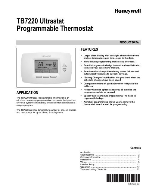
TB7220 Ultrastat Programmable Thermostat - The Energy Conscious
TB7220 Ultrastat Programmable Thermostat - The Energy Conscious
TB7220 Ultrastat Programmable Thermostat - The Energy Conscious

You also want an ePaper? Increase the reach of your titles
YUMPU automatically turns print PDFs into web optimized ePapers that Google loves.
<strong>TB7220</strong> <strong>Ultrastat</strong><strong>Programmable</strong> <strong><strong>The</strong>rmostat</strong>PRODUCT DATAFEATURESAPPLICATION<strong>The</strong> <strong>TB7220</strong> <strong>Ultrastat</strong> <strong>Programmable</strong> <strong><strong>The</strong>rmostat</strong> is aneffortless, seven-day programmable thermostat that providesuniversal system compatibility, precise comfort control and iseasy-to-program.• Large, clear display with backlight shows the currentand set temperature and time—even in the dark.• Menu-driven programming make setup effortless.• Beautiful ergonomic design is smart and sophisticatedto match your customers’ lifestyle.• Real-time clock keeps time during power failures andautomatically updates to daylight savings.• “Saving Changes” notification lets you know when theschedule changes have been saved.• Change reminders let you know when to replace thebatteries.• Holiday Override options allow you to override theprogram schedule, as desired.• Speedy same-schedule programming—no need tocopy multiple days.• Armchair programming allows you to remove thethermostat from the wall for programming.<strong>The</strong> <strong>TB7220</strong> provides temperature control for gas, oil, electricand heat pumps for up to 2 heat, 2 cool systems.ContentsApplication ........................................................................ 1Specifications ................................................................... 2Ordering Information ........................................................ 2Installation ........................................................................ 4Wiring ............................................................................... 5Installer Setup .................................................................. 12Operation .......................................................................... 17Troubleshooting (Table 10) ............................................... 2263-2636-03
<strong>TB7220</strong> ULTRASTAT PROGRAMMABLE THERMOSTATSPECIFICATIONS<strong><strong>The</strong>rmostat</strong> Description: See Table 1.Electrical Ratings: See Table 2.Temperature:Ratings:Operating Ambient:<strong>TB7220</strong>: 0°F to 120°F (-18°C to 49°C).C7089U, C7189U: 5% to 95%.Shipping: -30 °F to 150 °F (-34.4°C to 65.6°C).Display Accuracy: ±1°F (±0.5°C).Setpoint:Range:Heating: 40°F to 90°F (4°C to 32°C).Cooling: 50°F to 99°F (10°C to 37°C).Default Settings: See Table 3.Humidity Ratings (RH, non-condensing):<strong>TB7220</strong> <strong><strong>The</strong>rmostat</strong>: 5% to 90%.C7089U, C7189U: 5% to 95%.FeaturePoweringmethodsSystem types(up to2 heat/2 cool)ChangeoverSystem settingFan settingTable 1. <strong><strong>The</strong>rmostat</strong> Description.Description• Battery only• 24 Vac only• 24 Vac with battery backup• Gas or electric heat with air conditioning• Warm air, hot water, high-efficiencyfurnaces, and heat pumps• Heat only• Heat only with fan• Cool onlyManual or Auto changeover selectableHeat-Off-Cool-AutoAuto-OnTable 2. Electrical RatingsTerminalVoltage(50/60 Hz) Running CurrentW (Heating) 20 - 30 Vac 0.02 - 1.0AY (Cooling) 20 - 30 Vac 0.02 - 1.0AG (Fan) 20 - 30 Vac 0.02 - 0.60AORDERING INFORMATIONTable 3. <strong>Energy</strong>-saving Default Program Settings.ScheduleSetpointsPeriod Time HeatCoolOcc1 8:00am 70°F (21°C) 75°F (24°C)Unocc1 10:00pm 55°F (10°C) 85°F (29.5°C)Occ2 — — —Unocc2 — — —Cycle Rates (at 50% Load):Heating: Selectable 1 - 12 cycles per hour.Cooling: Selectable 1 - 6 cycles per hour.Interstage Differential:Droopless control. Once the first stage is running at 90% load,the thermostat energizes the second stage.Cool Indication: Displays “Cool On” when Cool is activated.Heat Indication: Displays “Heat On” when Heat is activated.Auxiliary Heat Indication: Displays “Aux. Heat On” whenAuxiliary Heat is activated.Clock Accuracy: ±1 minute per month.Finish:TB7000: Premier White® color.C7189U Wall Mount Remote Indoor Sensor: Premier White®color.T7770A Wall Mount Remote Indoor Sensor: Premier White®color.Batteries:Two replaceable AA alkaline batteries: Power thermostat when24 Vac common is not used.Non-replaceable lithium battery with ten-year life: Under normalconditions holds calendar and time settings.NOTE:Alkaline batteries keep calendar and time if lithiumbattery is no longer functional.Resistance Characteristics of Remote Sensors:C7089U Outdoor Sensor: 10K ohm NTC.C7189U Remote Indoor Sensor: 10K ohm NTC.C7772 Flush-Mount Remote Indoor Sensor: 20K ohm NTC.T7770A1006 Wall-Mount Remote Indoor Sensor: 20K ohmNTC.T7770A3002 Wall-Mount Remote Indoor Sensor: 10K ohmNTC.When purchasing replacement and modernization products from your TRADELINE® wholesaler or distributor, refer to theTRADELINE® Catalog or price sheets for complete ordering number.If you have additional questions, need further information, or would like to comment on our products or services, please write orphone:1. Your local Honeywell Automation and Control Products Sales Office (check white pages of your phone directory).2. Honeywell Customer Care1985 Douglas Drive NorthMinneapolis, Minnesota 55422-4386In Canada—Honeywell Limited/Honeywell Limitée, 35 Dynamic Drive, Toronto, Ontario M1V 4Z9.International Sales and Service Offices in all principal cities of the world. Manufacturing in Australia, Canada, Finland, France,Germany, Japan, Mexico, Netherlands, Spain, Taiwan, United Kingdom, U.S.A.63-2636—03 2
<strong>TB7220</strong> ULTRASTAT PROGRAMMABLE THERMOSTATCalibration (<strong>TB7220</strong>, C7089U, C7189U, T7770A):No field calibration required.Mounting Means:<strong>TB7220</strong>: Direct wall-mount using mounting screws andanchors provided. Fits standard vertical or horizontal2 in. x 4 in. junction box.C7089U: Mounts outside of living space with mounting clip andscrews provided.C7189U, T7770A: Mounts directly on the wall using mountingscrews and anchors provided. Fits a vertical 2 x 4 in. junctionbox.LEVEL1BRACKETLEVELUP6-7/8 IN. (175 MM)Cover Plate:32003796-001 Cover Plate is used to cover marks left on thewall by the old thermostat.5 IN.(127 MM)22Dimensions:<strong>TB7220</strong> <strong><strong>The</strong>rmostat</strong>: See Fig. 1.C7089U Outdoor Sensor Mounting Clip: See Fig. 3.C7189U Remote Indoor Sensor: see Fig. 5.T7770A: See Fig. 4.32003796-001 Cover Plate: See Fig. 2.MEDIUM COVER PLATE8-5/16 IN. (211 MM)UP6 IN.(152 MM)226 (152)THERMOSTATAND WALLPLATE1-3/8(35)12LARGE COVER PLATEBRACKET FOR MOUNTING ON JUNCTION BOX NOT INCLUDEDWITH COVER PLATE.USE BOTTOM MOUNTING HOLES.M13669Fig. 2. 32003796-001 Cover Plate dimensions in in. (mm).3-3/4(95)1-1/2 (38)M24100Fig. 1. <strong>TB7220</strong> <strong><strong>The</strong>rmostat</strong>dimensions in in. (mm).M4488Fig. 3. C7089U Outdoor Sensor Mounting Clipdimensions in in. (mm).3 63-2636—03
<strong>TB7220</strong> ULTRASTAT PROGRAMMABLE THERMOSTATKNOCKOUTS FOREUROPEAN APPLICATIONS2-3/8(60)STANDARDUTILITYCONDUITBOX (2 X 4)MOUNTINGHOLES5-1/16(128)CAUTIONElectrical Shock or Equipment Damage Hazard.Can shock individuals or short equipmentcircuitry.Disconnect power supply before installation.Select <strong><strong>The</strong>rmostat</strong> LocationSelect a location for the thermostat about 5 ft (1.5m) above thefloor in an area with good air circulation at averagetemperature. See Fig. 6.2-3/8 (60)3-3/16 (80)15/16(23)M24101Fig. 4. T7770A dimensions in in. (mm).YESNONONO5 FEET[1.5 METERS]4-5/8(117)M22258Fig. 6. Select thermostat location.M241022-3/4 (70)FRONT VIEW1-1/8(29)SIDE VIEWDo not install the thermostat where it can be affected by:— Drafts or dead spots behind doors and in corners.— Hot or cold air from ducts.— Radiant heat from sun or appliances.— Concealed pipes and chimneys.— Unheated (uncooled) areas such as an outside wall behindthe thermostat.Fig. 5. C7189U Indoor Sensor dimensions in in. (mm).MERCURY NOTICEIf this control is replacing a control that containsmercury in a sealed tube, do not place your oldcontrol in the trash. Dispose of properly.Separate Wallplate from <strong><strong>The</strong>rmostat</strong>1. Separate the wallplate from the thermostat. See Fig. 7.WALLPLATEWIRE HOLEContact your local waste management authorityfor instructions regarding recycling and the properdisposal of an old control.INSTALLATIONWhen Installing this Product...1. Read these instructions carefully. Failure to follow themcould damage the product or cause ahazardous condition.2. Check ratings given in instructions and on the product toensure the product is suitable for your application.3. Installer must be a trained, experienced servicetechnician.4. After installation is complete, check out productoperation as provided in these instructions.63-2636—03 4THERMOSTATM22267Fig. 7. Separate wallplate from thermostat.
<strong>TB7220</strong> ULTRASTAT PROGRAMMABLE THERMOSTATInstall Wallplate (See Fig. 8)Mount the thermostat horizontally on the wall:1. Pull the wires through the wire hole on the wallplate.2. Position the wallplate on the wall with the arrow pointingup. Level the wallplate for appearance only.3. Use a pencil to mark the mounting holes.4. Remove the wallplate from the wall and drill two 3/16 in.holes in the wall (if drywall) as marked. For firmermaterial such as plaster, drill two 7/32 in. holes. Tap thewall anchors (provided) into the drilled holes until flushwith the wall.5. Pull the wires through the wire hole on the wallplate andposition the wallplate over the wall anchors.6. Insert the mounting screws into the wall anchors andtighten.WALLWIRES THROUGH WALLAND WIRE SLOTWALLANCHORS (2)NOTES:— Refer to Table 5 for terminal designationdescriptions.— See Fig. 12 through 21 for wiring diagrams forspecific equipment applications.1. Select set of terminal identifications that correspond toyour system type (conventional or heat pump). See Fig. 9.CGYO/BRCR1HEAT PUMPCONVENTIONALCGYWRCR1W2Y2S1S2SCREWTERMINALSFACTORY INSTALLED JUMPER.W1Y2S1S2M24015Fig. 9. Terminal identifications for system type.MOUNTINGHOLES2. Loosen screw terminals used for the application.3. Insert the wires into the terminal block and tighten eachscrew terminal. See Fig. 10.MOUNTINGSCREWS (2)M13665Fig. 8. Install wallplate.WIRINGCAUTIONElectrical Shock Hazard.Can cause electrical shock or equipment damage.Disconnect power supply before connecting wiring.IMPORTANT— All wiring must agree with applicable codes,ordinances and regulations.— Use 18 gauge thermostat wire. Shielded cable is notrequired.WIRE HOLEM13666Fig. 10. Insert wires into terminal block.4. Push excess wire back into the wall opening and restrictwires to the shaded area. See Fig. 11.5. Plug the wall opening with nonflammable insulation toprevent drafts from affecting the thermostat.5 63-2636—03
<strong>TB7220</strong> ULTRASTAT PROGRAMMABLE THERMOSTATWIREWALL OPENINGSHADED AREAFig. 11. Restrict wires to shaded area of wire hole.Table 4. Wiring Diagrams.WALLPLATEM22266System TypeWallplate TerminalIdentificationsWiring DiagramFigureStandard Heat/Cool Conventional 12, 13Heat Only Conventional 14Cool only Conventional 15Standard Multistage Conventional 16, 17up to 2 Heat/2 CoolHeat Pump Heat Pump 18, 19(No Auxiliary Heat)Heat Pump Heat Pump 20, 21(with Auxiliary Heat)Multiple T7770A — 26, 27, 28SensorsMultiple C7189USensors— 29TerminalDesignationRc(see Note 1)R(see Note 1)YC(see Note 2)WGW2Y2O/B(see Note 3)Table 5. Terminal Designation Descriptions.DescriptionPower for cooling—connect to secondary sideof cooling system transformer.Power for heating—connect to secondary sideof heating system transformer.Compressor output.Common wire from secondary side of coolingsystem transformer.Heat relay.Fan relay.Second stage heat relay.Second stage cooling.Changeover valve for heat pumps.S1Optional outdoor or indoor remote sensor.(See Note 5)S2Optional outdoor or indoor remote sensor.(See Note 5)NOTES:1. When used in a single-transformer system, leavemetal jumper wire in place between Rc and R. Ifused on a two-transformer system, remove metaljumper wire between Rc and R.2. Common wire is optional when thermostat is usedwith batteries. When using separate transformersfor heating and cooling, the common must comefrom the cooling transformer.3. If thermostat is configured for a heat pump in theInstaller Setup, configure changeover valve forcool (O-factory setting) or heat (B).63-2636—03 6
<strong>TB7220</strong> ULTRASTAT PROGRAMMABLE THERMOSTATConventional System Wiring1L1(HOT)L224 VAC2CGYWRCR3W2Y2S1S21L1(HOT)L224 VAC23CGYWRCRW2Y2S1S2HEAT RELAYCOMPRESSOR CONTACTORFAN RELAYOUTDOOR/INDOORTEMPERATURESENSORHEAT RELAYOUTDOOR/INDOORTEMPERATURESENSOR1POWER SUPPLY. PROVIDE DISCONNECT MEANS AND OVERLOADPROTECTION AS REQUIRED.12POWER SUPPLY. PROVIDE DISCONNECT MEANS AND OVERLOADPROTECTION AS REQUIRED.FACTORY INSTALLED JUMPER.23FACTORY INSTALLED JUMPER.WHEN USING BATTERIES, THE 24V COMMON CONNECTIONIS OPTIONAL.M24016Fig. 12. Typical wiring of single transformer 1H/1C system.3 WHEN USING BATTERIES, THE 24V COMMON CONNECTION ISOPTIONAL.M24018Fig. 14. Typical hookup of heat-only system.1L1(HOT)L2COOLINGTRANSFORMER1L1(HOT)24 VACL2HEATINGTRANSFORMER24 VACFAN RELAYCOMPRESSOR CONTACTOR2HEAT RELAYC 3GYWRCRW2Y2S1S2OUTDOOR/INDOORTEMPERATURESENSOR1L1(HOT)L212324 VACFAN RELAY2OUTDOOR/INDOORTEMPERATURESENSORPOWER SUPPLY. PROVIDE DISCONNECT MEANS AND OVERLOADPROTECTION AS REQUIRED.FACTORY INSTALLED JUMPER.CGYWRCRCOMPRESSOR CONTACTORWHEN USING BATTERIES, THE 24V COMMON CONNECTIONIS OPTIONAL.3W2Y2S1S2M24019123POWER SUPPLY. PROVIDE DISCONNECT MEANS AND OVERLOADPROTECTION AS REQUIRED.REMOVE FACTORY INSTALLED JUMPER.WHEN USING BATTERIES, THE 24V COMMON CONNECTIONIS OPTIONAL. WHEN USED, THE COMMON MUST CONNECTTO THE COOLING TRANSFORMER SECONDARY.M24017Fig. 15. Typical hookup of cool-only system.Fig. 13. Typical hookup of dual transformer 1H/1C system.7 63-2636—03
<strong>TB7220</strong> ULTRASTAT PROGRAMMABLE THERMOSTAT1L1(HOT)L224 VAC2CGYWRCR3W2Y2S1S21L1(HOT)24 VACL2COOLINGTRANSFORMER2C 3GYWRCRW2Y2S1S2123COOL RELAY 1FAN RELAYHEAT RELAY 1POWER SUPPLY. PROVIDE DISCONNECT MEANS ANDOVERLOAD PROTECTION AS REQUIRED.FACTORY INSTALLED JUMPER.COOL RELAY 2OUTDOOR/INDOORTEMPERATURESENSORHEAT RELAY 2WHEN USING BATTERIES, THE 24V COMMON CONNECTIONIS OPTIONAL.M24020Fig. 16. Typical hookup of single transformer multistagesystem (up to 2H/2C).1L1(HOT)L2HEATINGTRANSFORMER12324 VACCOOL RELAY 1FAN RELAYHEAT RELAY 1COOL RELAY 2POWER SUPPLY. PROVIDE DISCONNECT MEANS ANDOVERLOAD PROTECTION AS REQUIRED.REMOVE FACTORY INSTALLED JUMPER.OUTDOOR/INDOORTEMPERATURESENSORHEAT RELAY 2WHEN USING BATTERIES, THE 24V COMMON CONNECTIONIS OPTIONAL. WHEN USED, THE COMMON MUST CONNECTTO THE COOLING TRANSFORMER SECONDARY.M24022Fig. 17. Typical hookup of dual transformer multistagesystem (up to 2H/2C).Heat Pump System WiringL1(HOT)L2124 VAC4CGYO/BRCR23W1Y2S1S2L1(HOT)L2124 VAC4CGYO/BRCR23W1Y2S1S2CHANGEOVER VALVECOMPRESSOR CONTACTORFAN RELAYOUTDOOR/INDOORTEMPERATURE5SENSORFAN RELAYCHANGEOVER VALVECOMPRESSOR 1 COMPRESSOR 2OUTDOOR/INDOORTEMPERATURESENSOR 512345POWER SUPPLY. PROVIDE DISCONNECT MEANS AND OVERLOADPROTECTION AS REQUIRED.FACTORY INSTALLED JUMPER.WHEN USING BATTERIES, THE 24V COMMON CONNECTIONIS OPTIONAL."O/B" TERMINAL SET TO CONTROL AS EITHER "O" OR "B"IN THE INSTALLER SETUP.OPTIONAL OUTDOOR OR INDOOR REMOTE SENSOR.WIRES MUST HAVE A CABLE SEPARATE FROM THETHERMOSTAT CABLE.M2402112345POWER SUPPLY. PROVIDE DISCONNECT MEANS AND OVERLOADPROTECTION AS REQUIRED.FACTORY INSTALLED JUMPER.WHEN USING BATTERIES, THE 24V COMMON CONNECTIONIS OPTIONAL."O/B" TERMINAL SET TO CONTROL AS EITHER "O" OR "B"IN THE INSTALLER SETUP.OPTIONAL OUTDOOR OR INDOOR REMOTE SENSOR.WIRES MUST HAVE A CABLE SEPARATE FROM THETHERMOSTAT CABLE.M24023Fig. 18. Typical hookup of single-stage heat pump with noauxiliary heat (1H/1C).Fig. 19. Typical hookup of multistage heat pump with noauxiliary heat (2H/2C).63-2636—03 8
<strong>TB7220</strong> ULTRASTAT PROGRAMMABLE THERMOSTATL1(HOT)L21123424 VACCHANGEOVER VALVECOMPRESSOR CONTACTORFAN RELAYCGY4 O/BRCRPOWER SUPPLY. PROVIDE DISCONNECT MEANS AND OVERLOADPROTECTION AS REQUIRED.FACTORY INSTALLED JUMPER.2WHEN USING BATTERIES, THE 24V COMMON CONNECTIONIS OPTIONAL."O/B" TERMINAL SET TO CONTROL AS EITHER "O" OR "B"IN THE INSTALLER SETUP.3W1Y2S1S2OUTDOOR/INDOORTEMPERATURE5SENSORAUXILIARY HEAT RELAYPOWER THE THERMOSTATYou can choose from three methods to power the thermostat:• Batteries only (AAA alkaline).• 24 Vac direct connection only.• 24 Vac direct connection with battery backup (AAA alkaline).Wiring 24 Vac Common• Single-Transformer System—Connect the common side ofthe transformer to the C screw terminal of the thermostatwallplate. Leave the metal jumper wire in place between Rcand R.• Two-Transformer System—Connect the common side ofthe cooling transformer to the C screw terminal of thethermostat wallplate. Remove the metal jumper wirebetween Rc and R.Installing Batteries1. Install two AA alkaline batteries on the back of the thermostatas marked. See Fig. 22.5OPTIONAL OUTDOOR OR INDOOR REMOTE SENSOR.WIRES MUST HAVE A CABLE SEPARATE FROM THETHERMOSTAT CABLE.M24024BATTERIES (2)BATTERY HOLDERFig. 20. Typical hookup of single-stage heat pump withauxiliary heat (2H/1C).L1(HOT)L2124 VAC4CGYO/BRCR3W1Y2S1S22 M22259BACK OF THERMOSTAT123CHANGEOVER VALVECOMPRESSOR 1FAN RELAYCOMPRESSOR 2POWER SUPPLY. PROVIDE DISCONNECT MEANS AND OVERLOADPROTECTION AS REQUIRED.FACTORY INSTALLED JUMPER.OUTDOOR/INDOORTEMPERATURE5SENSORAUXILIARY HEAT RELAYWHEN USING BATTERIES, THE 24V COMMON CONNECTIONIS OPTIONAL.Fig. 22. Installing batteries.2. Locate and remove tab labeled Remove. See Fig. 23.IMPORTANTThis tab must be removed in order to set the real-timeclock.REMOVETAB45"O/B" TERMINAL SET TO CONTROL AS EITHER "O" OR "B"IN THE INSTALLER SETUP.OPTIONAL OUTDOOR OR INDOOR REMOTE SENSOR.WIRES MUST HAVE A CABLE SEPARATE FROM THETHERMOSTAT CABLE.M24025REMOVE DURINGINSTALLATIONFig. 21. Typical hookup of multistage heat pumpwith auxiliary heat (3H/2C).REMOVE DURINGINSTALLATIONM24103Fig. 23. Remove tab labeled REMOVE from thermostatback.9 63-2636—03
<strong>TB7220</strong> ULTRASTAT PROGRAMMABLE THERMOSTATLocate and Mount C7089U OutdoorTemperature Sensor (Optional)Mount the sensor where (see Fig. 24):• cannot tamper with settings.• there is good air circulation.• it can measure true outdoor ambient temperature.• surface is flat.• wire distance between C7089U and thermostat is less than200 feet.Do not mount the sensor:• in direct sunlight.• where hot or cold air blows on the sensor. Discharge linefrom an outdoor compressor unit, vent or fan causesinaccurate temperature readings.• where snow, ice or debris can cover it.Use the following steps to mount the sensor:1. Remove the sensor from the mounting clip.2. Mark the area on the location selected for mounting thesensor mounting clip.3. Mount the clip.Wire C7089U Outdoor SensorCAUTIONElectrical Interference (Noise) Hazard.Can cause erratic system operation.Keep wiring at least one foot away from large inductiveloads such as motors, line starters, lighting ballasts andlarge power distribution panels.Use shielded cable to reduce interference whenrerouting is not possible.1. Wire C7089U Outdoor Sensor to S1 and S2 terminals onthe thermostat. If leadwire provided is not long enough(60 in.), run a cable to a hole at C7089U location.a. Using color-coded, 18-gauge thermostat wire isrecommended. For example of general wiring ofC7089U, see Fig. 25.2. Mount C7089U in its mounting clip.3. Plug wiring hole using nonhardening caulk or putty.1C7089WIRING HOLETHROUGHSTRUCTURE212USE APPROPRIATE MOUNTING MEANS FOR THETYPE OF STRUCTURE.PLUG WIRING HOLE WITH NON-HARDENING CAULKOR PUTTY.M13664Fig. 25. Wire C7089U Outdoor Sensor to the thermostat.Locate and Mount T7770A or C7189U RemoteIndoor Temperature Sensor (Optional)Locate and mount the sensor in the same fashion as thethermostat. See the Select <strong><strong>The</strong>rmostat</strong> Location section.M7514Fig. 24. Typical locations for C7089U Outdoor Sensor.Consider the following as well:1. Be sure wire distance between sensor and thermostat isless than 200 feet.2. Mark the area on the wall selected for mounting thesensor or junction box.3. Sensor wire must be separate from the thermostat cable.4. Run wire cable to a hole at the selected wall location.5. Pull approximately three inches of wire through theopening.NOTE:Color-coded, 18-gauge wire is recommended.63-2636—03 10
<strong>TB7220</strong> ULTRASTAT PROGRAMMABLE THERMOSTATWire Indoor SensorCAUTIONElectrical Interference (Noise) Hazard.Can cause erratic system operation.Keep wiring at least one foot away from large inductiveloads such as motors, line starters, lighting ballasts andlarge power distribution panels.1. Check Installer Setup Number (ISU) 340 to ensure it isset to the desired value. (See Table 6.)2. Wire sensor to S1 and S2 thermostat terminals.3. Push excess wire back into the hole. Plug the hole usingnonhardening caulk, putty or insulation to prevent draftsfrom affecting performance.4. Remove sensor cover.5. Mount sensor to the wall or junction box using thescrews and anchors provided.6. Level the sensor for appearance only. Device functionscorrectly even when not level.7. Install sensor cover.Sensor Wiring for Temperature AveragingT7770A1006TT7770A1006TS1TTSUBBASEFig. 28. Wiring two T7770A1006 (20K ohm) Sensors andone T7770A3002 (10K ohm) sensor to provide atemperature averaging networkT4T3T7770A30021 THE T7770A3002 IS A 10K OHM SENSOR. M22934S21T7770ASUBBASES1 S2T7770A1C7189C7189W2Y2AS1S2TTTTC7189C7189T7770AT7770ATTTT1WIRES MUST HAVE A CABLE SEPARATE FROMTHE THERMOSTAT CABLE.M13667Fig. 29. Wiring four C7189U (10K ohm) Sensors to providea temperature averaging network.M22831Fig. 26. Wiring four T7770A1006 (20K ohm) Sensors.SUBBASES1 S2SET CALENDAR AND TIMEThis thermostat is designed to, under normal use,automatically keep current time and day in memory for up toten years once the calendar is set. <strong>The</strong>re are two ways to setthe calendar for this thermostat:T4T3T4T3Setting Calendar Once FunctioningSee steps 1 through 4, in the Advanced Settings section, to setyear, month and day.111T7770A3002 T7770A3002THE T7770A3002 IS A 10K OHM SENSOR.M22933Setting Calendar When First PoweredWhen first powered, the thermostat proceeds through asequence of screens to set the calendar.— When first powered, the thermostat proceeds through asequence of screens to set the calendar. See Fig. 30.Fig. 27. Wiring two T7770A3002 (10K ohm) Sensors toprovide a temperature averaging network.11 63-2636—03
<strong>TB7220</strong> ULTRASTAT PROGRAMMABLE THERMOSTATMONTH YEAR DAYTueUP AND DOWNBUTTONSCHANGESMONTH,DAY ANDYEAR3. <strong>The</strong> Setup Number displays to the center of the screen.It is a four-digit code beginning with zero. <strong>The</strong> currentsetting is displayed to the right.NOTE:To cycle through the Setup Numbers, press the up ordown arrow.DeSelect DaySystem & FanFanUseEditScheduleGO BACK BUTTONGOES BACK TO LAST SETTINGViewClock & MoreDONEBUTTONADVANCESTO TIMESETTINGSCREENNEXT BUTTONADVANCE TO NEXT SETTINGM24104TueAMSystem Auto Fan AutoSystem & Fan Schedule Clock & MoreFig. 30. Setting calendar when thermostat is first powered.UP AND DOWN BUTTONSCHANGES TIMEM24106Fig. 32. Entering Installer Setup.ViewClock & MoreUser Settings (Simple Set)Access to the user settings is obtained as follows:1. From the main screen, press SYSTEM.2. Press and hold the center key approximately five seconds.3. <strong>The</strong> Setup Number displays to the center of the screen.It is a four-digit code beginning with zero. <strong>The</strong> currentsetting is displayed to the right.DONE BUTTONADVANCES TO HOME SCREENM24105NOTE:To cycle through the Setup Numbers, press the up ordown arrow.Fig. 31. Setting time when thermostat is first powered.INSTALLER SETUPAdvanced Settings<strong>The</strong> thermostat has advanced settings to match the HVACsystem. <strong>The</strong>se settings can be adjusted to match specificneeds.System Auto Fan AutoFanUseEditSystem & Fan<strong>The</strong>re are two different groups of settings:— A complete set designed for the installation use.— A simple set to limit accessibility for typical users.M24107Installer Settings (Complete Set)Access to the installer settings is obtained as follows:1. From the main screen, press SYSTEM.2. Press and hold the two keys on either side of the centerkey for approximately five seconds. (See Fig. 32.)Fig. 33. Entering User Setup.63-2636—03 12
<strong>TB7220</strong> ULTRASTAT PROGRAMMABLE THERMOSTATINSTALLER SETUP NUMBERS (ISU), SETTINGS, AND TESTS (TABLE 6)Use the Installer System Test to test the heating, cooling andfan. Refer to the latter portion of Table 6.CAUTIONEquipment Damage Hazard.Minimum compressor off time is bypassed duringInstaller System TestAvoid cycling compressor quickly.IMPORTANTUse Installer System Test to test heating, cooling andfan. <strong>The</strong> setting chosen for System Type (ISU 0170)can prevent some System Test Numbers fromappearing.NOTE:Unless otherwise noted, setup items are accessiblethrough only the Installer setup and not the Usersetup.InstallerSetupNumberInstaller SetupNameTable 6. Installer Setup Menu.DefaultSetting All Settings Notes0120 a Date (Year Upper) 20 20—20xxAvailable year range: 2001 - 217821—21xx0130 a Date (Year Lower) 04 00-99 Available year range: 2001 - 21780140 a Date (Month) 6 1-120150 a Date (Day) 15 1-31 (Month Dependent)0160 a Schedule Options 4 0—Non-<strong>Programmable</strong>4—<strong>Programmable</strong>0170 System Selection 8 1—1H/1C Conv2—1H/1C HP3—1H w/o fan4—1H with fan6—1C7—2H/1C HP8—2H/2C Conv9—2H/1C Conv10—1H/2C Conv11—2H/2C HP12—3H/2C HP0180 Heat Fan Operation 0 0—Fossil1—Electric0185 Pre-occupancyPurge Duration0 0—no duration1—one hour2—two hours3—three hours0190 Reversing Valve O/B 0 0—O (O/B On Cool)1—B (O/B On Heat)0220 Cycles Per Hour(CPH) for first stagecompressor0230 CPH for secondstage compressor0240 CPH for first stageconventional heat0250 CPH for secondstage conventionalheat0260 CPH for third StageHeatOnly shown for conventional system with heat stages andfan capability selected. If heat pump is selected, fandefaults to electric.Shown only if system has fan and schedule programmable.Pre-occupancy purge enabled by nonzero duration.Only shown with heat pump system selected.3 1-6 Only shown for system with cool stages. Selection in thisstage changes default CPH of second stage cool.3 1-6 Only shown if two stages of cool selected.5 1-12 Only shown if system is conventional with heat stages.Selection in this stage changes default CPH of secondstage heat.5 1-12 Only shown with at least two stages conventional heat or2H/1C heat pump selected.9 1-12 Only shown if 3H/2C heat pump is selected.a Setting available for modification in both the Installer and User setup modes.13 63-2636—03
<strong>TB7220</strong> ULTRASTAT PROGRAMMABLE THERMOSTATInstallerSetupNumberInstaller SetupName0270 CPH for AuxiliaryHeat0280 ContinuousBacklight9 1-12 Only shown if multi-stage heat pump is selected (heatpump with more heat than cool stages).0 0—No1—Yes0300 Changeover 1 0—Manual1—Auto0310 Deadband 3°F(2°C)0320 a TemperatureIndication Scale0 0—°F1—°C2 (1.5)—2°F (1.5°C)3 (2.0)—3°F (2.0°C)4 (2.5)—4°F (2.5°C)5 (3.0)—5°F (3.0°C)6 (3.5)—6°F (3.5°C)7 (4.0)—7°F (4.0°C)8 (4.5)—8°F (4.5°C)9 (5.0)—9°F (5.0°C)0330 a Daylight Saving 2 0—Disabled1—Enabled (US 1987)2—Enabled (US 2007)3—Enabled (Europe)0340 RemoteTemperature Sensor0350 Heat PumpCompressor Lockout0360 Heat Pump AuxiliaryLockout0535 Temporary OccupiedDuration Limit0 0—None1—Outdoor for Display2—Outdoor for Control3—Remote 10K Indoor4—Remote 20K Indoor0 0—None15(-9.5)—15°F (-9.5°C)20(-6.5)—20°F (-6.5°C)25(-4.0)—25°F (-4.0°C)30(-1.0)—30°F (-1.0°C)35(1.5)—35°F (1.5°C)40(4.5)—40°F (4.5°C)45(7.0)—45°F (7.0°C)0 0—None40(4.5)—40°F (4.5°C)45(7.0)—45°F (7.0°C)50(10.0)—50°F (10.0°C)55(13.0)—55°F (13.0°C)60(15.5)—60°F (15.5°C)3 0—no duration1—one hour2—two hours3—three hours4—four hours0540 a Number of Periods 4 2—2 Periods4—4 Periods0580 MinimumCompressor OffTimeTable 6. Installer Setup Menu. (Continued)DefaultSetting All Settings Notes5 0—Off2—2 minutes3—3 minutes4—4 minutes5—5 minutesAlways shown. If AC power not present the option isoverridden and normal backlight operation occurs.Only shown if system has both heat and cool stages.Only shown if Automatic Changeover SelectedAveraging would not include on-board sensor. It isaccomplished by series/parallel combinations.2 applies only to Heat Pump applications (allowingcompressor lockout while displaying temperature).Only shown for heat pump systems with more heat stagesthan cool selected and remote sensor selection is outdoorfor control.Must enforce a dead band between this and AuxiliaryLockoutOnly shown for heat pump systems with more heat stagesthan cool selected and remote sensor selection is outdoorfor control.Must enforce a dead band between this and Heat PumpCompressor Lockout.0 means no limitDoes not appear if Non-programmable is chosen.Applies to all days of the week. With 2 selected the “CancelPeriod” option does not appear on the display.Only shown if system has cool stages.0600 Heat Temperature 90 40 to 90°F (4 to 32°C) Only shown if system has heat stages.Range Stops0610 Cool TemperatureRange Stops50 50 to 99°F (10 to 37°C) Only shown if system has cool stages.a Setting available for modification in both the Installer and User setup modes.63-2636—03 14
<strong>TB7220</strong> ULTRASTAT PROGRAMMABLE THERMOSTATInstallerSetupNumber0640 a Clock Format 12 12—12 Hour24—24 Hour0650 Extended FanOn time Heat0660 Extended FanOn time Cool0 0—Off90—90 seconds0 0—Off40—40 seconds0670 Keypad Lockout 0 0—Unlocked1—Partial Lockout 12—Partial Lockout 23—Fully Locked0680 Temperature ControlHeat0685 Recovery HeatRamp Rate0690 Temperature ControlCool0695 Recovery CoolRamp Rate0700 Temperature DisplayOffset0710 Restore FactoryDefaults2 1—Less Aggressive2—Standard3—More AggressiveNot displayed with fan set to fossil or with cool-onlysystemsOnly shown if system has cool stages.Unlocked: All functions accessible.Partial 1: Locks all but Holiday, Override, and Up/Down.Partial 2: Locks all but Holiday and Override.Full: Entire interface locked/non-functional.Only shown if system has heat stages.Only integral gains affected. Affects control operation in allcontrol regimes (not just recovery or setpoint change).More Aggressive stops signal prior to reaching the setpoint.(For use with oversized equipment.)5 0-20°F/hour Only shown if system has heat stages.0 disables ramped recovery (step setpoint change at periodstart time)2 1—Less Aggressive2—Standard3—More AggressiveOnly shown if system has cool stages.Only integral gains affected. Affects control operation in allcontrol regimes (not just recovery or setpoint change).More Aggressive stops signal prior to reaching the setpoint.(For use with oversized equipment.)3 0-20°F/hour Only shown if system has cool stages.0 disables ramped recovery (step setpoint change at periodstart time)0 -3 (-1.5)— -3°F (-1.5°C)-2 (-1.0)— -2°F (-1.0°C)-1 (-0.5)— -1°F (-0.5°C)0 (0.0)—0°F (0.0°C)1 (0.5)—1°F (0.5°C)2 (1.0)— 2°F (1.0°C)3 (1.5)—3°F (1.5°C)0 0—No1—YesINSTALLER SYSTEM TEST ITEMSTest 1 Installer TestCool0 0—Off1—Cool Stage 12—Cool Stage 2Test 2Test 3Test 4Installer SetupNameInstaller TestFanInstaller TestHeatInstaller TestAuxiliary HeatTable 6. Installer Setup Menu. (Continued)DefaultSetting All Settings Notes0 0—Off1—Fan On0 0—Off1—Heat Stage 12—Heat Stage 1 and 23—Heat Stage 1,2 and 30 0—Auxiliary Heat Off1—Auxiliary Heat Ona Setting available for modification in both the Installer and User setup modes.This offset applies to both the control temperature and tothe display temperature for indoor sensor (and remoteindoor sensor)Resets all Installer Setup parameters to default values andresets the schedule to default. Retains only calendarsettings and time.NOTE:Press the Done button to exit the Installer System Test.15 63-2636—03
<strong>TB7220</strong> ULTRASTAT PROGRAMMABLE THERMOSTATMAIN SCREENDOWN BUTTONLOWERS TEMPERATURE SETTING ORMAKES SELECTIONS IN OTHER SCREENSUP ARROW BUTTONRAISES TEMPERATURE SETTING ORMAKES SELECTIONS IN OTHER SCREENSSYSTEM & FAN BUTTONSELECTS FAN AUTO OR ONSELECTS HEAT, OFF, COOLAND EM HEATSHOWS CURRENTDAY OF WEEKSystemCoolFan AutoSystem & Fan Schedule Clock & MoreCLOCK &MORE BUTTONSELECTS TIME ANDFURNACE FILTERINFORMATIONFig. 34. Main screen selections.MonSCHEDULE BUTTONSELECTS PROGRAMMINGMODESystem Auto Fan AutoCURRENTTIMESet ToAux Heat OnSystem & Fan Schedule Clock & MoreTEMPERATURESETTINGM24108PROGRAMMINGTable 7 shows default program settings.Table 7. <strong>Energy</strong>-saving Default Program Settings.ScheduleSetpointsPeriod Time HeatCoolOcc1 8:00am 70°F (21°C) 75°F (24°C)Unocc1 10:00pm 55°F (10°C) 85°F (29.5°C)Occ2 — — —Unocc2 — — —Fan SettingsAuto: Fan runs only when heating/cooling system is on.See the Fan Schedule section for more information.On: Fan runs continuously.System SettingsHeat: <strong><strong>The</strong>rmostat</strong> controls the heating system.Off: Both heating and cooling systems are off.Cool: <strong><strong>The</strong>rmostat</strong> controls the cooling system.Auto: <strong><strong>The</strong>rmostat</strong> automatically changes between heat andcool operation, depending on indoor temperature.Programming Heating and Cooling Schedule<strong>The</strong> thermostat can control up to four different scheduleperiods per day:OCC 1: Work arrival time. Period to keep space at acomfortable temperature.UNOCC1: Work exit time. Period to keep space at anenergy-saving temperature.OCC 2: Second occupied period.UNOCC2: Second unoccupied period.NOTE:Available schedule times are at 15-minute intervals.Editing Schedule1. Press MORE2. Press SCHEDULE.3. Press EDIT.4. Press SELECT DAY to select the days you wish toschedule.5. Press NEXT when finished selecting daysCURRENTSYSTEM SETTINGCURRENTFAN SETTINGINDICATESTHERMOSTAT IS"CALLING FORCOOL OR HEAT"M24109NOTES:— Multiple days can be selected.— To skip over a day, press the Up or Down arrowkeys.— Checkmarks appear next to selected days. <strong>The</strong>seare scheduled with identical times and temperatures.Fig. 35. Main screen display.63-2636—03 16
<strong>TB7220</strong> ULTRASTAT PROGRAMMABLE THERMOSTATOPERATIONMonTueWedThuFriSatSunSelect DayNext Step CancelSetting Temperature Overrides<strong>The</strong>re are three temperature override options:— Hold Temperature Until— Override, and—Holiday.HOLD TEMPERATURE UNTILHolds the temperature temporarily until the time set by theuser, or the next scheduled period time.Fig. 36. Initial schedule edit screen.6. OCCUPIED 1 flashes, denoting the period that is aboutto be edited.7. Press NEXT, and the start time for that period flashes.8. Change the start time by pressing the Up and Downarrow keys.9. Press NEXT to edit the heating and cooling setpoints.10. Continue to cycle through the remaining periods andmake changes by pressing the NEXT key.DAYSSELECTEDMonTueWedThuFriGO BACK BUTTONGOES BACK TO THELAST SCHEDULE STEPSCHEDULEPERIODPeriodWake LeaveFig. 37. Screen to edit existing settings.11. When complete, press DONE. SAVING CHANGESappears on the screen to indicate changes are beingsaved to the day(s) modified.12. To exit schedule without saving changes, press CANCELany time.Setting Time1. Press CLOCK.2. Use arrows to set current time.3. Press DONE.AMHeatGo Back Next Step DoneNEXT STEP BUTTONADVANCES PERIOD,TIME,HEAT AND COOL TEMPERATURESM24110HEAT OR COOLTEMPERATURESUP ARROWCHANGES TIMEANDTEMPERATURESDOWN ARROWCHANGES TIMEANDTEMPERATURESDONE BUTTONEXITS AND SAVESCHANGES MADETO SCHEDULEM24111IMPORTANT<strong>The</strong> current day of the week should already be setcorrectly. If not, see the Advanced Settings section toset the day.1. Press the Up or Down arrow next to the temperature toadjust. <strong>The</strong> Hold Until time appears on the screen. <strong>The</strong>time defaults to the next scheduled period start time2. Press NEXT to adjust the time for the thermostat toresume schedule.NOTE:<strong>The</strong> installer setup can limit the length of timefor an override to 1, 2, 3, or 4 hours beyond thecurrent time.3. Press DONE or wait 5 seconds.4. Press CANCEL or SCHEDULE to cancel “Hold TemperatureUntil” and resume the schedule.OVERRIDEChanges temperature setting until the next period takes effect.For use during Unoccupied periods.1. Press OVERRIDE. <strong>The</strong> settings change by default to thenext Occupied period.NOTE:Changes are limited to those allowed by thelockout level.2. Press Up or Down arrow to change the override temperature,and NEXT to adjust override time.HOLIDAYChanges temperature setting for a designated number of days.Press MORE and then HOLIDAY. <strong>The</strong> screen shows “HoldUntil 1 DAYS”.1. Press Up or Down arrow to change the temperaturedesired for the thermostat to override the schedule.2. Press NEXT to change the desired days for the durationof the holiday.3. To cancel the Holiday Override early, press CANCEL.Fan Status Displayed on Main Screen. When the thermostat is running the fan, the fan blade symbolappears next to FAN to indicate the thermostat has the fanon.NOTE:If the thermostat is not controlling the fan—typical formany gas, forced-air heating systems—the fan bladesymbol will not appear even though the fan maybe running.Replacing BatteriesNot all thermostat models require batteries. If the thermostathas batteries, a low battery warning (see Fig. 38) flashes onthe main screen for approximately 30 days.17 63-2636—03
<strong>TB7220</strong> ULTRASTAT PROGRAMMABLE THERMOSTATNOTES:— If batteries are not replaced when the Low Batterywarning is flashing, the LO batt screen displayscontinuously and the thermostat stops operatinguntil batteries are replaced.— <strong>The</strong> thermostat has a low battery indicator.However, it is recommended that the batteries bereplaced once each year. Do this to preventleakage and prevent the thermostat and HVACsystem from shutting down due to lack ofthermostat battery power.WALLPLATETERMINAL SCREW BLOCKPINS ONBACK OFTHERMOSTATM24114Fig. 38. Low battery signal.Replace the batteries as follows:1. Remove the thermostat from the base by pulling itstraight out. (See Fig. 39.)2. Install two new AA alkaline batteries with proper polarization.NOTES:— Always use AA alkaline batteries.— All programming (Schedule, Date and Time)information is retained during battery replacement.3. Place thermostat back on subbase by aligning terminalscrew blocks with the pins on the back of the thermostat.(See Fig. 40.)4. Push the thermostat straight onto the base.WALLM24112Fig. 40. Placing thermostat back onto subbase.Reading Remote Indoor TemperatureIf connected to an installed remote indoor temperature sensor,the thermostat displays the indoor temperature from theremote sensor(s).NOTE:If connected to an installed remote indoor temperaturesensor, the thermostat internal sensor is not used.ONE REMOTE INDOOR SENSOR INSTALLEDIf one remote indoor temperature sensor is used, the screenshowing the Inside temperature reading displays thetemperature at the indoor remote sensor location.MULTIPLE REMOTE INDOOR SENSORS INSTALLEDIf more than one remote indoor sensor is used, the screenshowing the Inside temperature reading displays the averageof all the remote indoor sensors.Reading Outdoor TemperatureIf connected to an outdoor sensor, the thermostat can displaythe Outside temperature.VIEW OUTSIDE TEMPERATUREView the outdoor temperature by pressing MORE until theoutside temperature shows where the Indoor temperature wasdisplayed. <strong>The</strong> word Outdoor will be displayed on the LCD.Fig. 39. Removing thermostat from subbase.M24113Screen LockedPortions of the touch screen interface can be fully or partiallylocked. See the Advanced Settings section for information touse these features. When the thermostat displays LOCKED,the buttons are either fully or partially locked.Fully Locked ScreenIn this mode, the entire interface is locked and not functional.To unlock screen, see the Advanced Settings section. <strong>The</strong>screen continuously displays SCREEN LOCKED.63-2636—03 18
<strong>TB7220</strong> ULTRASTAT PROGRAMMABLE THERMOSTATPartially Locked ScreenWhen partially locked:— Pressing a locked key prompts the screen to indicateSCREEN LOCKED for five to seven seconds.— Pressing an unlocked key with SCREEN LOCKED activeremoves SCREEN LOCKED from the display.PARTIAL LOCKOUT 1This mode locks all keys except HOLIDAY, OVERRIDE, andtemperature Up/Down arrows:— User can change the temperature setpoint, but cannotchange schedule settings.— <strong>The</strong> temporary temperature change lasts until nextscheduled period. <strong>The</strong> screen displays that time.— User can change the temperature setpoint, but cannotchange schedule settings.— Pressing HOLIDAY sets the temperature to the Unoccupiedsetting for the selected period of time. <strong>The</strong> next Occupiedperiod switches back to the program settings.— Pressing OVERRIDE sets the temperature to the Occupiedsetting for the selected period of time. <strong>The</strong> next Unoccupiedperiod switches back to the program settings.— To cancel the temperature override and follow theprogrammed schedule, press CANCEL.— To unlock the screen, see Advanced Settings section.PARTIAL LOCKOUT 2This mode locks all keys except HOLIDAY and OVERRIDE:— Pressing HOLIDAY sets the temperature to the Unoccupiedsetting for the selected period of time. <strong>The</strong> next Occupiedperiod switches back to the program settings.— Pressing OVERRIDE sets the temperature to the Occupiedsetting for the selected period of time. <strong>The</strong> next Unoccupiedperiod switches back to the program settings.— To cancel the temperature override and follow theprogrammed schedule, press CANCEL.— To unlock the screen, see Advanced Settings section.Temperature Recovery<strong>The</strong> thermostat is equipped with a feature to eliminateguesswork when setting a schedule. That is, the user need notknow the amount of time for the HVAC system to bring thespace to temperature (without overshoot) prior to thescheduled time. <strong>The</strong> thermostat manages that automatically.Simply set the program schedule to the desired time to havethe space at comfort temperature. In addition, program thetemperature to this comfort temperature. <strong>The</strong> thermostatactivates the heating or cooling at the proper time to reach thescheduled temperature at the scheduled time.NOTE:<strong>The</strong> setpoint changes gradually to use economicalstages and avoid overshoot.For example—the space will be occupied at 8:00 AM and thedesired temperature is 70°F. Set the OCC 1 period for 8:00 AMand 70°F. <strong>The</strong> thermostat turns on the heat prior to 8:00 AM toraise the temperature to 70°F by 8:00 AM.<strong>The</strong> thermostat provides an alert that the heating or coolingsystem is coming on before a scheduled time by displaying“Recovery” on the screen.Minimum-Off Timer Compressor Protection<strong>The</strong> thermostat has an adjustable Minimum-Off Timer that canbe set from zero to five minutes (Factory Setting—fiveminutes). <strong>The</strong> Minimum-Off Timer can be bypassed throughthe Installer System Test or it can be bypassed permanently bysetting the Minimum-Off Timer to 0 minutes in the InstallerSetup. <strong>The</strong> Minimum-Off Timer is activated after thecompressor turns off:— If the thermostat is system powered (common wire), theMinimum-Off Timer is also activated upon initial startup andafter power interruptions.— If there is a call for cooling or heating during the Minimum-Off Time, the thermostat displays “Wait.”— When the Minimum Off Timer expires, “Cool On” or “HeatOn” (heat pumps only)” appears solidly in the display andthe compressor and fan turn on.Heat Pump Temperature LockoutsDual Fuel Heat Pump and Outdoor TemperatureSensorIn this operation, there is no external fossil fuel kit (dual fuel kit)installed; the thermostat controls this function:1. Choose correct heat pump application in ISU 0170.2. Choose Outdoor Temperature Sensor for Heat PumpTemperature Lockouts Option in ISU 0340.3. Choose appropriate Balance Point Temperature inISU 0350.OPERATION IN HEAT MODE ABOVE BALANCE POINT (OUTDOORTEMPERATURE)When the outdoor temperature is above the selected BalancePoint Temperature (ISU 0350), only the compressor operatesand the fan (G terminal) energizes when the thermostat callsfor heat.OPERATION IN HEAT MODE BELOW BALANCE POINT (OUTDOORTEMPERATURE)When the outdoor temperature is below the selected BalancePoint Temperature (ISU 0350), only the Fossil Fuel (auxiliaryheat) operates and the fan (G terminal) does not energizewhen the thermostat calls for heat.Heat Pump with Auxiliary (Backup) Heat and OutdoorTemperature Sensor1. Choose correct heat pump application in ISU 0170.2. Choose Outdoor Temperature Sensor for ControlOption in ISU 0340.3. Choose Compressor Lockout Temperature inISU 0350.4. Choose Auxiliary Lockout Temperature in ISU 0360.NOTE:<strong>The</strong>re is a 5°F deadband between Compressor andAuxiliary Heat lockout temperaturesOperation in Heat ModeWhen the outdoor temperature is:— Below Compressor Lockout Temperature: only AuxiliaryHeat operates.— Above Auxiliary Lockout Temperature: only the Compressoroperates.— Between the two temperatures: both the Compressor andAuxiliary Heat operate.19 63-2636—03
<strong>TB7220</strong> ULTRASTAT PROGRAMMABLE THERMOSTATOUTDOOR TEMPERATURE5035Fig. 41. Heat Pump Operation with LockoutTemperatures Set.Operating Sequence<strong>The</strong> thermostat energizes specific terminal(s), depending onthe demand for heating, cooling or fan. <strong>The</strong> thermostat screenshows the time, inside temperature, system and fan selections.Additional indicators are shown when the heating, cooling orfan is energized. See Tables 8 and 9 for specificationinformation.Table 8. Sequence of Operation for Conventional Systems.SystemSettingFanSetting Call for ActionEnergizeTerminalsOff Auto — — —Cool Auto — — —Coolor AutoCoolor AutoAuto Stage 1CoolingAuto Stages 1 and 2CoolingScreenMessageY, G Cool OnY, Y2 a , G Cool OnHeat Auto — — —Heator AutoHeator AutoCOMPRESSOR ONLYBOTH COMPRESSOR ANDAUXILIARY HEATAUXILIARY ONLYAuto Stage 1HeatingAuto Stages 1 and 2HeatingAUXILIARYLOCKOUTTEMPERATURECOMPRESSORLOCKOUTTEMPERATUREM19950W, G b Heat OnW, W2 c , G b Heat Ona If Installer Setup System type is set to two stages of cooling.b G energizes only if Installer Setup 0180 is set to Electric.c If Installer Setup System type is set to two stages of heating.Table 9. Sequence of Operation for Heat Pump Systems.SystemSettingFanSetting Call for ActionEnergizeTerminalsScreenMessageOff Auto — O/B a —CoolCoolor AutoAuto Stage 1 Cooling Y, G, O/B a Cool OnStages 1 and 2CoolingY, Y2 b , G,O/B aHeat Auto None O/B a —Heator AutoAuto Stage 1 Heating Y, G, O/B a Heat OnStages 1 and 2HeatingStages 1, 2 and 3HeatingY, W1 c , G,O/B aY, Y2 b ,W1 d , G,O/B aAuxiliaryHeat Ona Configure O/B in Installer Setup. Based on last piece ofequipment called (cooling = O; heating = B).b If Installer Setup System Type is set to 3Heat/2Cool HeatPump with Auxiliary Heat.c If Installer Setup System Type is set to 2Heat/1Cool HeatPump with Auxiliary Heat.d This terminal does not energize if Installer Setup System typeis set to 2 Heat/2 Cool Heat Pump with no Auxiliary Heat.Second Stage Heat and Cool ControlWhile maintaining setpoint, several factors affect when 2ndstage energizes such as load conditions, environmentalconditions, P+I control, and home insulation. <strong>The</strong> second stageenergizes when the thermostat senses 1st stage is running at90% capacity. This operation is droopless control.Temperature Sensor Operation and CheckoutAllow outdoor or indoor temperature sensor to absorb the airfor a minimum of five minutes before taking a reading. See theSensor instructions for more information.NOTE:<strong>The</strong> C7089U, C7189U, and T7770A TemperatureSensors are calibrated at the factory and cannotbe recalibrated in the field.C7089U Outdoor Temperature SensorOperationWhen installed with <strong><strong>The</strong>rmostat</strong> ISU 0340 set to 1 or 2, thethermostat can display outside temperature.CheckoutAllow C7089U Outdoor Sensor to absorb outdoor air for aminimum of twenty minutes before taking a reading.With an accurate thermometer (±1°F [0.5°C]) measure thetemperature at the sensor location, allowing time for thethermometer to stabilize before reading.63-2636—03 20
<strong>TB7220</strong> ULTRASTAT PROGRAMMABLE THERMOSTATTo verify sensor resistance, remove one wire from one of theC7089U 60-in. leadwires. Use an ohmmeter to measure theresistance across the sensor. <strong>The</strong>n compare sensor accuracywith the temperature/resistance curve in Fig. 42.C7189U Remote Indoor Temperature SensorOperationWhen installed with <strong><strong>The</strong>rmostat</strong> ISU 0340 set to 3, the remoteinside temperature is displayed on the <strong><strong>The</strong>rmostat</strong> HomeScreen as Inside Temperature. <strong>The</strong> thermostat internaltemperature sensor is not used.<strong>The</strong> C7189U can be used to provide one remote sensor inputor as a temperature averaging network with multiple C7189USensors connected, as shown in Fig. 29.CheckoutFor best results, allow C7189U Wall Mount TemperatureSensor to absorb the air moving through the room for aminimum of twenty minutes before taking a resistancemeasurement.With an accurate thermometer (±1°F [0.5°C]) measure thetemperature at the sensor location, allowing time for thethermometer to stabilize before reading.To verify sensor resistance, remove one wire from one ofC7189U wiring terminals. Use an ohmmeter to measure theresistance across the sensor. <strong>The</strong>n compare sensor accuracywith the temperature/resistance curve in Fig. 42.RESISTANCE (OHMS)220K190K160K130K100K90K60K30K10K OHM AT77 o F (25 o C)0K-40 -20 0 20 40 60 80 100 120-40 -30 -20 -10 0 10 20 30 40 50TEMPERATURE (DEGREES)o FoCM22823T7770A Remote Temperature SensorOperationWhen installed with <strong><strong>The</strong>rmostat</strong> ISU 0340 set to 3 or 4, theremote inside temperature is displayed on the <strong><strong>The</strong>rmostat</strong>Home Screen as Inside Temperature. <strong>The</strong> thermostat internaltemperature sensor is not used.<strong>The</strong> T7770A can be used to provide one remote sensor inputor as a temperature averaging network with multiple T7770ASensors connected, as shown in Fig. 26 through 28.CheckoutFor best results, allow T7770A Wall Mount TemperatureSensor to absorb the air moving through the room for aminimum of twenty minutes before taking a resistancemeasurement.With an accurate thermometer (±1°F [0.5°C]) measure thetemperature at the sensor location, allowing time for thethermometer to stabilize before reading.To verify sensor resistance, remove one wire from one of thewiring terminals. Use an ohmmeter to measure the resistanceacross the sensor. <strong>The</strong>n verify the sensor accuracy with thetemperature/resistance in Fig. 43.RESISTANCE (OHMS)80K70K60K50K40K30K20K10K30 40 50 60 70 80 90 100 1100 10 20 30 40TEMPERATURE (DEGREES)20K OHM AT77 o F (25 o C)oFoCM5874AFig. 43. 20K ohm sensor resistance versus temperature.Fig. 42. 10K ohm sensor resistance versus temperature.21 63-2636—03
<strong>TB7220</strong> ULTRASTAT PROGRAMMABLE THERMOSTATTROUBLESHOOTING (TABLE 10)Table 10. Troubleshooting.Symptom Possible Cause ActionDisplay does not come on. <strong><strong>The</strong>rmostat</strong> is not being powered. Check for 24 Vac between C and Rc.Check that AAA batteries are installed correctlyand are good.Temperature settings do notchange.Heating or cooling does not comeon.<strong><strong>The</strong>rmostat</strong> is calling for Heat(Heat on) or Cool (Cool on) butno heating or cooling is running.Heat does not turn on (Heat On issolid in the display).<strong>The</strong> upper or lower temperature limits werereached.<strong>The</strong> keypad is fully locked.Check temperature setpoints.Check ISU 0600 and 0610; modify as needed.Check ISU 0670 to change keypad lockedoptions.<strong><strong>The</strong>rmostat</strong> minimum off-time is activated. Wait up to five minutes for the system to respond.System selection is not set to Heat or Cool. Set system Selection to correct position.System type Selection is incorrect. Check ISU 0170 and make sure correct Systemtype is chosen.Heating or cooling equipment is notoperating.Heating equipment failure.Check wiring.Check ISU 0170 and make sure correct systemtype is chosen.Verify operation of equipment in System Testmode.Check for 24 Vac at the equipment on thesecondary side of the transformer between powerand common. If voltage is not present, check theheating equipment to find the cause of theproblem.Cooling does not turn on (CoolOn is solid in the display).Fan does not turn on in a call forheat (electric furnace).Heat pump puts out cool air in theheat mode and warm air in thecool mode.Both the heating and coolingequipment are running at thesame time.Loose or broken wire connection betweenthermostat and heating equipment.Cooling equipment failure.Loose or broken wire connection betweenthermostat and cooling equipment.Fan Control in Heating is set to Gas or OilFurnace (Setting 0180).Changeover Valve (ISU 0190) is notconfigured to match the changeoverrequired by the installed heat pump.<strong>The</strong> heating equipment is not a heat pumpbut the System Type (ISU 0170) is set toHeat Pump.Heating and cooling wires are shortedtogether.Check for 24 Vac between the heat terminal (W)and transformer common. If 24 Vac is present, thethermostat is functional. Check the heatingequipment to find the cause of the problem.Check for 24 Vac between the heat terminal (W)and transformer common. If voltage is notpresent, check wire connection (loose or broken)between the thermostat and the heatingequipment.Check for 24 Vac at the equipment on thesecondary side of the transformer between powerand common. If voltage is not present, check thecooling equipment to find the cause of theproblem.Check for 24 Vac between the cool terminal (Y)and transformer common. If 24 Vac is present, thethermostat is functional. Check the coolingequipment to find the cause of the problem.Check for 24 Vac between the cool terminal (Y)and transformer common. If voltage is notpresent, check the wire connection (loose orbroken) between the thermostat and the coolingequipment.Set Fan Control in Heating to Electric Furnace(Setting 0180).Set Changeover Valve (ISU 0190) to match thechangeover required by the installed heat pump.Set System Type (ISU 0170) to match theinstalled heating and/or cooling equipment.Separate the shorted heating and cooling wires.63-2636—03 22
<strong>TB7220</strong> ULTRASTAT PROGRAMMABLE THERMOSTATTable 10. Troubleshooting. (Continued)Symptom Possible Cause ActionHeating equipment is running inthe cool mode.Heating equipment does not turnoff and heat temperature settingis set below room temperature(Heat On is not in the display).Cannot set the system setting toHeat.Heating equipment is not a heat pump butSystem Type (ISU 0170) is set to HeatPump.Heating equipment is not a heat pump butSystem Type (ISU 0170) is set to HeatPump.System Type (ISU 0170) is set to CoolOnly.Set System Type (ISU 0170) to match theinstalled heating and/or cooling equipment.Set System Type (ISU 0170) to match theinstalled heating and/or cooling equipment.Set System Type (ISU 0170) to match theinstalled heating and/or cooling equipment.Cannot set the system setting toCool.System Type (ISU 0170) is set to HeatOnly or Heat Only with Fan.Set System Type (ISU 0170) to match theinstalled heating and/or cooling equipment.Heat On is not in the display.Cool On is not in the display.Perchlorate MaterialThis thermostat contains a Lithium battery which may containPerchlorate material.<strong>The</strong> following statement is required:Perchlorate Material—special handling may apply.See www.dtsc.ca.gov/hazardouswaste/perchlorateSystem setting is not set to Heat and/ortemperature setting is not set above roomtemperature.System setting is not set to Cool and/or thetemperature setting is not set below roomtemperature.Set the system setting to Heat and set thetemperature setting above the room temperature.Set the system setting to Cool and set thetemperature setting below the room temperature.Wait is in the display. Compressor minimum off timer is active. Wait up to five minutes for the cooling or heating(heat pump) equipment to turn on.“Screen Locked” appears on thescreen and all or some of thekeys do not respond.<strong>The</strong> keypad is fully or partially locked.Check ISU 0670 to change keypad lockedoptions.23 63-2636—03
<strong>TB7220</strong> ULTRASTAT PROGRAMMABLE THERMOSTATAutomation and Control SolutionsHoneywell International Inc. Honeywell Limited-Honeywell Limitée1985 Douglas Drive North 35 Dynamic DriveGolden Valley, MN 55422 Toronto, Ontario M1V 4Z9customer.honeywell.com® U.S. Registered Trademark© 2011 Honeywell International Inc.63-2636—03 M.S. Rev. 03-11