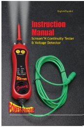
PPH1 Power Probe The Hook Operation Manual
PPH1 Power Probe The Hook Operation Manual
PPH1 Power Probe The Hook Operation Manual
Create successful ePaper yourself
Turn your PDF publications into a flip-book with our unique Google optimized e-Paper software.
Page 4I - Start-Upa) Operating Voltage Source<strong>The</strong> PPH is designed for use in 12 to 48 VDC electrical systemsand comes supplied with a 20 ft., 10-gauge coax cableand 2 heavy-duty battery hook-up clips.b) Connecting to the Vehicle’s Battery(Voltage Source)Connect the red clip to the positive terminal of the vehiclesbattery source and the black clip to negative or ground. <strong>The</strong>PPH start-up tone will sound and the indicator light on the Y-Connector with Battery Clips will illuminate. This tells you thatthe <strong>Hook</strong> is connected correctly and the internal fuse of theY-battery-clip-connector is working properly.c) Y-Connector with Battery Clips<strong>The</strong> Y-Connector with Battery Clips has a safety fuse built intoit. <strong>The</strong> built-in fuse will blow in the event the 10-gauge coaxpower cable gets clamped or pinched in a door or hood causinga short circuit.Note: If the Y-Connector with Battery Clips does not light whenproperly connected to the voltage source, you probably have adamaged 10 gauge coax power cable. It is recommended thatthe cable be inspected and tested before replacing a new Y-Connector with Battery Clips.Contact your distributor or <strong>Power</strong> <strong>Probe</strong>, Inc. for a replacement.Lights up whenconnected to apower source.Y-Connector12 - 48 VDC2 0M5 0 5B A TT 1 2 0d) Auxiliary Ground Lead<strong>The</strong> auxiliary ground lead provides ground to circuits andcomponents that are not already connected to ground. It alsoserves as the negative lead for resistance testing.To test the auxiliary ground lead, contact the probe tip and theauxiliary ground lead together. <strong>The</strong> Green LED on the displayshould light. This shows that the auxiliary ground lead is workingproperly.If the green LED does not illuminate, check the replaceable 25amp fuse in the auxiliary ground lead. <strong>The</strong> fuse is a protectionin the event the lead is inadvertently contacted with batterypositive.e) FlashlightTo replace the fuseremove cover.Green LEDOHM0 0 1HFlashlight is a standard feature on the PPH. <strong>The</strong> bright LEDFlashlight is always ON making it possible to probe underdashboards and in dark areas.Flashlightf) Sleep Mode<strong>The</strong> PPH goes to sleep after 10 minutes of inactivity and youwill see SLEEPING in the display. <strong>The</strong> Flashlight and the LCDbacklight will turn off. To wake it up, just press any button orcontact the probe tip to a circuit.S L E E P I NG
Page 6III Continuedd) <strong>Power</strong> Switch PreferencesTo adjust and set the <strong>Power</strong> Switch Preferenceswhile in PPHM:1. Press SEL once.2. Press D once. Display shows POW SWITCH.3. Press L or R to select the desired <strong>Power</strong> Switch preference:LATCH, PULSE or MOMENT.4. Press SEL to return to PPHM.5. Notice the new <strong>Power</strong> Switch Setting in the preference line.P O W SW I T C HM O ME NTOn_Off<strong>Power</strong> Switch Behaviors when in PPHM:M= Moment: When the <strong>Power</strong> Switch Setting is set to M, batterysource power or ground is supplied to the probe tip whenyou press and hold U(+) or D(–).PressONOn_ReleaseOFFL= Latch: When the <strong>Power</strong> Switch Settings are set to L youcan hold continuous battery positive or ground to the probe tip,by pressing the U(+) or D(–). To release power, press U(+) orD(–) again.P OW SWIT C HLATCHOffPress &ReleaseONPress &ReleaseOFFP= Pulse: When the <strong>Power</strong> Switch Setting is set to P, the PPHwill cycle battery positive or ground to the probe tip by pressingU(+) or D(–).It cycles ON for .5 seconds, then OFF for .5 seconds repeatedly.To stop the power cycling, press U(+) or D(–) again.P OW SW I T C HP U LSEOn_Off.5 sec.5 sec.5 sece) AC Threshold PreferencesPress &ReleaseSTARTPress &ReleaseSTOPTo adjust and set the AC Threshold Preferenceswhile in PPHM:1. Press SEL, once.2. Press D, twice. Display shows AC THRES.3. Press L, or R, to select the desired AC Thresholdpreference: .1, .2, .5, 1, 2, 5, 10, 20, or 50.4. Press SEL to return to PPHM.5. Notice the new AC Threshold Setting in the preference line.A C T H R E S50f) LED Voltage Drop PreferencesTo adjust and set the LED Voltage Drop Preferenceswhile in PPHM:1. Press SEL once.2. Press D, 3 times. Display shows LED V DROP.3. Press R or L, to select the desired Voltage Drop preference:.2, .5, 1, 2, or 3.4. Press SEL to return to PPHM.5. Notice the new LED Voltage Drop Setting in thepreference line.L EDV D R O P5
IV - <strong>Power</strong> <strong>Probe</strong> <strong>Hook</strong> Mode (PPHM)Page 7In PPHM the “Smart Tip Advantage” gives you several new powerful tools to help you fix electricalproblems faster than any other circuit tester in its class. Why?Because it automatically selects the:RIGHT METER and the RIGHT FUNCTION for the RIGHT CIRCUIT condition.a) Voltage Testing in PPHM:Voltage testing is as easy as contacting the probe tip to acircuit and reading the display. <strong>The</strong>re is no need to select thevoltmeter before probing because the PPH does that for youautomatically. <strong>The</strong> PPH also provides both the battery sourcevoltage and the probe tip voltage on the display screen foreasy voltage comparing.Voltage Testing11.8VTo test for voltage in PPHM:1. Take note of the preference parameters in the display.2. Contact the probe tip to a voltage potential.3. Take note of the difference between VOLT and BATT onthe display.If the voltage difference is within the LED Voltage Drop Preferences,the Red LED will light and the HOT SHOT symbol willbe present.If the voltage difference is greater than the LED Voltage DropPreferences, the LED will not light.V OL T 11 8B A T T 1 2 64. Voltage is measured from 0 to 99.9 volts.b) Resistance Testing in PPHM:Resistance testing is as easy as contacting the probe tip toa circuit or a component and reading the display. <strong>The</strong>re is noneed to select the Ohm Meter before probing because thePPH does that for you automatically. It will also auto-range thedecimal point.Resistance Testing100ΩTo test for resistance in PPHM:1. Contact the probe tip to a circuit or component withresistance to ground.Resistance is measured and displayed from 0 to 15 megohms.It is necessary to connect the ground lead to a chassis or othercommon ground point to accurately measure 2 Ohms or less.This will eliminate voltage drops within the 20 ft cable andimprove the accuracy.OHM1 0 00
Page 9IV Continuede) Hot Shot Testing in PPHM:Hot Shot is used to test for certain corroded or resistiveground connections. Hot Shot also tests for certain corrodedor resistive positive connections.Hot Shot is intended for power feeds 5 amps or greater only. Itworks by briefly activating a circuit for less than 7 millisecondswith battery positive or battery ground and determines if theconductivity passes or fails. In order for the circuit to qualifyfor Hot Shot testing, it has to be within the LED V DROPsettings. When the circuit is within the LED V DROP settingsthe Red or Green LED will light and the Hot Shot Symbol willappear in the display.To perform the Hot Shot Test in PPHM:1. Contact the probe tip to an electrical circuit.<strong>The</strong> Red or Green LED must be lit and the Hot ShotSymbol appears on the right side of the display.2. Press and hold R (Hot Shot ). <strong>The</strong> display will showeither PASS or FAIL.H OT S H O TPASSGood GroundOHMPress &hold HotShotHot ShotH0 0 1H OT S H O TFAILCorrosionPress &hold HotShotV - continuity tester and Relay Tester<strong>The</strong> PPH has a built in two channel Continuity Tester for testingrelays and electrical switches. You will also be applyingpower to the relay solenoid using the auxiliary ground lead andthe probe tip.When the 3 wire continuity plug is inserted into the jack, theRed/Green LED’s are now dedicated to the Continuity Tester.You can still use the <strong>Hook</strong> normally to power up or read voltage,ohms or amps.To test a 5 terminal relay in PPHM:1. Pull the Rubber Cover from the Continuity Jack andswivel it out of the way.2. Insert the 3 Wire Continuity Plug into the Continuity Jack.3. Connect the Black lead to relay terminal #30.4. Connect the Green lead to relay terminal #87a. (the GreenLED should light)5. Connect the Red lead to relay terminal #87.6. Connect the PPH Auxiliary Ground Lead to terminal #867. Contact the PPH <strong>Probe</strong> Tip to terminal #85.8. Press (+). (the Red LED should light and the Green LEDshould go off)9. Release (+). (the Red LED should turn off and the GreenLED should light)3086Nocontact8787A85No contactRubberCover86308787A85AMP 1 21086Solenoid8587A NC30 Feed87 NOGreen light onAM P 1 210Press &hold <strong>Power</strong>Switch +AMP 1 210A PRed light on 2M110
Page 10VI - power plus modeARC DETECT IS DISABLED! Use CAUTIONThis is an active mode used for activating electrical components similar to PPHM except the Arc Detect feature is disabled.<strong>The</strong> <strong>Power</strong> Switch and Circuit Breaker Preferences apply here in <strong>Power</strong> Plus Mode as they do in PPHM. <strong>Power</strong>Plus Mode will measure and display the Min/Max Current draw so you capture in rush and stabilized current. High currentcan be an indication of a sticking or dragging motor or pump.To access <strong>Power</strong> Plus Mode from PPHM:1. Press SEL once.2. Press U once3. Press SEL.4. You should see AMP in the display.To activate an electrical component in <strong>Power</strong> Plus Mode:1. If the electrical component is already grounded in thevehicle, you can skip step 2.2. Connect the auxiliary ground lead to the ground of theelectrical component.3. Contact the probe tip to the positive terminal of thecomponent.4. Press (+). <strong>The</strong> component should activate.5. Read the display for the average current draw along withthe Min/Max measurements.6. To reset the Min/Max Press RM A P 0 000 0 0VII - volt meter mode<strong>The</strong> Volt Meter Mode is a passive mode. <strong>The</strong> (+) <strong>Power</strong> and (–)<strong>Power</strong> buttons are not active so dynamic circuit testing cannotbe performed. This means, no <strong>Power</strong> will be activated to theprobe tip even when you press the <strong>Power</strong> buttons.Volt Meter Mode monitors the probe tip and displays 3 voltagemeasurements, Average, Min. and Max.Min/Max can be reset by pressing the R button.To access Volt Meter Mode from PPHM:1. Press SEL once.2. Press D, 4 times.3. Press SEL once.4. Connect the probe tip to the circuit you want tomonitor and test.5. Press R to reset the Min/MaxV OL T 00 0When you touch the tipto the positive batterypost the average readingand the max will read thesame. <strong>The</strong> Min will remain0 since it recordedthe previous low.V OL T 1 2 60 1 2 6V OL T 1 2 61 2 6 1 2 6Now reset by pressingthe right arrowbutton. Min is now thesame as Max.
Page 14XII - SAVE PREFERENCES & DEFAULT SETTINGS:Save Preferences: If you have certain preferences youwould like to save because you use them often. You canselect SAVE PREF. All preferences will default to thesesaved preferences on Start-Up.To access Save Preferences from PPHM:1. Press SEL once.2. Press U, 2 times.3. Press R, once.4. Press SEL.S A V E P REFY E SDefault Reset: If you want to reset the Default to factorypresets. You can use DEFAULTSET.To access Default Reset from PPHM:1. Press SEL once.2. Press U, 2 times.3. Press R, 3 times.4. Press SEL.D E F AU L T S ETY E S
SafetySafety Information: ALWAYS USE SAFETY GLASSES, OR EYE PROTECTION.Page 15<strong>The</strong>re are a number of safety features built in to the <strong>Power</strong> <strong>Probe</strong> <strong>Hook</strong> to protect the tool, the test circuit and you! Belowis a list and brief description of all the safety features.1. Circuit Breaker:Shuts off current to the tip if set value is exceeded. Plays tone specific to Circuit Breaker trip. In momentary and pulsedmode, you must re-energize the <strong>Power</strong> Up buttons, in Latch Mode power re-energizes automatically. Only available in<strong>Power</strong> <strong>Probe</strong> <strong>Hook</strong> Mode (PPHM) and <strong>Power</strong> Plus Mode.2. Arc Detect:Momentarily shuts off current to the tip if an arc occurs in the circuit when powered. Plays tone specific to Arc Detect. Hassmart function to turn off arc detect to provide full power in the presence of motor specific arcs.3. <strong>The</strong>rmal Overload Trip feature<strong>Power</strong>ing up loads generates heat within a circuit depending upon the load and the duration. <strong>The</strong> <strong>Power</strong> <strong>Probe</strong> <strong>Hook</strong> hasbuilt in calculated thermal protection. This means the higher the load and longer the duration, the higher the <strong>Power</strong> <strong>Probe</strong><strong>Hook</strong> will assume its internal temperature. <strong>The</strong> <strong>Power</strong> <strong>Probe</strong> <strong>Hook</strong> can drive a 25 amp load continuously but can onlydrive a 65 amp load for about 8 seconds. If the thermal overload is tripped, the power will be terminated and the thermaloverload warning, “OVER TEMP” will appear on the display with a count down bar that will countdown for 10 seconds. Youwill hear a tone specific to <strong>The</strong>rmal Overload. If the load is immediately repowered again after the <strong>The</strong>rmal Overload, therun time will continue to shorten before <strong>The</strong>rmal Overload triggers again.4. Overvoltage AlarmIf the voltage on the tip exceeds 99.9 Volts AC or DC the display will read Overvoltage and you will hear a specific tone.<strong>The</strong> <strong>Hook</strong> has been rated for + or - 500VDC maximum to protect the tool. Available in all modes.5. Sleep ModeSleep Mode is designed to preserve the life of your Display Back Light. Sleep Mode only works in <strong>Power</strong> <strong>Probe</strong> <strong>Hook</strong>Mode (PPHM) when not being used. If you leave your meter in any other mode the <strong>Hook</strong> will stay active. <strong>The</strong> Backlightis guaranteed for 10,000 hours life. Leaving the <strong>Hook</strong> <strong>Power</strong>ed Up in any mode other than <strong>Power</strong> <strong>Probe</strong> <strong>Hook</strong> Mode(PPHM) will subtract from the overall life and is not recommended. If you have powered up the <strong>Hook</strong> and it is sitting in<strong>Power</strong> <strong>Probe</strong> <strong>Hook</strong> Mode (PPHM) with no action being taken for 10 minutes, your <strong>Hook</strong> will enter into Sleep Mode. At thistime the Flashlight and Backlight will be turned off and SLEEPING will appear on the display. If the tip senses a change orany button is pressed, the <strong>Hook</strong> will wake up. It is ok to press any button when in sleep mode to wake it up. If a button ispressed when asleep no action will be taken for that button press at that time only. <strong>The</strong> next press will be active. Availableonly in <strong>Power</strong> <strong>Probe</strong> <strong>Hook</strong> Mode (PPHM).6. Set Point Voltage AlarmIn Voltage Reference Mode only, if the voltage on the tip is different from the set voltage, a tone will sound.7. Reverse Polarity <strong>Hook</strong> Up<strong>The</strong> <strong>Hook</strong> has built in protection against reversing the polarity of the <strong>Hook</strong> Up Clips.8. Fuse protection<strong>The</strong> <strong>Power</strong> <strong>Probe</strong> <strong>Hook</strong> Up Clip set has built in fuse protection. Never try to connect your <strong>Power</strong> <strong>Probe</strong> <strong>Hook</strong> to a batterywithout the proper supplied connector. Fire can occur! If the <strong>Hook</strong> Up Clip set is in proper working order, a light can beseen glowing within the side of the connector body. If your <strong>Power</strong> <strong>Probe</strong> <strong>Hook</strong> is not powering up, check to see that thelight is lit. If not and the polarity is correct, you need to replace your <strong>Hook</strong> Up Clip set and you should have your <strong>Power</strong><strong>Probe</strong> <strong>Hook</strong> inspected for possible damage before using again.<strong>The</strong> Ground Cable also has fuse protection in the event of the Ground Cable end coming in contact with a positive batterysource or exceeding 25 amps continuous using the Ground Cable as ground source. It has a replaceable 20mm x 5.5 mmautomotive fuse. To replace fuse, pry out fuse cover from Ground Cable connector body, remove old fuse and insert new.Press back into Ground Cable connector body.
Page 17AC Peak to Peak and Frequency are the same function.• <strong>The</strong> speaker can only be turned on and off in <strong>Power</strong> <strong>Probe</strong> <strong>Hook</strong> Mode (PPHM).• <strong>The</strong> Red and Green LED’s will not detect Voltage Drop unless in <strong>Power</strong> <strong>Probe</strong> <strong>Hook</strong> Mode (PPHM).• You may have to adjust your Voltage Drop preferences to get the Red/ Green LED’s to work as a Voltage Drop Meter.• When the 3 wire continuity plug is inserted into the jack, the Red/Green LED’s are now dedicated to the ContinuityTester. <strong>The</strong>y will respond to either the red or green wire respectively when touched to the black. You can still use the <strong>Hook</strong>normally to power up or read voltage, ohms or amps.• <strong>The</strong> auxiliary ground has a replaceable 25 amp fuse. Always touch it to the tip for continuity before using it to make surethe fuse is not blown.Specs...Product SpecificationsMin Operating Voltage ...........................12 VDCMax Operating Voltage ..........................48 VDCMax Operating Temperature........................50 CMax Storage Temperature...........................70 CVoltage Measurement............ 0-99.9 VDC/ VACOhms Measurement..001 Ohms – 15 Meg OhmsAmps Measurement..... .001 Amps – 99.9 AmpsMax Continuous Load.......................... 25 AmpsMax Intermittent Load...........65 Amps for 8 Sec.<strong>Hook</strong> Up Cables................................. 10 GaugeWarrantyYour <strong>Power</strong> <strong>Probe</strong> <strong>Hook</strong> is warrantied against any defects and workmanship when used normally in accordance with <strong>Power</strong><strong>Probe</strong>’s published guidelines for a period of 1 year from the date of warranty activation.You have 30 days after purchasingyour <strong>Power</strong> <strong>Probe</strong> <strong>Hook</strong> to activate your warranty. <strong>The</strong> product is automatically warrantied for the first 30 days. You canactivate your warranty by filling out the warranty card and mailing it in to us. You may also go to our website: powerprobe.com/warranty/ or scan the QR Code with your mobile device and fill in the required information. You may also register yourwarranty by calling us at: (800) 655-3585. Please have your serial number ready and your sales receipt for date of purchase.<strong>The</strong> warranty does not cover damage due to moisture or physical abuse. If you fail to activate your warranty within the 30days, the warranty may be void. If repair is necessary you may be charged a calculated fee to repair it.When you warranty your product within the 30 days, you will have the option to purchase an extended warranty of 1 year inaddition to your 1 year activated warranty for $79.95.Removing the back cover VOIDS any warranty
Page 18Notes:_____________________________________________________________________________________________________________________________________________________________________________________________________________________________________________________________________________________________________________________________________________________________________________________________________________________________________________________________________________________________________________________________________________________________________________________________________________________________________________________________________________________________________________________________________________________________________________________________________________________________________________________________________________________________________________________________________________________________________________________________________________________________________________________________________________________________________________________________________________________________________________________________________________________________________________________________________________________________________________________________________________________________________________________________________________________________________________________________________________________________________________________________________________________________________________________________________________________________________________________________________________________________________________________________________________________________________________________________________________________________________________________________________________________________________________________________________________________________________________________________________________________________________________________________________________________________________________________________________________________________________________________________________________________________________________________________________________________________________________________________________________________________________________________________________________________________________________________________________________________________________________________________________________________________________________________________________________________________________________________________________________________________________________
Page 19Notes:_____________________________________________________________________________________________________________________________________________________________________________________________________________________________________________________________________________________________________________________________________________________________________________________________________________________________________________________________________________________________________________________________________________________________________________________________________________________________________________________________________________________________________________________________________________________________________________________________________________________________________________________________________________________________________________________________________________________________________________________________________________________________________________________________________________________________________________________________________________________________________________________________________________________________________________________________________________________________________________________________________________________________________________________________________________________________________________________________________________________________________________________________________________________________________________________________________________________________________________________________________________________________________________________________________________________________________________________________________________________________________________________________________________________________________________________________________________________________________________________________________________________________________________________________________________________________________________________________________________________________________________________________________________________________________________________________________________________________________________________________________________________________________________________________________________________________________________________________________________________________________________________________________________________________________________________________________________________________________________________________________________________________________________


