Whistle: Synchronization-Free TDOA for Localization - ResearchGate
Whistle: Synchronization-Free TDOA for Localization - ResearchGate
Whistle: Synchronization-Free TDOA for Localization - ResearchGate

You also want an ePaper? Increase the reach of your titles
YUMPU automatically turns print PDFs into web optimized ePapers that Google loves.
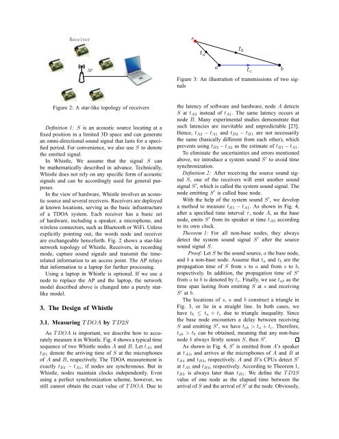
st aat bt cFigure 3: An illustration of transmissions of two signalsbFigure 2: A star-like topology of receiversDefinition 1: S is an acoustic source locating at afixed position in a limited 3D space and can generatean omni-directional sound signal that lasts <strong>for</strong> a specifiedperiod. For convenience, we also use S to denotethe emitted signal.In <strong>Whistle</strong>, We assume that the signal S canbe mathematically described in advance. Technically,<strong>Whistle</strong> does not rely on any specific <strong>for</strong>m of acousticsignals and can be accordingly used <strong>for</strong> general purposes.In the view of hardware, <strong>Whistle</strong> involves an acousticsource and several receivers. Receivers are deployedat known locations, serving as the basic infrastructureof a <strong>TDOA</strong> system. Each receiver has a basic setof hardware, including a speaker, a microphone, andwireless connectors, such as Bluetooth or WiFi. Unlessexplicitly pointing out, the words node and receiverare exchangeable hence<strong>for</strong>th. Fig. 2 shows a star-likenetwork topology of <strong>Whistle</strong>. Receivers, in recordingmode, capture sound signals and transmit the timerelatedin<strong>for</strong>mation to an access point. The AP relaysthat in<strong>for</strong>mation to a laptop <strong>for</strong> further processing.Using a laptop in <strong>Whistle</strong> is optional. If we use anode to replace the AP and the laptop, the networkmodel described above is changed into a purely starlikemodel.3. The Design of <strong>Whistle</strong>3.1. Measuring <strong>TDOA</strong> by TD2SAs <strong>TDOA</strong> is important, we describe how to accuratelymeasure it in <strong>Whistle</strong>. Fig. 4 shows a typical timesequence of two <strong>Whistle</strong> nodes A and B. Let t A1 andt B1 denote the arriving time of S at the microphonesof A and B, respectively. The <strong>TDOA</strong> measurement isexactly t B1 − t A1 , if nodes are synchronous. But in<strong>Whistle</strong>, nodes maintain clocks independently. Evenusing a perfect synchronization scheme, however, westill cannot obtain the exact value of <strong>TDOA</strong>. Due tothe latency of software and hardware, node A detectsS at t A2 instead of t A1 . The same latency occurs atnode B. Many experimental studies demonstrate thatsuch latencies are inevitable and unpredictable [23].Hence, t A2 − t A1 and t B2 − t B1 are not necessarilythe same (basically different from each other), whichprevents using t B2 −t A2 as the estimate of t B1 −t A1 .To eliminate the uncertainties and errors mentionedabove, we introduce a system sound S ′ to avoid timesynchronization.Definition 2: After receiving the source sound signalS, one of the receivers will emit another soundsignal S ′ , which is called the system sound signal. Thenode emitting S ′ is called base node.With the help of the system sound S ′ , we developa method to measure t B1 −t A1 . As shown in Fig. 4,after a specified time interval τ, node A, as the basenode, emits S ′ from its speaker at time t A3 accordingto its own clock.Theorem 1: For all non-base nodes, they alwaysdetect the system sound signal S ′ after the sourcesound signal S.Proof: LetS be the sound source,athe base node,and b a non-base node. Assume that t a and t b are thepropagation time of S from s to a and from s to b,respectively. In addition, the propagation time of S ′from a to b is denoted by t c . Finally, we use t ab as thetime span lasting from emitting S at s and receivingS ′ at b.The locations of s, a and b construct a triangle inFig. 3, or lie in a straight line. In both cases, wehave t b ≤ t a + t c due to triangle inequality. Sincethe base node encounters a delay between receivingS and emitting S ′ , we have t ab > t a +t c . There<strong>for</strong>e,t ab > t b can be obtained, meaning that any non-basenode b always firstly senses S, then S ′ .As shown in Fig. 4, S ′ is emitted from A’s speakerat t A3 , and arrives at the microphones of A and B att A4 and t B3 , respectively. A and B’s CPUs detect S ′at t A5 and t B4 , respectively. According to Theorem 1,t B3 is always later than t B1 . We define the TD2Svalue of one node as the elapsed time between thearrival ofS and the arrival ofS ′ at the node. Obviously,