FSL-25 Install - Waltco
FSL-25 Install - Waltco
FSL-25 Install - Waltco

You also want an ePaper? Increase the reach of your titles
YUMPU automatically turns print PDFs into web optimized ePapers that Google loves.
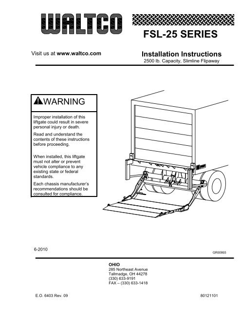
<strong>FSL</strong>-<strong>25</strong> SERIESVisit us at www.waltco.com<strong>Install</strong>ation Instructions<strong>25</strong>00 lb. Capacity, Slimline FlipawayWARNINGImproper installation of thisliftgate could result in severepersonal injury or death.Read and understand thecontents of these instructionsbefore proceeding.When installed, this liftgatemust not alter or preventvehicle compliance to anyexisting state or federalstandards.Each chassis manufacturer’srecommendations should beconsulted for compliance.6-2010GR00993OHIO285 Northeast AvenueTallmadge, OH 44278(330) 633-9191FAX – (330) 633-1418E.O. 6403 Rev. 09 80121101
Table of ContentsChapterINTRODUCTION ......................................................................................................................................................SAFETY INFORMATION ....................................................................................................................................... 1LIFTGATE TERMINOLOGY ................................................................................................................................... 2BASIC MOUNTING REQUIREMENTS .................................................................................................................. 3INSTALLATION ...................................................................................................................................................... 4PLACEMENT OF DECALS .................................................................................................................................... 5LUBRICATION INSTRUCTIONS ........................................................................................................................... 6FINAL INSPECTION .............................................................................................................................................. 7HOW TO ORDER PARTS ...................................................................................................................................... 8OPTIONAL KIT INSTRUCTIONSHAND HELD REMOTE KIT ...................................................................................................................... 80101485KIT #80000430AUX BATTERY KIT (TRUCK) .................................................................................................................. 80101387KIT #80001066AUX BATTERY KIT (TRAILER) ............................................................................................................... 80101387KIT #80001069TRACTOR WIRING KIT ........................................................................................................................... 80100822KIT #80000618ANTI THEFT KIT ...................................................................................................................................... 80101227KIT #80000812CAB SHUTOFF KIT .................................................................................................................................. 80101363KIT #80000827REMOTE PUMP MOUNT KIT .................................................................................................................. 80101284KIT #80000979COPPERHEAD SNAKE KIT ..................................................................................................................... 80101426KIT #80001087E.O. 6403 Rev. 09 80121101
INTRODUCTIONIf anyone observes improper installation, improper operation, or damage, they should immediatelycontact a qualified person for assistance and correction. We strongly urge anyone that has anyquestions or doubts as to the installation, condition, use, operation, maintenance or repair of the liftgateto contact us at <strong>Waltco</strong> where we have qualified personnel that will be happy to assist you. Telephonenumbers and addresses of these locations are listed in the Owner’s Manual and <strong>Install</strong>ationInstructions.INSTALLATION<strong>Waltco</strong> liftgates should only be installed by those with sufficient basic skills to understand theinstallation and operation of the liftgate, along with the equipment on which the liftgate is beinginstalled. <strong>Waltco</strong>’s installation instructions are not intended to give rationale for all the instructions thatare given; however, it is the intent of these instructions to give the installer both the operations andwhat we believe to be the most desirable sequence of implementing these operations. Theseinstructions can in no way expand into an area where they will replace a qualified person, or clearthinking and a basic knowledge that must be possessed by the installer.It has been our experience that a knowledgeable journeyman following these instructions andobserving the operation of the liftgate will have a sufficient comprehension of the liftgate to enable thisperson to troubleshoot and correct all normal problems that may be encountered.Failure to follow the installation instructions, adjustments and mounting dimensions may result inimproper and unsafe operation of the liftgate. Unauthorized alterations of the liftgate can cause anundesirable and dangerous condition.OWNER’S MANUALThe <strong>Waltco</strong> Owner’s Manual is intended to act as a guide for operation and routine maintenance butis no way intended to encourage usage or repair of the liftgate by those who are not qualified to do so.The contents of the owner’s manual include, but are not limited to general operation instructions,routine lubrication, parts lists, and an outline of things that should be checked but may not be obviousto those not technically qualified. This manual assumes the liftgate is properly installed, undamagedand operates correctly. Improper installation, improper operation, or damage should be immediatelycorrected by a qualified person.INSPECTIONAs part of the regular inspection of a liftgate and after damage or suspicion of an overload, inspectfor wear or structural damage and make necessary repairs or replacements. Check all structuralcomponents and their attachment to the liftgate for cracked welds, loose fasteners, wear and partdeformation. Check cylinder and hose for leaks. Inspections and repairs should be made by a qualifiedmechanic.REPLACEMENT PARTSUse only <strong>Waltco</strong> original equipment replacement parts. Components of other liftgate manufacturersmay outwardly appear to be the same but are not interchangeable with <strong>Waltco</strong> products. <strong>Waltco</strong>components are specifically designed for safety requirements, reliability and compatibility with ourproducts. Refer to your <strong>Waltco</strong> parts manual when ordering parts. NOTE: When ordering, give modeland serial number of liftgate.DECALSIt is important that every vehicle that has a WALTCO Liftgate have legible DECALS clearly posted onthe vehicle and an OWNER’S MANUAL in the vehicle at all times as a guide for proper operation andmaintenance.Additional DECALS and OWNER’S MANUALS can be obtained from WALTCO TRUCKEQUIPMENT COMPANY 80101388 Rev 02 EO 6156
Chapter 1Safety InformationWARNINGRead, understand, and follow all of the warning listed below.Failure to follow these warning could result in severe personal injury or death.Read and understand the Owner’s Manual, all decals and warning on liftgate before operating liftgate.Do not operate liftgate without a thorough knowledge and understanding of the operation of the liftgate.Liftgate hazards can result in crushing or falling.This liftgate is designed for loading and unloading of cargo. If personnel are required to ride liftgate, observeand familiarize yourself with the liftgate operation, decals and manuals. Ensure stable footing at all times.Do not ride liftgate with unstable loads.Wheeled loads must be properly retained from rolling.Tall, high center of gravity loads must be retained from falling over.Never overload liftgate.Refer to the Explanation of Specification Tag in the Liftgate Terminology chapter for liftgate capacity rating.Keep hands and feet clear of all potential pinch points.Never use liftgate if it makes any unusual noise, has unusual vibration, raises or lowers unevenly, or fails tooperate smoothly.Never use liftgate if it shows any signs of structural damage such as cracked welds, bent or distortedmembers.Do not attempt any repairs unless you are qualified to do so. Care should be taken when work is performedon a disabled liftgate located near moving traffic. When possible the vehicle should be moved away fromtraffic areas for repair. Precautionary measures should be taken to ensure personal safety including thoserecommended in Federal Motor Vehicle Safety Standards 571.1<strong>25</strong>.All protective covers, guards, and safety devices must be in place and access doors closed before operatingliftgate.Do not allow anyone to stand in, or near area, in which Platform will open and close before opening or closingPlatform.Do not allow anyone to stand near the Platform where a falling load could land on them.Platform is always to be properly stored and secured for transit. See the Owner’s Manual for details.Take care to retain cargo during transit for liftgate Platforms which function as the tailgate or door of the cargoarea. Small objects can fall through the space between the vehicle and the folded Platform.A Lock-Out device or Shut-Off Switch should always be used to prevent unauthorized use of liftgate.For liftgates with Runners, never use liftgate if Runners do not travel freely and smoothly.For liftgates with Roller Lifting Chain, the Chain should be replaced every (5) five years or 15,000 cycles,whichever comes first. Replace only with <strong>Waltco</strong> approved Roller Chain.Never transfer loads which exceed lifting capacity on or over any part of the Platform unless the liftgate isequipped with a special reinforced Platform and Platform Support Bars for use when the Platform is used asloading ramp (dock board). Refer to the “Using Platform as a loading ramp” Chapter in the OperationInstructions of the BZ/RZ series Owner’s Manual.For liftgates equipped with Trailer Hitches, never exceed the rated capacity of the hitch. Do not exceed thevehicle’s weight rating. Refer to the vehicle’s Owner’s Manual.Vehicle must comply with all state and federal standards.Follow the “Maintenance Guide” chapter in the Owner’s Manual.Page 1 - 180101<strong>25</strong>3 Rev 03 EO 6156
Chapter 1Safety InformationLiftgates with Tilt FunctionProper use of the Control Switches is of extreme importance.Improper use of Tilt Switch could cause load to fall from the Platform or damage the liftgate.Platform should be in a generally horizontal position when raising or lowering with a load.In any tilt position, the Platform may vary from level while raising or lowering the Platform.Liftgates equipped with spring operated Cam CloserReplace Cam Release Spring every five (5) years or 15,000 cycles, whichever comes first.RGL-Series LiftgatesMake certain Platform Brake mechanisms are operating properly.The Runners are always to remain powered up against the Upstops Pins when in transit.Inspect Cables every three (3) months or 750 cycles, whichever comes first. Cables must be replaced if theyshow signs of wear, distortion, kinking or if any broken wires are visibleReplace cables every five (5) years or 10,000 cycles, whichever comes first.This is the safety alert symbol. This manual uses this symbol to alert you to potential personal injuryhazards.Obey all safety messages that follow this symbol to avoid personal injury or death.SIGNAL WORDSWARNINGIndicates a potentially hazardous situation, which if notavoided, could result in death or serious injury.Black letters on an orange backgroundCAUTIONIndicates a potentially hazardous situation, which if notavoided, may result in minor or moderate injury. Mayalso be used to alert against unsafe practices.Black letters on a yellow background.NOTICEIndicates a potentially hazardous situation, which if notavoided, may result in property damage.WARNINGCAUTIONNOTICEPage 1 - 280101<strong>25</strong>3 Rev 03 EO 6156
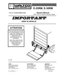
Chapter 2Liftgate Terminology1. Hydraulic Cylinder2. Barbed Fitting3. Return Line4. Hydraulic Fitting (Eldbow)5. Pressure Compensated Flow Valve6. Hydraulic Fitting (Connector)7. Pump Reservoir8. Steel Plug9. Hydraulic Hose10. Breather11. Drain Plug12. Start Solenoid13. Motor14. Lowering Solenoid15.16.GravityDownPower Down(optional)GR00995Page 2-1
Chapter 2Liftgate Terminology17. Latch Chain18. Bed Extension19. Dock Bumper Brace20. Dock Bumper21. Pump Cover22. Stop Block Adjustment Bolt23. Mount Tube Assembly24. Mount Plate<strong>25</strong>. Parallel Arm26. Lift Arm Assembly27. Deck Assembly28. Deck Extension Assembly29. Specification Tag30. Stop BlockGR00996Page 2-2
Chapter 2Liftgate TerminologyExplanation of Specification TagModel Description Capacity<strong>FSL</strong>-<strong>25</strong> Slimline Flipaway <strong>25</strong>00 lbs.MODELRATED CAPACITYBased on an evenlydistributed load on theplatform flat surface.SERIAL NUMBERof liftgate. To be usedwhen ordering parts orwhen contacting <strong>Waltco</strong>for service or warrantyquestionsDATE OFMANUFACTUREMonth / YearGR00241SpecificationTagGR00996Page 2-3
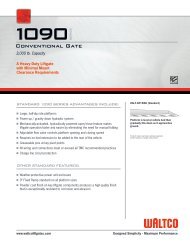
Chapter 3Basic Mounting RequirementsMeasure distance from ground to floor level. This isthe bed height.Refer to bed height dimension on mounting chartto determine basic mounting dimension “A” andminimum mount frame clearance required.NOTE:Max bed height dimensions for unloaded vehicle.Min bed height dimensions for fully loaded vehicleNOTE:Tire clearance should be 6” minimum between tireand mount frame.Bed Height(Ground to Floor)GR00139Bed Height<strong>FSL</strong>-<strong>25</strong> ONLYMOUNTING CHARTMount Frame“A” DimensionClearanceGroundClearance53”- 54” 22-3/4” 35-1/4” 22-1/4” – 23-1/4”51”- 52” 22” 36” 21” – 22”49”- 50” 21” 37” 20” – 21”46”- 48” 20” 38” 18” – 20”43”- 45” 19” 39” 16” - 18”36”- 42” (Loaded)Maximum Platform depth 26”for this bed height range18-1/2” 39-1/2” 9-1/2” – 15-1/2”30-7/8”12”18-1/2”3-3/8” 15-3/4”“A”Dimension8”8-5/8”6” MinimumClearance12-1/2”Mount FrameClearance (ref.)40-5/8” 40-5/8”GR01078Page 3-1
Chapter 4Liftgate <strong>Install</strong>ationPREPARATION OF BODY SILLRemove all obstructions that would interfere withoperation of Liftgate; such as dock bumpers, trailerhitches, projections, etc.Locate and mark the center of body sill.NOTE:All mounting measurements for centering liftgatewill come from centerline mark.6” MaxCenterline ofFloor and Sill3-3/4”MaxBody sill must have clearances indicated. Cut or notchRear Sill to obtain these clearances.Refer to chart page 3-1Rear Sill64”45˚ Typ9-1/2”TypGR00624Cut away chassis frame to obtain clearances indicated.6”14”17”GR00143Cap Vehicle Frame, using a 3/16” or 1/4” X 2” steelstrap.Body CrossmemberVehicle Frame3/16” or 1/4” X2” Steel StrapGR006<strong>25</strong>Page 4-1
Chapter 4Liftgate <strong>Install</strong>ationINSTALLATION OF BED EXTENSIONLocate and mark centerline of Bed ExtensionNOTE:All mounting measurements for centering liftgatewill come from Bed Extension centerlineClamp two pieces of channel or bar stock to BedExtension.Lift Bed Extension up and place channels onbody floor, hanging Bed Extension on body.NOTE:Be sure that Floor and Bed Extension centerlinesare in line.NOTE:When irregular Sill exists, cut or shim Gussets tomake Bed Extension level with vehicle floor.Centerline ofBed ExtensionCenterlineof FloorCut orShimGR00626Weld Bed Extension in place to Sill.Place a 1/8” x 1” weldabove each Gussetas shown1/8” x 2” weldstypical bothsides ofGussetsPlace a 1/8” x 2” weldat the bottom of eachGussetGR00627Page 4-2
Chapter 4Liftgate <strong>Install</strong>ationPREPARATION OF MOUNT FRAMERemove Parallel Arms from liftgate.Keep Shipping Pins and Retaining Bolts and Nuts.These will be used later, and at final assembly.NOTE:Do not remove shipping band that binds Lift ArmAssembly to Mount Tube.Parallel ArmPin and RetainingBolt & NutShippingBandGR02730INSTALLATION OF HANGER BRACKETSBolt Hanger Brackets To Bed Extension.Check that 7-1/8” dimension from Sill to center of holein Bracket is held.BoltEnsure that Hanger Brackets are securelyfastened to Bed ExtensionNut7-1/8”1-3/8”HangerBracketGR00629HANGING MOUNT FRAMEPosition Mount Frame and Lift Arm Assembly(still banded together) under Bed Extension.Raise Mount Frame and align holes in Lift Arms andHanger Brackets.Using Shipping Pins, Bolts and Nuts provided, attach LiftArms to Hanger Brackets.Be sure to reinsert Bolts and Nuts toensure that Lift Arms do not fall or slideoff.Lift ArmNutShipping PinBoltHangerBracketGR00630Page 4-3
Chapter 4Liftgate <strong>Install</strong>ationPOSITIONING MOUNT FRAMEPlace hydraulic floor jack under Mount Tube with handlepointing to front of truck. Raise until Mount Tube restssecurely on jack.Cut and remove shipping band between Lift ArmAssembly and Mount Tube.Raise jack until top of Mount Tube is at desired “A”dimension. (Refer to Basic Mounting Requirements,page 3-1)Rotate Mount Tube until pump bracket is level withground.NOTE:Proper rotation of Mount Tube can be verified bysubtracting “Y” dimension from “X” dimension, thisshould be 6-5/16”.Pump Bracket to be levelX“A”DimensionOther means may be used to supportMount Frame in position. ALWAYS verifythe safety of your supporting methodbefore proceeding.YIf properly installed, X – Y = 6-5/6”GR00631MOUNT PLATE INSTALLATIONLocate mount plates on mount tube. Mount platesshould be approximately 90° to vehicle frame.Check that mount plates extend a minimum of 5-1/4"above bottom of vehicle frame. If dimension cannot beheld, refer to the optional installation.1/4” weld 100%, threesides of mount platesas shown.Shield all wires and hoses from heat andweld splatter.Recheck “A” dimension. Weld three sides of mountplates 100% to vehicle frame with 1/4” weld.Weld mount tube to the mount plates. Weld all around,both sides of the mount plates, and ends, with 1/4" weld.5-1/4”Min.MountPlateMountTube1/4” weld 100%, allaround both sides andends of mount plates.Page 4-4GR00472
Chapter 4Liftgate <strong>Install</strong>ationOPTIONAL INSTALLATIONIf the 5-1/4” dimension cannot be met a 3/8” thickplate must be added.Recheck “A” dimension. Weld three sides of mountplates and three sides of 3/8” plate 100% with 1/4” weld.Weld mount tube to mount plates. Weld all around, bothsides of mount plates, and ends, with 1/4" weld.Shield all wires and hoses from heat andweld splatter.1/4” weld 100%, threesides of mount plates andadapter plates as shown.5-1/4”Min.5-1/4”Min.3/8”adapter plate1/4” weld 100%, allaround both sides andends of mount plates.GR00473NOTE:If necessary, liftgate may be mounted to inside offrame.One 8” to 12” channel or two5” to 6” channelsTruck Frame5-1/4” Min.Weld channelto Truck Framewith 1/4“ weld.Weld 100% allaround asshown.37” or widerWeld Mount Plate tochannel with 1/4” weldafter channel is weldedto the Truck Frame.GR01713BRACING THE CYLINDER TOWERForm a 1/4” x 2” steel strap to reach from top of CylinderTower to a Frame Cross Member.Attach at both ends with a minimum 3/16 x 2” weld.weldSteel StrapweldShield all wires and hoses from heat andweld splatter.Page 4-5TruckFrameCrossmemberCylinderTowerGR00163
Chapter 4Liftgate <strong>Install</strong>ationINSTALLATION OF CONTROLSLocate Switch such that, when operating liftgate,operator will have clear view of entire platform areaand will not be in area that liftgate will pass through.<strong>Install</strong> Switch Mounting Template Decal (or use thisdiagram). Locate screw holes. Drill four (4) holes witha #26 (0.147"dia.) drill bit.1.752.80”Hole forControl Cord(optional)NOT ACTUAL SIZE0.147”Dia. HoleGR02181If Control Cord will be run through a hole in side of body,remove all sharp edges from hole and insert a grommet.Use #8 Self-tapping Screws to secure switch.#8 Self-TappingScrewsMOUNTING PUMP UNIT<strong>Install</strong> pump mount plate gasket (peel off backing andstick to plate).<strong>Install</strong> grommets into pump mount plate.Attach pump to pump mount plate with bolts andwashers provided.<strong>Install</strong> hydraulic lines to pump at back of pump mountplate.Route Hydraulic hoses to the liftgate Cylinder Tower.Do not connect the hoses to cylinders at this time.Pump MountPlateMount Plate GasketHydraulic LinesMounting HardwareGrommetsGR01999GR01111PUMP WIRINGRoute Control Cord from Switch to Pump Plate.<strong>Install</strong> grommets (supplied) as shown on Control Cordand Battery Cable. Secure cables to vehicle with cableties provided.Connect Control Cord and Battery Cable to pump asshown. Connectors are gendered to allow only correctconnections.GREENPOWERPage 4-6WHITERAISEBLACKLOWERGR02000
Chapter 4Liftgate <strong>Install</strong>ationINSTALLATION OF POWER CABLELocate and mount 150 Amp circuit breaker directly tobatteries using copper terminal link supplied.Circuit breaker must be mounted to give good protectionagainst any objects coming into contact with circuitbreaker terminals and causing a short. Position mustalso be readily accessible to reset breaker.NOTICE:Circuit Breaker is to rest solidly on batteryto prevent vibration during transit.If unable to connect circuit breaker direct to batteries,an optional 24”, maximum length, 2 Ga. battery cablemay be used.Connect end of battery cable from liftgate to TerminalLink attached to circuit breaker.Apply a generous amount of Dielectric Grease to allBattery terminals and Circuit Breaker terminals.Secure all battery cables to chassis frame with cableties provided.NOTICE:Original equipment ground cable furnished onvehicle should be at least a number 2 ga. to insureproper operation of pump unit. An auxiliary groundcable should be added between engine block andchassis frame if engine is not adequately groundedto chassis frame. When there are two or morebatteries, all cables connecting batteries togethermust be 2 ga. or heavier. This includes all originalequipment batteries on vehicle.150 Amp Circuit BreakerBattery CableFrom LiftgateCopper Terminal LinkProtect wires from any sharp edges orholes that may abrade insulated coveringof wires.Secure battery cable so it does not comenear, or in contact with, other vehiclewiring, fuel lines, brake lines, air hoses,exhaust system, etc.GR00080Page 4-7
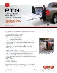
Chapter 4Liftgate <strong>Install</strong>ationDIVERT WATER FROM ENCLOSURETo help prevent channeling water into pump or batteryenclosures:Secure hoses, cables and cords downward asthey exit the enclosure.If a downward exit is impractical, a Zip Tie canbe installed around hose or cable to helpinterrupt the flow of water as shown.Zip TieFlow of waterPump or BatteryEnclosureGR02460Basic gravity down liftgate wiringGR01994Hydraulic Schematic – Gravity DownHydraulic CylinderLowering Speed FlowControl Valve (pressurecompensative, nonadjustable)Pump/ReservoirLoweringSolenoidValveGR0<strong>25</strong>95Page 4-8
Chapter 4Liftgate <strong>Install</strong>ationBasic power down liftgate wiringPM-618CHydraulic Schematic – Power DownLowering Speed FlowControl Valve (pressurecompensated)Hydraulic CylinderLowering SolenoidValvePump/ReservoirRaiseSolenoidValveGR0<strong>25</strong>96Page 4-9
Chapter 4Liftgate <strong>Install</strong>ationHYDRAULIC CYLINDER INSTALLATIONExtend Cylinder Shaft to remove air.<strong>Install</strong> Pressure Compensated Flow Control Valve andall hoses and fittings as shown.Pressure Compensated Flow Control Valvemust be installed as shown, with arrow onvalve pointed away from cylinder.ConnectorReturn LineBarbed FittingHydraulic LinePressureCompensatedFlow Valve90º ElbowGR02731CONNECTING UPPER CYLINDER HOSE (POWERDOWN LIFTGATES)Connect elbow to adapter as shown.NOTE:Do not use sealer.GR01039HOSE INSTALLATIONAvoid twisting of hoses.Avoid sharp bends when routing hosesHoses will contract under pressure. Allow plenty ofslack between connecting points.Do not clamp hoses at bends to allow for lengthchanges when hose is pressurized.High PressureNo PressureGR00717FILLING HYDRAULIC RESERVOIRPosition liftgate deck per chart below (use forklift,crane, or other safe device).Remove Reservoir Plug.Oil level should be 1/2” from top of reservoir.If low, fill as required. Use appropriate fluid per chart.Replace Plug.Run liftgate full cycle several times to release trappedair from system.PlugGR02130Page 4-10
Chapter 4Liftgate <strong>Install</strong>ationLIFTGATE POSITION FOR OIL LEVEL CHECKGravity Down Pump:Power Down Pump:Deck should be in this position:Ground LevelBed LevelRecommended FluidsTemperature RangeAcceptable Fluids-10 to 195 F Mobil DTE 13MShell Tellus 32T-<strong>25</strong> to 140 F Mobil DTE 11MShell Tellus 15T-40 to 145 F Mobil Aero HFAExxon Univis HVI 13-45 to 200 F Exxon Univis HVI 26A good quality SAE 10W motor oil may also be usedin temperatures above 32 F.Fill reservoirFill with recommended fluid or equivalent.Fill the reservoir to within 1/2” from the top.NOTICE:Do not use the following fluids:Brake FluidPower steering fluidAutomatic Transmission Fluid (ATF)CYLINDER INSTALLATION<strong>Install</strong> Cylinder first by placing in Cylinder Tower.NOTE:Apply a generous amount of automotive typechassis grease before installing Cylinder PinsEnsure cylinder port faces towards front of vehicle.Connect Cylinder Shaft to Lift Arms by retracting withhydraulic pressure until hole in shaft aligns with holes inLift Arm clevises.Insert Lower Cylinder Pin and retain with Grade 8 Boltand Coiled Pin.NOTE:Take care not to nick or scratch Cylinder ShaftUpper CylinderPinCoiled PinGrade 8 BoltLower CylinderPinGR00637Page 4-11
Chapter 4Liftgate <strong>Install</strong>ationPLATFORM INSTALLATIONRemove pins from lift arms and brackets.NOTE:Keep pins, bolts, and nuts, they will be used later.Lower Lift Arms to ground position.Remove Hanger Brackets from Bed Extension.Position Platform Assembly directly below BedExtension.Raise or lower Lift Arms until holes line up with insidelower holes in Platform Assembly Hinge.<strong>Install</strong> Long Deck Pins and Washers EXACTLY asshown, and retain with Coiled Pins.NOTE:Long Deck Pin is not to extend past surfaceindicated.Use one or two washers as required.LongDeck PinPlatformLift ArmCoiled PinLong Deck Pin isnot to extend pastthis surfaceWashers (1 or 2)GR00638PARALLEL ARM INSTALLATIONRemove shipping band from Platform.Fold Platform between Lift Arms.Using raise switch, raise Platform up until heel ofPlatform is within one inch of Bed Extension.Hold upper ends of Parallel Arms in Stop Blocks andinstall Hinge Pins and Coiled Pins.NOTE:Unscrew Jam Nut on Eye Bolt to facilitateattachment of arm to Platform. Retighten afterarm is attached.Jam Nut / Eye BoltParallel ArmSpringGR00639Align holes in both Parallel Arm and Platform Shoe andinstall Pins, bolts, and nuts (used to earlier to hangliftgate).Note:Use the hole in the pin closest to the head of thepin.GR00640Page 4-12
Chapter 4Liftgate <strong>Install</strong>ationEQUALIZER BAR INSTALLATION<strong>Install</strong> Equalizer Bars, 1/2” Washers and Cotter Pins.Attach Springs to Equalizer Bars. Attach opposite endsto Clips on each Stop Block with “S” Hooks provided.Crimp ends of “S” Hooks and weld.Cotter Pin½” Washer1/8” Tack Weld all“S” HooksSpringEqualizerBar“S” HookSpring Clip“S” HookGR00641STOP BLOCK ADJUSTMENTTurn both 3/4” hex nuts at Stop Blocks until DeckExtension tip is at least 3/4” above Bed Extension.Adjust both sides evenly.Adjustment Nut¾”Min.Stop BlockGR00164Weld a steel triangle bar as a Leveling Set to eachstop block.NOTE:Weld leveling set to Stop Block ONLY.DO NOT weld to outer Clevis or Pivot Pin.Tighten both nuts securely.Weld fully, twosides, to StopBlock. 3/16” weld.StopBlockLeveling SetGR00165Page 4-13
Chapter 4Liftgate <strong>Install</strong>ationDECK EXTENSION UPSTOP INSTALLATIONPut Liftgate in stored positionMake sure that Deck Assembly is tight againstunderside of Bed ExtensionPull Deck Extension tight, up and away from vehicle(as indicated by arrow).Ensure Deck Extension rests on top of Lift Arm Pin(see point “X”).Locate Upstops on Deck Hinge and weld.IMPORTANT:Be sure Upstops are against Deck Extension SidePlates. Weld to Deck Assembly ONLY.Unfold and fold Deck Assembly to make certain DeckExtension fits snugly between Lift Arm Pin and Upstopson Deck AssemblyPlatformUpstopBed ExtensionLift ArmAssemblyXDeckAssemblyWeld Upstopswith 3/16” weldtwo sides 100%as shownDeckExtensionDeck HingeGR00642ADJUSTING PLATFORM FOLDING EFFORTAdjusting tension of parallel arm springs may improvefolding/unfolding of the platform for some installations.Adjust springs on both arms equally.Tighten nuts securely.Upper SpringIf spring assist is too strong, platform mayunfold without assistance when loweringto ground. This is unsafe and MUST BECORRECTED.Reduce parallel arm spring tenstion.When adjustment alone does not eliminatethe problem, remove lower spring fromone or both parallel arms. Adjustremaining springs for best operation.NOTE:To prevent damage to Parallel Arms, upper springmust always have more tension than lower spring.Lower SpringAdjustment NutsGR00167Page 4-14
Chapter 4Liftgate <strong>Install</strong>ationINSTALL RUBBER SNUBBERSRaise Platform to fully closed position. Pull up andrearward on Deck Extension to make certain Platformis fully in stored position.Measure distance “X” from tube at end of deck to aselected spot on chassis frame.Lower platform slowly until “X” increases by 3/8”.“X”GR00168Position a Snubber Assembly approximately as shownon each Mount Plate and tack weld in place.Lower, open and re-store Platform a few times to checkoperation of Snubbers.Check that Snubber Assemblies do not interfere withopening or storing away of deck.Weld Snubbers 100% with 1/4” welds.Mount PlateSnubber AssemblyPad to touch Platformend tube.Weld 100%, all aroundGR00169DOCK BUMPER INSTALLATIONLocate Dock Bumper Channel against Bed ExtensionSide Plate and weld with 3/16” weld 100%.Position Bumper Braces approximately as shown andweld with 3/16” weld 100%.BedExtensionSide PlateWeld DockBumper to BedExtension usinga 3/16” weldBumper BraceBed ExtensionDock BumperGR00643Page 4-15
Chapter 4Liftgate <strong>Install</strong>ationLATCH CHAIN INSTALLATIONRaise Platform to stored positionWeld Chain Clip to underside of curb side Parallel Armwith 3/16” weld all around.NOTE:The clip must be located below bend in Parallel Arm.Weld Latch Chain Assembly to Bed Extension 100%.Chain Clip to slant inward,toward PlatformChain ClipBed ExtensionLatch ChainAssemblyParallel ArmGR00644When Dock Bumpers are used, weld Latch ChainAssembly to inside of Bumper with a 3/16” weld allaround.Latch chain is an important safety item andmust always be installed. A pad lock canbe used in place of hook to preventunauthorized persons from operatingliftgate.Latch ChainAssemblyDockBumperThere is no speed adjustment on this liftgate.Lowering speed is controlled by the pressurecompensative valve plumbed at the cylinder.Regardless of weight on platform, liftgate should lowerat approximately six (6) inches per second.GR00645Bed Height (inches)6= Lowering Time (seconds)This liftgate must have the correctpressure compensative valve install:<strong>FSL</strong>-<strong>25</strong> = 70110020Pressure CompensativeFlow Control ValveGR0<strong>25</strong>97GR00160Page 4-16
Chapter 4Liftgate <strong>Install</strong>ation<strong>Waltco</strong> offers three suggestions for the installation of thevehicle taillights. We believe these suggested locationsmeet D.O.T. regulations but do not warrant that they do.Your installation of the vehicle taillights should meet allapplicable regulations and requirements. This is in noway to infer that these suggestions are the only correctmethod of installing taillights.Location “B”Location “A”Location “A”: Mount lights beneath the bed extensionskin, if there is sufficient room.Location “B”: Mount lights above bed extension or intothe body rear corner posts.Location “C”: <strong>Waltco</strong> has dock bumpers available thathave lights included as part of the dock bumper.NOTE:Original equipment lights may not provide sufficientclearance at this location so a narrower light may berequired.Location “C”All lights must be installed in accordancewith all applicable D.O.T. regulations.GR0<strong>25</strong>03Page 4-17
Chapter 5Placement of DecalsAll decals must be in place and legible or all warranties are void.ITEM DECAL QTY PART NO. LOCATION1Safety Instructions 1 80100850Operation 1 80100854Hazard Decal 1 80101370Important Decal 1 80100828Stand Clear Decal 1 75089296Motor Thermal Switch 1 80101480<strong>FSL</strong>-<strong>25</strong> - <strong>25</strong>00 lb 1 80100<strong>25</strong>5Locate in a conspicuous place near controls.If your liftgate is equipped with dual controls, anadditional Safety Instruction decal (80100850) isto be placed in a conspicuous place near thesecond set of the controls.Refer to the following diagram showing decal locations.Use Handle Decal 1 75089295 Locate near platform handle2Stand Clear Decal 1 75089296<strong>FSL</strong>-<strong>25</strong> - <strong>25</strong>00 lb 1 80100<strong>25</strong>5(positioned so as to be read when platformis being unfolded into loading position)3 Stand Clear Decal 1 75089296 Locate on driver’s side of vehicle body near liftgate4 Circuit Breaker Decal 1 80100829Locate next to liftgate circuit breaker.In applications where more than one circuit breakeris used, this decal must be placed in both locationsTo maximize decal adhesion to surfaces:Surface must be dry and cleanFirm pressure must be applied to decalMinimum surface temperature 65ºHeat gun may be used to heat surfaceGRGR0<strong>25</strong>04Page 5-1
Chapter 6Lubrication InstructionsThe liftgate should be lubricated every 120 days.#1 – Grease with automotive type chassis grease with platform resting on ground.#2 – Grease with automotive type chassis grease with platform in stored position.#3 – Grease parallel arm slide with heavy chassis grease.#4 – Oil with a light weight machine oil.#5 – These are bearings that do not require grease, however, bearings can be sprayed with a non-petroleumbased lubricant such as Zep-45 to retard corrosion of pins, reduce friction, and increase bearing life.GR0<strong>25</strong>05Page 6-1
Ch 7FINAL INSPECTION SHEETIMPORTANT:All of the following are to be checked and verifiedbefore installation is complete.A. Is grade 8 bolt installed through collarand lower cylinder pin and retainedwith self-locking nut?B. Are all roll pins securely in place?C. Does liftgate fold and unfold properly?D. Does the platform meet the vehicleproperly?E. Is the platform held tightly when storedaway?F. Is safety chain installed in proper locationand orientation?G. Do controls operate properly?H. Are stop block leveling sets located andwelded properly?I. Are adjustment nuts and bolts tight?P. Are all parts properly lubricated accordingto the lubrication instructions?Q. Is 150 amp circuit breaker installed atbattery?R. Do lights operate properly(Note: Lights must be installed inaccordance with all applicable stateand federal D.O.T. regulations)S. Is license plate properly installed?T. Are all decals properly in place andlegible according to the decalplacement drawings?U. Is pump cover installed and securelylatched?V. Is the owner’s manual in the vehicle?J. Are bed extension, mount frame, mountplates, tower brace, up-stops, dockbumpers, bumper braces, taillight guardsand taillights all finish welded?K. Are hydraulic hoses and fittings properlyconnected with no leaks?L. Is battery cable attached and clampedtight?M. Are all electrical connections coated withdielectric grease?N. Has hydraulic system been properly bledof all air?O. Is pump reservoir full of oil?Do not use liftgate if any of the above are notchecked and verified. If you have any questionsnot covered in this manual, contact your nearest<strong>Waltco</strong> distributor, or the nearest <strong>Waltco</strong>factory.Page 7-1
Hand Held Remote <strong>Install</strong>ationDRILL SOCKET HOLESUsing dimension shown, drill mountingholes in desired location for socket.1-1/4” DIA.7/32” DIA.GR00036INSTALL SOCKETAssemble socket as shown.<strong>Install</strong> wires according to colors:W = White (Raise)B or BK = Black (Lower)G = Green (Power)GR02241CONNECT WIRES TO PUMP UNITThis step is for most liftgates, see nextpage for LPF liftgate instructions.Route Control Cord into pump enclosure.First connect Pump wires to Dual ControlAdapter Harness as shown.Connect both Control Cords to other ends ofAdapter Harness as shown.CONTROLCORDADAPTORHARNESSCONTROLCORDSOCKETNote!Match wire connections male to female. Colorof wire may vary.GR0208280101485 Page 1 EO6134 Rev.02
Hand Held Remote <strong>Install</strong>ationLPF Liftgate InstructionsLoosen cover bolt and remove Access Coverfrom center of Mount Tube.Remove Plastic Plug in top of Mount Tubeand insert Strain Relief Fitting through thesame hole. Tighten plastic Mounting Nut.MOUNTINGNUTSTRAIN RELIEFPLUGGR00335Remove Strain Relief cap nut and slide capnut over Control Cord.Insert Control Cord into Mount Tube throughStrain Relief, pushing one wire connectorthrough at a time.GR00336Route Control Cords behind Battery Cable,keeping them close to back wall of MountTube and away from battery cable stud(Contact between any connectors and batterycable stud could result in a short circuit).BATTERYCABLECONTROLCORDSConnect both Control Cords to three wayDual Control Adapter Harness.NOTE:Match wire connections male to female.Color of wire may varyADAPTERHARNESSGR00337Pull unsupported lengths of Control Cord out ofMount Tube and thread Strain Relief cap nutson snuggly. Do not over-tighten cap nuts, asthis may damage the wires.CABLE TIESUsing 8” cable ties provided, secure ControlCords to Hose Fittings as shown.Secure Control Cords to vehicle with 16”cable ties.GR0033880101485 Page 2 EO6134 Rev.02
BATTERY KIT INSTALLATIONS 80101387DETERMINE BATTERY AND PUMP LOCATION, ANDCABLE ROUTINGDetermine where pump unit and battery box will belocated. Make certain hydraulic hoses supplied willreach pump.Your installation may use only one cable supplied withliftgate, or, it may also use a cable supplied with thetrailer kit.Truck with auxiliary batteries:Cable supplied with liftgate will be cut into two lengths toreach from pump to auxiliary batteries and to vehiclebatteries.PUMPAUXILIARYBATTERYVEHICLEBATTERYTrailer with auxiliary batteries:Use cable supplied with liftgate from pump to auxiliarybatteries.Use cable supplied with trailer kit from auxiliary batteriesto nose of trailer.Note: Auxiliary batteries on trailers are to bemounted “mid-ship” on the trailer.GR01389Page 1 of 5 EO5507 Rev 024/1/05
BATTERY KIT INSTALLATIONS 80101387BATTERY AND PUMP BOX INSTALLATIONLocate battery box and pump box in a suitable locationunder the vehicle body (refer to previous page.)BODYCROSSMEMBERSWeld hanger channels to body crossmembers.PUMP BOXHANGERCHANNELSBATTERY BOXHint:To save space, hanger channels can be cut down andboxes moved closer together as shown.<strong>Install</strong> batteries.GR01390INSTALLATION OF BATTERY CABLE<strong>Install</strong> battery cable supplied with liftgate to the pumpstarter solenoid.For trucks:Route cable to vehicle batteries, cut to desired length.Cable runs tovehicle batteries ornose of trailerCut cable to reach auxiliary batteries, and cut remainingpiece to reach from auxiliary batteries to vehiclebatteries.For trailers:Route cable to auxiliary batteries, cut to desired length.Use cable supplied with trailer kit and route fromauxiliary batteries to nose of trailer.IMPORTANT: Do not connect cables to any batteriesat this time.GR01391Page 2 of 5 EO5507 Rev 024/1/05
BATTERY KIT INSTALLATIONS 80101387INSTALLATION OF TERMINAL LUGStrip 7/8” to 1” of insulation from end of cable.Slide heat shrinkable tubing onto cable.Insert bare wire into compression nut until it seats.IMPORTANT: Be sure to use correct compressionnut, use 2 gauge nut for 2 gaugecable, use 0 gauge nut for 0 gaugecable.Note: Copper wire should be flush with, or slightlypast nutHeat shrinkable tubingbefore installationCompression Nut7/8” to 1”GR00299Grip nut with wrench and turn terminal until nut seatsGR00300Position heat shrinkable tubing over terminal and end ofcableBeads of SealantShrink tubing using electric heat gun or torch.Note: To reduce chance of damaging tube andcable, a heat gun is recommendedApply sufficient heat to produce thin bead of sealant allaround tube edgesHeat ShrinkableTubingGR00301INSTALL OF TRAILER SOCKETRubber BootDrill 1-3/4” hole in nose of trailer for trailer socket.Strip 3/4” to 7/8” of insulation from end of cable.Slip rubber boot (supplied with socket) over cable.Solder cable into socket.After solder cools slip boot onto socket.Mount socket to trailer.Trailer SocketGR01392Page 3 of 5 EO5507 Rev 024/1/05
BATTERY KIT INSTALLATIONS 80101387Ground trailer socket to main structure of trailer.Use the 18” ground cable, supplied, and bolt it to thetrailer socket and suitable structure on the nose of thetrailer.An angle has been provided, it can be used by welding itto the crash plate, or other suitable structure.AngleTrailer SocketGround CableGR01414Page 4 of 5 EO5507 Rev 024/1/05
BATTERY KIT INSTALLATIONS 80101387INSTALLATION OF CIRCUIT BREAKER(S)Auxiliary batteries on a truck will require circuit breakersat both the auxiliary batteries and the vehicle batteries.Locate and mount 150 Amp circuit breaker directly tobatteries using copper terminal link supplied.Circuit breaker must be mounted to give good protectionagainst any objects coming into contact with circuitbreaker terminals and causing a short. Position mustalso be readily accessible to reset breaker.Note: Circuit Breaker is to rest solidly on battery toprevent vibration during transit.If unable to connect circuit breaker direct to batteries, anoptional 24”, maximum length, 2 Ga. battery cable maybe used.Connect end of battery cable from liftgate to TerminalLink attached to circuit breaker.Apply a generous amount of Dielectric Grease to allPositive (Hot) Battery terminals and Circuit Breakerterminals.Secure all battery cables to chassis frame with cable tiesprovided.IMPORTANT: Original equipment ground cablefurnished on vehicle should be at least a number 2ga. to insure proper operation of pump unit. Anauxiliary ground cable should be added betweenengine block and chassis frame if engine is notadequately grounded to chassis frame. When thereare two or more batteries, all cables connectingbatteries together must be 2 ga. or heavier. Thisincludes all original equipment batteries on vehicle.Important: Be certain wires are protected from anysharp edges or holes that may abrade insulatedcovering of wires.Cable suppliedwith LiftgateGroundCableCable from LiftgateTerminal LinksSee belowFor detailCable supplied withLiftgate or with TrailerKitImportant: Never secure battery cable in such a waythat it comes near, or in contact with, other vehiclewiring, fuel lines, brake lines, air hoses, exhaustsystem, etc.150 AmpCircuit BreakerCable to Vehicle Batteriesor to Nose of TrailerGR01413Page 5 of 5 EO5507 Rev 024/1/05
For Kit 80000812Anti-Theft KitANTI-THEFT KIT F, C, E PREINSTALLED PUMP SERIESINSTALLATION INSTRUCTIONSSlide 10021803 Anti-theft bar with cross bar over pump motor asshown.Locate 10021803 Anti-theft bar such that it contacts PumpMounting Plate in area that no Foam Gasket exists and its crossbar is over the Pump Motor. Make sure cross bar does notcontact, or come near, starter switch assembly. Weld asindicated.Locate 10021802 angles provided by centering each one overbolt heads on back side of Pump Mounting Plate and weld asindicated.IMPORTANTBe careful not to damage PlasticSolenoid when welding Anti-theft bar toPump Mounting Plate.GR100218021/8” weld X 1”. Eachleg of Angle to PumpMounting PlatePump MountingPlatePlasticSolenoidStarter SwitchAssembly1/8” weld 60% toPump MountingPlate. Typ.Foam GasketCross Bar10021803GR0220280101227 Page 1 of 1 E.O. 6098 Rev. 04
<strong>Install</strong>ation of Cab Shut Off Switch<strong>Install</strong> cab shut off switch and shut off switchdecal in convenient location in vehicle cab.DecalCab ShutOff SwitchGR00379Remove fuse line from motor solenoid.Unplug fuse line (or cut if required) fromswitch and save for later installation.Connect green 16 ga. cab shut off wireto switch.<strong>Install</strong> supplied bullet connector ontoswitch wire, if required.RemoveTo Battery16 Ga. CabShut Off WireMotor SolenoidSwitchGR02087Run green 16 ga. cab shut off wire to cab shutoff switch.Cut off excess wire and connect to cab shut offswitch with supplied #10 ring terminal.Re-using the fuse line, attach supplied bulletconnector if not already equipped. Connect toexcess 16 ga. wire.Run excess 16 ga. wire from vehicle battery tocab shut off switch. Fuse end to be towardbattery.Note: Do not connect to battery at this time.Connect 16 ga. wire to cab shut off switch withsupplied #10 ring terminal.Connect fuse line to battery with attached 3/8”ring terminal.Important: Heat shrink all connectors.To switchgreen wireBatteryCableFuseNOTE: 150 Amp CircuitBreaker to rest solidlyon battery to preventvibration during transitCab Shut Off SwitchExcessWireBulletConnectorGR0071680101363 REV 03 03-13-08
REMOTE MOUNT BRACKET INSTALLATION INSTRUCTIONS1. Locate a position for the pump on the truck frame as near to the rear of the vehicle as practical.Shown below are three possible ways the pump may be mounted.If the pump will be mounted on the driver’s side of the vehicle, use the dual control switch kit (part no.80000429) so that a switch can be mounted on the curb side.Mounted on crossmembers parallelto the vehicle frameMounted on crossmembersperpendicular to the vehicle frameBolted or welded to the vehicleframe2. <strong>Install</strong> Remote Bracket on to the vehicle.If welding to crossmembersWeld top ends of Mount Bracket to acrossmember.Weld both sides of one end of Brace to acrossmember.Weld (3) sides of other end of Brace to theMount Bracket.If bolting Mount Bracket tovehicle frameWeld both sides of one end ofBrace to the body longmember.Weld (3) sides of other end ofBrace to the Mount Bracket.If welding Mount Bracket tovehicle frameWeld the Mount Bracket asshownAlso weld Brace as shown inprevious picture.3. Add Gasketto MountBracket.4. Detach hoses and unfasten(4) hex-screws toremove pump.5. Replace ventedplug with SquareHead Plug6. Connect HoseExtension to HydraulicHose.7. Fasten Pump to Mount Bracket using the (4) hexscrews.8. Re-attach hoses.9. Secure hoses to the vehicle using the hoseclamps and self-tapping screws provided.80101284 Rev 02 3/16/01Self-tapping ScrewHose ClampIMPORTANT:Hydraulic hoses are to beprotected from sharpedges, and never securednear exhaust system.
Support Spring <strong>Install</strong>ation Instructions 80101426Support SpringThe spring and associated hardware is for supportingthe charge line when connected between the tractorand trailer.Charge LineGR01292Support SpringSpring HookUse the nylon strap and spring hook that are providedto secure the spring to the charge line.Nylon StrapGR01291Slide Baron TractorUse the other spring hook to secure the spring to theslide bar.Spring HookGR01290EO5477 Rev 013/<strong>25</strong>/05
Chapter 8How To Order PartsRepairs should be made only by authorized mechanics using WALTCOReplacement parts.When ordering repair or replacement parts, please include all theinformation asked for below. If this information is not available, a completewritten description or sketch of the required part will help WALTCO identifyand deliver the needed part to you.________________________________________________________________THE FOLLOWING INFORMATION MUST BE INCLUDED:1. SERIAL NUMBER - [WALTCO liftgate serial numbers can be found on theSpecification Tag attached to the mount frame. (On older units theSpecification Tag is located on the side or bottom of the platform.)]2. MODEL NUMBER - [Or capacity]3. PLATFORM SIZE________________________________________________________________THEN INCLUDE THE FOLLOWING INFORMATION:4. PART NUMBERS5. DESCRIPTION6. QUANTITY REQUIRED________________________________________________________________MAIL, E-MAIL OR PHONE YOUR REQUEST TO:<strong>Waltco</strong> Truck Equipment Co.285 Northeast AvenueTallmadge, OH 442781-800-411-5685FAX: 1-800-411-5684E-MAIL: parts@waltco.comALL PARTS ARE F.O.B. FROM THE SHIPPING FACTORY________________________________________________________________PLEASE NOTE:To assure you of continuing and effective quality control, our warrantypolicy permits replacement of hydraulic cylinders, valves and motor pumpunits when their factory seals are intact. Parts under warranty will beexchanged promptly after careful inspection of the returned assemblies.________________________________________________80101389 Page 8-1 EO 5534ARev 02
Every vehicle that has a WALTCO Liftgate must have legibleWARNING AND OPERATION DECALS clearly posted on thevehicle and an OWNER’S MANUAL in the vehicle at all times asa guide for proper operation and maintenance.Additional WARNING DECALS, OPERATION DECALS and OWNER’S MANUALS canbe obtained from WALTCO TRUCK EQUIPMENT COMPANY.____________________NOTE:When ordering, give modeland serial number of the liftgate.____________________
IMPORTANTWARNINGImproper operation and maintenance of thisliftgate could result in severe personal injuryor death.Read and understand the contents of thismanual and all warning and operation decalsbefore operating and/or performingmaintenance on this liftgate.For SAFETY information on this liftgate seeChapter 1 of this manual80101520 EO6156Rev 01