Installation Manual HLF-25, 30, 40, & 50 - Waltco
Installation Manual HLF-25, 30, 40, & 50 - Waltco
Installation Manual HLF-25, 30, 40, & 50 - Waltco
- No tags were found...

You also want an ePaper? Increase the reach of your titles
YUMPU automatically turns print PDFs into web optimized ePapers that Google loves.
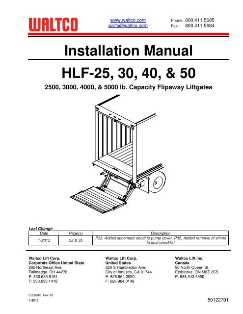
www.waltco.com Phone: 800.411.5685parts@waltco.com Fax: 800.411.5684<strong>Installation</strong> <strong>Manual</strong><strong>HLF</strong>-<strong>25</strong>, <strong>30</strong>, <strong>40</strong>, & <strong>50</strong><strong>25</strong>00, <strong>30</strong>00, <strong>40</strong>00, & <strong>50</strong>00 lb. Capacity Flipaway LiftgatesLast ChangeDate Page(s) Description1-2013 33 & 35P33, Added schematic decal to pump cover, P35, Added removal of shimsto final checklist<strong>Waltco</strong> Lift Corp. <strong>Waltco</strong> Lift Corp. <strong>Waltco</strong> Lift Inc.Corporate Office United State United States Canada285 Northeast Ave. 620 S Hambledon Ave. 90 North Queen St.Tallmadge, OH 44278 City of Industry, CA 91744 Etobicoke, ON M8Z 2C5P: 3<strong>30</strong>.633.9191 P: 626.964.0990 P: 888.343.45<strong>50</strong>F: 3<strong>30</strong>.633.1418 F: 626.964.0149EO:6918 Rev 101-2013 80122701
Table of ContentsImproper installation of this liftgate could result in severe personal injury ordeath.Read and understand the contents of these instructions before proceeding.When installed, this liftgate must not alter or prevent vehicle compliance to anyexisting state or federal standards.Each chassis manufacturer’s recommendations should be consulted forcompliance.Introduction ................................................................................................3Safety Information ................................................................................................4Liftgate Terminology ................................................................................................6Basic Mounting Requirements ........................................................................................9<strong>Installation</strong> .......................................................................................................................10Placement of Decals ................................................................................................32Lubrication Instructions ................................................................................................34Final Inspection ................................................................................................35How to Order Parts ................................................................................................51Optional Kit Instructions:Hand Held Remote Kit ................................................................................................35Kit #800004<strong>30</strong>Aux Dual Cable Battery Kit (Truck) ................................................................38Kit #80001066Dual Cable Kit (Trailer) ................................................................................................39Kit #80001069Dual Control Kit ................................................................................................43Kit #80000437Cab Shut-Off Kit ................................................................................................44Kit #80000827Underride Kit ................................................................................................45Kit #22796001 & 22796002Walk Ramp Kit ................................................................................................46Kits #22766001 & 22766002Chain Anchor Kit ................................................................................................49Kit #2274<strong>50</strong>01Page 2
IntroductionIf anyone observes improper installation, improper operation, or damage, they should immediatelycontact a qualified person for assistance and correction. We strongly urge anyone that has anyquestions or doubts as to the installation, condition, use, operation, maintenance or repair of the liftgateto contact us at <strong>Waltco</strong> where we have qualified personnel that will be happy to assist you. Telephonenumbers and addresses of these locations are listed in the Owner’s <strong>Manual</strong> and <strong>Installation</strong>Instructions.INSTALLATION<strong>Waltco</strong> liftgates should only be installed by those with sufficient basic skills to understand theinstallation and operation of the liftgate, along with the equipment on which the liftgate is beinginstalled. <strong>Waltco</strong>’s installation instructions are not intended to give rationale for all the instructions thatare given; however, it is the intent of these instructions to give the installer both the operations andwhat we believe to be the most desirable sequence of implementing these operations. Theseinstructions can in no way expand into an area where they will replace a qualified person, or clearthinking and a basic knowledge that must be possessed by the installer.It has been our experience that a knowledgeable journeyman following these instructions andobserving the operation of the liftgate will have a sufficient comprehension of the liftgate to enable thisperson to troubleshoot and correct all normal problems that may be encountered.Failure to follow the installation instructions, adjustments and mounting dimensions may result inimproper and unsafe operation of the liftgate. Unauthorized alterations of the liftgate can cause anundesirable and dangerous condition.OWNER’S MANUALThe <strong>Waltco</strong> Owner’s <strong>Manual</strong> is intended to act as a guide for operation and routine maintenance butis no way intended to encourage usage or repair of the liftgate by those who are not qualified to do so.The contents of the owner’s manual include, but are not limited to general operation instructions,routine lubrication, parts lists, and an outline of things that should be checked but may not be obviousto those not technically qualified. This manual assumes the liftgate is properly installed, undamagedand operates correctly. Improper installation, improper operation, or damage should be immediatelycorrected by a qualified person.INSPECTIONAs part of the regular inspection of a liftgate and after damage or suspicion of an overload, inspectfor wear or structural damage and make necessary repairs or replacements. Check all structuralcomponents and their attachment to the liftgate for cracked welds, loose fasteners, wear and partdeformation. Check cylinder and hose for leaks. Inspections and repairs should be made by a qualifiedmechanic.REPLACEMENT PARTSUse only <strong>Waltco</strong> original equipment replacement parts. Components of other liftgate manufacturersmay outwardly appear to be the same but are not interchangeable with <strong>Waltco</strong> products. <strong>Waltco</strong>components are specifically designed for safety requirements, reliability and compatibility with ourproducts. Refer to your <strong>Waltco</strong> parts manual when ordering parts. NOTE: When ordering, give modeland serial number of liftgate.DECALSIt is important that every vehicle that has a WALTCO Liftgate have legible DECALS clearly posted onthe vehicle and an OWNER’S MANUAL in the vehicle at all times as a guide for proper operation andmaintenance.Additional DECALS and OWNER’S MANUALS can be obtained from WALTCO LIFT CORP.Page 3
Chapter 1Safety InformationWARNINGRead, understand, and follow all of the warning listed below.Failure to follow these warning could result in severe personal injury or death.• Read and understand the Owner’s <strong>Manual</strong>, all decals and warning on liftgate before operating liftgate.• Do not operate liftgate without a thorough knowledge and understanding of the operation of the liftgate.• Liftgate hazards can result in crushing or falling.• This liftgate is designed for loading and unloading of cargo. If personnel are required to ride liftgate, observeand familiarize yourself with the liftgate operation, decals and manuals. Ensure stable footing at all times.• Do not ride liftgate with unstable loads.• Wheeled loads must be properly retained from rolling.• Tall, high center of gravity loads must be retained from falling over.• Never overload liftgate:Load platform as close to the vehicle, and towards the middle of the platform as possible. Refer to owner’smanual and capacity decal of liftgate for maximum load and load placement.• Keep hands and feet clear of all potential pinch points.• Never use liftgate if it makes any unusual noise, has unusual vibration, raises or lowers unevenly, or fails tooperate smoothly.• Never use liftgate if it shows any signs of structural damage such as cracked welds, bent or distortedmembers.• Do not attempt any repairs unless you are qualified to do so. Care should be taken when work is performedon a disabled liftgate located near moving traffic. When possible the vehicle should be moved away fromtraffic areas for repair. Precautionary measures should be taken to ensure personal safety including thoserecommended in Federal Motor Vehicle Safety Standards 571.1<strong>25</strong>.• When welding to liftgate, or liftgate components, take all necessary safety precautions, including usingrespiratory protection and other pertinent personal protective gear when welding harmful materials.• All protective covers, guards, and safety devices must be in place and access doors closed before operatingliftgate.• Do not allow anyone to stand in, or near area, in which Platform will open and close before opening or closingPlatform.• Do not allow anyone to stand near the Platform where a falling load could land on them.• Platform is always to be properly stored and secured for transit. See the Owner’s <strong>Manual</strong> for details.• Take care to retain cargo during transit for liftgate Platforms which function as the tailgate or door of the cargoarea. Small objects can fall through the space between the vehicle and the folded Platform.• A Lock-Out device or Shut-Off Switch should always be used to prevent unauthorized use of liftgate.• For liftgates with Runners, never use liftgate if Runners do not travel freely and smoothly.• For liftgates with Roller Lifting Chain, the Chain should be replaced every (5) five years or 15,000 cycles,whichever comes first. Replace only with <strong>Waltco</strong> approved Roller Chain.• Never transfer loads which exceed lifting capacity on or over any part of the Platform unless the liftgate isequipped with a special reinforced Platform and Platform Support Bars for use when the Platform is used asloading ramp (dock board). Refer to the “Using Platform as a loading ramp” Chapter in the OperationInstructions of the BZ/RZ series Owner’s <strong>Manual</strong>.• For liftgates equipped with Trailer Hitches, never exceed the rated capacity of the hitch. Do not exceed thevehicle’s weight rating. Refer to the vehicle’s Owner’s <strong>Manual</strong>.• Vehicle must comply with all state and federal standards.• Follow the “Maintenance Guide” chapter in the Owner’s <strong>Manual</strong>.Page 4
Liftgates with Tilt Function• Proper use of the Control Switches is of extreme importance.• Improper use of Tilt Switch could cause load to fall from the Platform or damage the liftgate.• Platform should be in a generally horizontal position when raising or lowering with a load.• In any tilt position, the Platform may vary from level while raising or lowering the Platform.Liftgates equipped with spring operated Cam Closer• Replace Cam Release Spring every five (5) years or 15,000 cycles, whichever comes first.RGL-Series Liftgates• Make certain Platform Brake mechanisms are operating properly.• The Runners are always to remain powered up against the Up-stops Pins when in transit.• Inspect Cables every three (3) months or 7<strong>50</strong> cycles, whichever comes first. Cables must be replaced if theyshow signs of wear, distortion, kinking or if any broken wires are visible• Replace cables every five (5) years or 10,000 cycles, whichever comes first.This is the safety alert symbol. This manual uses this symbol to alert you to potential personal injuryhazards.Obey all safety messages that follow this symbol to avoid personal injury or death.SIGNAL WORDSWARNINGIndicates a potentially hazardous situation, which if notavoided, could result in death or serious injury.Black letters on an orange backgroundCAUTIONIndicates a potentially hazardous situation, which if notavoided, may result in minor or moderate injury. Mayalso be used to alert against unsafe practices.Black letters on a yellow background.NOTICEIndicates a potentially hazardous situation, which if notavoided, may result in property damage.WARNINGCAUTIONNOTICEPage 5
Chapter 2Liftgate Terminology1. Hydraulic Cylinder2. Hose Assembly3. Hose Guard4. Dual Hose Clamp5. Pump Unit Starter Solenoid6. Breather Cap7. Lowering Valve Coil8. Raise Valve Coil9. Bulkhead Elbow, 90 Deg.10. 90 Deg. Hose Fitting11. Tee, Hose Fitting12. Drain Plug13. Pump14. Thermal Switch (Inside Motor)15. Ground Cable16. Pump Unit Motor17. Pump Unit Reservoir18. Lock Valve10422942161785371811913141611512GR02778Page 6
Chapter 2Liftgate Terminology19. Mount Tube Assembly20. Parting Bar Assembly21. Deck Assembly22. Torsion Bar23. Deck Extension Assembly24. Lift Arm Assembly<strong>25</strong>. Folding Assist Springs26. Parallel Arm27. Pump Box28. Mount Plate29. Spec Tag<strong>30</strong>. Bed Extension31. Dock Bumper32. Transit Chain<strong>30</strong>202832192322212429<strong>25</strong>273126GR02779Page 7
Chapter 2Liftgate TerminologyExplanation of Specification TagModel Name Description Capacity<strong>HLF</strong> Twin Cylinder <strong>25</strong>00 lb.<strong>HLF</strong> Twin Cylinder <strong>30</strong>00 lb.<strong>HLF</strong> Twin Cylinder <strong>40</strong>00 lb.<strong>HLF</strong> Twin Cylinder <strong>50</strong>00 lb.MODEL NAMERATED CAPACITYBased on an evenlydistributed load on theplatform flat surface.SERIAL NUMBERof liftgate. To be usedwhen ordering parts orwhen contacting <strong>Waltco</strong>for service or warrantyquestionsDATE OFMANUFACTUREMonth / YearGR00241SpecificationTagGR02837Page 8
Chapter 3 Determine Basic Mounting RequirementsMeasure distance from ground to floor level. This isthe bed height.Refer to bed height dimension on mounting chartto determine basic mounting dimension “A” andminimum mount frame clearance required.NOTE:Max bed height dimensions for unloaded vehicle.Min bed height dimensions for fully loaded vehicleNOTE:Tire clearance should be 6” minimum between tireand mount frame.Bed Height(Ground to Floor)GR00139STANDARD BED HEIGHT MODELSMOUNTING CHARTBed Height “A” Dimension Mount Frame Clearance46”-57” <strong>25</strong>-1/2” 35-1/2”57”-60” 26-1/2” 34-1/4”81 3 81239 5 841 3 478A - DIM17CENTER LINEOF LIFTGATEMOUNT FRAMECLEARENCEGR02781Page 9
Chapter 4<strong>Installation</strong>PREPARATION OF BODY SILLRemove all obstructions that would interfere withoperation of Liftgate; such as dock bumpers, trailerhitches, projections, etc.“X”Locate and mark the center of body sill.NOTE:All mounting measurements for centering liftgatewill come from centerline mark.Body sill must have clearances indicated. Cut or notchRear Sill to obtain these clearances.Refer to chart p. 3-1PlatformWidth +2”Hold “X” as follows:“A” Dimension“X” Max.<strong>25</strong>-1/2” 6”26-1/2” 7”GR02184Additional Notching.Additional notching of the rear sill may be necessary onunits with larger sills.GR02782Cut away vehicle frameas required to obtain theminimum clearanceindicated.46” TO 57”BED HEIGHT<strong>25</strong>-1/2”“A” DimensionGR02783Page 10
Chapter 4<strong>Installation</strong>Cut away vehicle frameas required to obtain theminimum clearanceindicated.57” TO 60”BED HEIGHT26-1/2”“A” DimensionsGR02784Cap Vehicle Frame, using a 3/16” or 1/4” X 2” steelstrap.Body CrossmemberVehicle Frame3/16” or 1/4” x 2”steel strapGR006<strong>25</strong>INSTALLATION OF BED EXTENSIONIf bed extension is to be bolted on, use pattern at rightfor drilling holes.Thirteen (13) 9/16” diameter holes required.GR02905Page 11
Chapter 4<strong>Installation</strong>Position Bed Extension up to rear sill using a forklift orcrane.Make certain bed extension is centered on vehicle bodyand level with bedOther means may be used to support BedExtension in position. ALWAYS verify thesafety of your supporting method beforeproceeding.Bed ExtensionGR02647IF BOLTING:Bed extension to sill, use thirteen (13) 1/2” bolts, nutsand washers provided with kit.Torque bolts to 90 ft. lbs.IF WELDING:NOTE:To help protect vehicle paint, notches have beenprovided so top of bed extension does not have tobe welded.NOTE:If corner posts of vehicle body extend beyond rearsill of body, shims may be added behind bedextension to prevent bowing of bed extension.Weld underside of Bed Extension.Weld all Notches 100% with 1/8” weld to rear sill ofvehicle body.Weld under the side bars and all gussets with 1/8” weldx 2” long.NotchesBottom of GussetsBottom of Side BarGR02648Page 12
Chapter 4<strong>Installation</strong>ALTERNATIVE WELDING OF BED EXTENSIONWeld top side of bed extension, 1/8” x 2” welds overeach of the notches on underside of extension.Weld under the side bars and all gussets with 1/8” weldx 2” long.1/8” weld x 2” long aboveeach of the notchesUnder GussetsUnder Side BarsGR02647 & 48Remove liftgate from shipping pallet, and all banding.Do not unfold platform until instructed to do so.Mounting Bar(Each Side)STOP Before proceeding; verify vehicle bedheight and A-dimension to be used!Refer to Chapter 3 of this manual.NOTE:If mounting to 26-1/2” A-Dimension, the MountingBars will need to be removed before proceeding. Donot remove the Auto Tilt Wedge Blocks.Auto Tilt WedgeBlock (Each Side)Mount Bars are set for <strong>25</strong>-1/2” A-Dimension whenshipped from factory.Do not remove Mounting Bars until instructed to do so.Unfold platform to open position.GR02785Page 13
Chapter 4<strong>Installation</strong>Position liftgate up under vehicle.Using a forklift or crane, raise platform up to bedextension.Ensure 3/16” coil pins are between platform and bedextension skins.Platform to be centered on vehicle, and level with floor(bed) of vehicle.A jack can be used to help position mount tube to properA-Dimension.Be sure platform is centered on vehicle body and bedextension.Other means may be used to supportLiftgate in position. ALWAYS verify thesafety of your supporting method beforeproceeding.Position platform so it is level with vehicle body, andverify proper A-Dimension.NOTE:If unable to obtain correct A-Dimension withplatform level, it may be necessary to screw in thePlatform Adjustment Bolts as shown below.Platform and Mount Tube should be level.Centerline of body, bedextension and platformBed ExtensionPlatformPlatform3/16” ShimBed Extension3/16” Coil Pin forshims2 placesA-DimGR02786 & GR02787 & GR02937Page 14
Chapter 4<strong>Installation</strong>Bolts heads should be contacting platform hinges, if theyare not, ensure the platform and mount tube are parallelprior to adjusting.Note:Platform springs are engaged and under tension.Take care when adjusting liftgate.PlatformAdjustment BoltGR02660Use two 3” channels (tubes, or similar), lay on vehiclefloor and clamp to bed extension and platform asshown.Install counter weight on channels as required.Platform is to be held parallel with vehicle floor, and is toshimmed 3/16” away from bed extension, centered withvehicle body.Channel3/16” ShimsCounterWeightOther means may be used to supportLiftgate in position. ALWAYS verify thesafety of your supporting method beforeproceeding.IMPORTANT:Verify mount tube is at correct A-Dimension beforeproceeding to next step:• Correct A-Dimension for bed height• If using 26-1/2” A-Dimension and nomounting bar, square up mount tube withground by temporarily powering the gate toobtain the correct A-Dimension.PlatformBedExtensionGR02788CONFIRM PROPER MOUNT PLATEHigher capacity liftgates (<strong>40</strong>00# & <strong>50</strong>00#)must use 5/8”Mount PlateFor <strong>25</strong>00# & <strong>30</strong>00#(2 notches)For <strong>40</strong>00# & <strong>50</strong>00#(1 notch)3/8" 5/8"Confirm the capacity and mount plate profiles match thepicture to the right.Contact <strong>Waltco</strong> immediately if you have a high capacityliftgate with the wrong mount plate.GR02899Page 15
Chapter 4FOR GALVANIZED, BOLT-ON MOUNT PLATESAlign mount plates with outside surface of brackets onmount tube. Loosely install all of the ¾” diameterhardware to hold mount plate in position.<strong>Installation</strong>¾” dia hardwareTorque to <strong>25</strong>0 -<strong>30</strong>0 ft-lbsMount plateto be onoutside ofbrackets.Once aligned, weld mount plates to chasis frame perinstructions below.Tighten hardware after welding to <strong>25</strong>0-<strong>30</strong>0 ft-lbs.GR02907MOUNT PLATE INSTALLATIONLocate mount plates on mount tube. Mount platesshould be approximately 90° to vehicle frame.Check that mount plates extend a minimum of 5-1/4"above bottom of vehicle frame. If dimension cannot beheld, refer to the optional installation.3/8” weld 100%, threesides of Mount PlatesShield all wires and hoses from heat andweld splatter.Recheck “A” dimension. Weld three sides of mountplates 100% to vehicle frame with 3/8” weld.For Non-Galvanized units:Weld mount tube to the mount plates. Weld all around,both sides of the mount plates, and ends, with 3/8" weld.5-1/4”Min.MountTubeMountPlateNon-Galvanized:3/8” weld 100%,all around bothsides and endsTo avoid injury or property damage, do notremove clamps from deck. Use forklift,crane, or other safe means to support deckand then remove clamps.GR02789Page 16
Chapter 4OPTIONAL INSTALLATIONIf the 5-1/4” dimension cannot be met a 3/8” thickplate must be added.Shield all wires and hoses from heat andweld splatter.<strong>Installation</strong>3/8” weld 100%, threesides of mount plate andadapter plates as shown.5-1/4”Min.Recheck “A” dimension. Weld three sides of mountplates and three sides of 3/8” plate 100% with 3/8” weld.For Non-Galvanized units:Weld mount tube to mount plates. Weld all around, bothsides of mount plates, and ends, with 3/8" weld.To avoid injury or property damage, do notremove clamps from deck. Use forklift,crane, or other safe means to support deckand then remove clamps.5-1/4”Min.3/8”AdapterPlateNon-Galvanized3/8” weld 100%, allaround both sides andends of mount plates.GR02790NOTE:If necessary, liftgate may be mounted to inside offrame as shown.One 8” to 12” channel or two5” to 6” channelsTruck FrameWeld channelto Truck Framewith 3/8“ weld.Weld 100% allaround asshown.5-1/4” Min.37” or widerWeld Mount Plate tochannel with 3/8” weldafter channel is weldedto the Truck Frame.GR02791Page 17
Chapter 4<strong>Installation</strong>INSTALLATION OF CONTROLSLocate switch such that, when operating liftgate,operator will have clear view of entire platform area andwill not be in area that liftgate will pass through.Use this template to locate screw holes, and hole forcontrol cord.GR02662If Control Cord will be run through a hole of body,remove all sharp edges from hole.Use 1/4” Self-tapping Screws to secure switch.1/4-20 SelfTapping ScrewsCorner PostControl CordGR02761Page 18
Chapter 4<strong>Installation</strong>Route control cord into pump enclosure, using grommetsupplied.Hints:With grommet loose, insert largest terminal of controlcord through the grommet first, then the others.Apply a drop or two of oil on grommet to help insertterminals through grommet, and to install grommet intopump enclosure.GrommetControl CordConnect control cord to pump unit as shown. Terminalsare gendered to allow only correct connections.PumpEnclosureNote: Some components not shown for clarity.GR02765INSTALLING BATTERY CABLESRoute both power and ground cables into pumpenclosure using grommets as shown.Note: The power cable has red ends, ground cable is allblack.Power cable is bolted to either one of the solenoids andcopper bus bar.Ground cable is bolted to pump unit side, with LockValve ground wire.Route power and ground cables along truck chassis,towards truck batteries, securing them every 24” withcable ties provided.Do not connect any cables to batteries at this time.Be certain cables are protected withgrommets when passing through metalholes or over sharp edges.GrommetsLock ValveWiresGround Cable(Black)Power Cable(Red)SolenoidNote: Some components not shown for clarity.GR02765Page 19
Chapter 4INSTALLATION OF TERMINAL LUGStrip 1” to 1-1/4” of insulation from end of cable.Slide heat shrinkable tubing onto cable.Insert bare wire into compression nut until it seats.IMPORTANT: Be sure to use correct compressionnut, use 1&2 gauge nut for 1 gaugecable, use 0 gauge nut for 0 gaugecable.Note: Copper wire should be flush with, or slightly pastnut<strong>Installation</strong>Heat shrinkable tubingbefore installationCompression Nut1” 7/8” – 1-1/4” to 1”GR00299Grip nut with wrench and turn terminal until nut seatsGR00<strong>30</strong>0Position heat shrinkable tubing over terminal and end ofcableBeads of SealantShrink tubing using electric heat gun or torch.Note: To reduce chance of damaging tube andcable, a heat gun is recommendedApply sufficient heat to produce thin bead of sealant allaround tube edgesHeat ShrinkableTubingGR00<strong>30</strong>1Page 20
Chapter 4INSTALLATION OF POWER CABLESThese instructions are for connecting to truckbatteries only. Refer to auxiliary batteryinstructions in back of this manual.Locate and mount circuit breaker directly to batteriesusing copper terminal link supplied.Circuit breaker must be mounted to give good protectionagainst any objects coming into contact with circuitbreaker terminals and causing a short. Position mustalso be readily accessible to reset breaker.NOTE:Circuit Breaker is to rest solidly on batteryto prevent vibration during transit.If unable to connect circuit breaker direct to batteries,an optional jumper cable can be made from excessivelength of power cable, see instructions above forinstalling terminal lugs.Connect power cable (positive) from liftgate to circuitbreaker. Then connect ground cable to negativeterminal on batteries.Apply a generous amount of Dielectric Grease to allBattery terminals and Circuit Breaker terminals.<strong>Installation</strong>Circuit BreakerBattery Cables fromLiftgateCopper Terminal LinkProtect wires from any sharp edges orholes that may abrade insulated coveringof wires.Secure battery cable so it does not comenear, or in contact with, other vehiclewiring, fuel lines, brake lines, air hoses,exhaust system, etc.Vehicle BatteriesIMPORTANT:DO NOT operate liftgate until Mounting Bar hasbeen removed.GR02764Page 21
Chapter 4Electrical Schematic<strong>Installation</strong>GR02798DIVERT WATER FROM ENCLOSUREZip TieTo help prevent channeling water into pump or batteryenclosures:• Secure hoses, cables and cords downward asthey exit the enclosure.• If a downward exit is impractical, a Zip Tie canbe installed around hose or cable to helpinterrupt the flow of water as shown.Flow of waterPump or BatteryEnclosureGR02460HOSE INSTALLATIONAvoid twisting of hoses.High PressureNo PressureAvoid sharp bends when routing hosesHoses will contract under pressure. Allow plenty of slackbetween connecting points.Do not clamp hoses at bends to allow for lengthchanges when hose is pressurized.GR00717Page 22
Chapter 4REMOVE MOUNTING BAR, WEDGE BLOCKS, AND3/16” COIL PIN SHIMSInsure platform is properly supported beforedisconnecting the Mounting Bars and Wedge Blocks.<strong>Installation</strong>Mounting Bar(Each Side)Do not be under platform or lift arms whendisconnecting the Mounting Bar.Access bar from forward side of mounttube.Remove two 3/16” coil pins from platform at springretainer.Coil PinsAuto Tilt WedgeBlock (Each Side)GR02785FILLING HYDRAULIC RESERVOIRPosition liftgate deck into raise position (use forklift,crane, or other safe device if necessary).Remove Reservoir Plug.Oil level should be 1/2” from top of reservoir in raisedposition.If low, fill as required.Replace Plug with Breather.Run liftgate full cycle several times to release trappedair from system.Replace capwith BreatherGR02792Page 23
Chapter 4Hydraulic Schematic<strong>Installation</strong>Lock ValveLoweringSolenoidValveRaiseSolenoidValveGR02797Recommended FluidsFill reservoirTemperature Range Acceptable Fluids • Fill with recommended fluid or equivalent.0° to 120° F <strong>Waltco</strong> Biodegradable • Fill the reservoir to within 1/2” from the top.Liftlube TM part #85803860 • Fluids are available from the <strong>Waltco</strong> partsShell Tellus S2 V 32Dept. 1-800-411-5685 www.waltco.comChevron AW32-20° to 90° F <strong>Waltco</strong> BiodegradableLiftLube Arctic part#85803866NOTE:Do not use the following fluids:Shell Tellus S2 V 15Mobil DTE 13MIL – H - 5606Brake FluidPower steering fluidAutomatic Transmission Fluid (ATF)A good quality SAE 10W motor oil may also be used intemperatures above 32° F.Page 24
Chapter 4There is no speed adjustment on this liftgate.Lowering speed is controlled by the pressurecompensative valve plumbed into the pump.Regardless of weight on platform, liftgate should lowerat approximately six (6) inches per second.<strong>Installation</strong>Bed Height (inches)6= Lowering Time (seconds)This liftgate must have the pressurecompensative valve installed in the pump.Pressure CompensativeFlow Control Valve insidePumpGR02792ADJUSTMENT OF PARTING BARIMPORTANT:Parting bar and rubber snubbers MUST be installedbefore attempting to fold platform and raise to storedposition.The snubbers are necessary to protect platform fromcontacting the chassis frame and damaging paint onplatform.PARTING BAR 1 – This PagePARTING BAR 2 – Next PageNOTE: Identify parting bar supplied and proceed toproper instructions.PARTING BAR 1:To assist the opening of the platform:If vehicle is 52” or less without walk ramp, proceed tonext page of instructions.Hole 1 (As shipped):For vehicles with no walk ramp.Hole 2:For vehicles with walk ramp or vehicle bed heightexceeds 57”.¼” 100% weldafter locatedParting Bar2 to 18degree leanPlatform is to lean in towards parting barwhen at ground. It is not to fall open toground.Hole 1Hole 2GR02799Page <strong>25</strong>
Chapter 4Roller Bracket Adjustment: (For bed heights above52” and all walk ramp applications)Verify roller bracket is in correct orientation for bedheight of vehicle and walk ramp application.If needed, remove all (3) three bolts to re-orientate theroller bracket as show for correct application.NOTE: Platform must lean towards parting barbetween 2 and 18 degrees.IMPORTANT:Improper installation of parting bar can result indamage to the liftgate platform, by powering into thechassis frame of vehicle.WELD PARTING BAR AFTER FUNCTIONALITY ISCONFIRMED. ¼” WELD 100%<strong>Installation</strong>23"<strong>25</strong> 3 4 "For Bed Heights of 52” or lowerFor Bed Heights above 52”Also used if vehicle has a walk rampGR02800PARTING BAR 2:To assist the opening of the platform:Vehicles without walk ramp:Lower platform to ground with slight tilt towards vehicleas shown. Slide parting bar to platform and bolt intoplace.Vehicles with walk ramp:Locate parting bar in hole closest to mount tube and boltinto place.Tighten nuts and bolts to <strong>50</strong> ft lbs.Platform is to lean in towards parting barwhen at ground. It is not to fall open toground.Parting BarWalk Ramp Position2 to 18degreeleanGR02900Page 26
Chapter 4ADJUST PLATFORM TILTAdjust bolts between Stop Block and Platform Hingeto achieve 1” - 2” tilt up of platform as shown. Agreater tilt up is recommended for higher capacities.<strong>Installation</strong>1” - 2”NOTE:Adjust both Stop Block Bolts evenly.Tighten Jam Nuts.Jam NutAdjustmentBoltGR02668, GR02690Page 27
Chapter 4INSTALLATION OF RUBBER SNUBBERS<strong>Installation</strong>Rubber snubbers are important for holding the platformtight in stored position. If platform, deck and deckextension are not tight excessive ware can occur.Raise platform up 1” below the bed extension as shown.Note:Take care not to fully raise platform so as to contactchassis frame and damage paint on platform.Locate Rubber Snubber flat against deck tube or againstthe aluminum extrusion as shown.Weld one Snubber in place and check operation:Check that snubber holds platform tight.Check that platform clears snubber whileopening.Weld second snubber on opposite side of chassisframe.Note:Weld snubbers to mount plate or chassis frame asrequired. Steel angle of snubber may be trimmed asneeded.After installing parting bar and snubbers, carefully runliftgate up to stored position and verify platform clearsthe chassis frame cutout (see beginning of this chapter).Locate snubber flat againstplatform cross tube or against thealuminum extrusion as shown¼” weld x 2” long1"GR02793Page 28
Chapter 4<strong>Waltco</strong> offers three suggestions for the installation of thevehicle taillights. We believe these suggested locationsmeet D.O.T. regulations but do not warrant that they do.Your installation of the vehicle taillights should meet allapplicable regulations and requirements. This is in noway to infer that these suggestions are the only correctmethod of installing taillights.<strong>Installation</strong>Location “A”Location “B”Location “A”: Mount lights above bed extension and tothe rear of the body rear corner posts.Location “B”: Mount lights into the rear corner posts.<strong>Waltco</strong> also offers dock bumpers with lights preinstalled.IMPORTANT:All lights must be installed in accordance with allapplicable D.O.T. regulations.GR02762INSTALL DOCK BUMPERSSlip dock bumpers on to bed extension.Bolt bumpers to bed extension using four 5/8” bolts,washers and lock washers.Bed ExtensionTorque bolts to 167-179 ft. lbs.Bolts WashersDock BumperGR027<strong>40</strong>Page 29
Chapter 4INSTALL BRACES<strong>Installation</strong>Bolt brace and support angles as shown.Support angle to span a minimum of 3 or 4crossmembers.Note:It may be necessary to trim rearward end of supportangles to clear rear sill and/or dock bumper.Weld support angles to all crossmembers it contactswith minimum four (4) inches of 1/8” weld.Support Angle *Brace Angle *GR02921After installation of dock bumpers, ground clearance needs to be considered. If dock bumper steps are too low,they may hit the ground when driving in or out of driveways, etc.Adjust dock bumper steps to achieve recommended ground clearance of 20” – 24” as shown below.Note: Overhangs greater than 11 feet may need dock bumper steps set higher to maintain a 10º departure angle.Use formula below to calculate ground clearance.Bed heights below 46” may require the lower step to be completely removed to achieve sufficient groundclearance.Ground Clearance20" - 24"Calculate Ground Clearance for 10ºdeparture angle:Ground Clearance = Overhang x .176OVERHANG (inches)GR02896Page <strong>30</strong>
Chapter 4STEP ADJUSTMENT<strong>Installation</strong>Steps for non-light dock bumpers can be lowered bysimply unbolting and lowering to desired setting.For dock bumpers with lights, it will be necessary toinstall steps.1. Determine correct step height per aboverecommendations.2. Identify hole set required for bolting intoposition.3. Cut off step legs just above hole set required.4. Bolt into position as shown.Torque bolts to 34-37 ft. lbs.Cut both legs justabove holes to beused for boltingGR02744Page 31
Chapter 5Placement of DecalsTo order complete set of <strong>HLF</strong>-Series liftgate decals, order kits below:<strong>HLF</strong>-<strong>25</strong> = Kit part number 800021<strong>30</strong><strong>HLF</strong>-<strong>30</strong> = Kit part number 80002131<strong>HLF</strong>-<strong>40</strong> = Kit part number 80002132<strong>HLF</strong>-<strong>50</strong> = Kit part number 80002133Page 32
Chapter 5Placement of DecalsAll decals must be in place and legible or all warranties are void.ITEM DECAL QTY PART NO. LOCATION123Safety InstructionsOperationHazard DecalImportant DecalMotor Thermal Switch11111801008<strong>50</strong>80101528801013708010082880101480Locate in a conspicuous place near controls.If your liftgate is equipped with dualcontrols, an additional Safety Instructiondecal (801008<strong>50</strong>) is to be placed in aconspicuous place near the second set ofcontrols.Stand Clear Decal 1 7<strong>50</strong>89296Capacity Decal-<strong>25</strong>00lb 1 80100<strong>25</strong>5Capacity Decal-<strong>30</strong>00lb 1 80100<strong>25</strong>7Capacity Decal-<strong>40</strong>00lb 1 80100260Capacity Decal-<strong>50</strong>00lb 1 80100263Use Handle Decal 1 7<strong>50</strong>89295Stand Clear Decal 1 7<strong>50</strong>89296Capacity Decal-<strong>25</strong>00lb 1 80100<strong>25</strong>5Capacity Decal-<strong>30</strong>00lb 1 80100<strong>25</strong>7Capacity Decal-<strong>40</strong>00lb 1 80100260Capacity Decal-<strong>50</strong>00lb 1 801002634 Circuit Breaker Decal 1 80100829Refer to the following diagram showing decal locations.Locate on curbside of platform(Position so as to be read when platform is open)Locate near platform handle(Positioned so as to be read when platformis being unfolded into loading position)Locate next to liftgate circuit breaker.In applications where more than one circuit breakeris used, this decal must be placed in both locations5 Stand Clear Decal 1 7<strong>50</strong>89296 Locate on driver’s side of vehicle body near liftgate6 Schematics Decal 1 80101622 Locate inside of pump box coverTo maximize decal adhesion to surfaces:• Surface must be dry and clean• Firm pressure must be applied to decal• Minimum surface temperature 65ºHeat gun may be used to heat surfaceGR029<strong>40</strong>Page 33
Chapter 6Lubrication InstructionsThe liftgate should be lubricated every 120 days.#1 – Grease all grease fittings in pins and cylinders with grease gun.#2 - Oil with a light weight machine oil (do not use on bearings in platform).21112GR02794Page 34
Chapter 7 FINAL INSPECTION SHEETIMPORTANT:All of the following are to be checked and verifiedbefore installation is complete.A. Are all pivot pins secured with retaining boltand lock washer?B. Are all roll pins securely in place?C. Does liftgate fold and unfold properly?D. Does the platform meet the vehicleproperly?P. Are all decals properly in place and legibleaccording to the decal placement drawings?Q. Is pump cover installed and securelylatched?R. Is the owner’s manual in the vehicle?S. Are 3/16” coil pin shims removed fromplatform?E. Do controls operate properly?F. Are bed extension, mount frame, mountplates, dock bumpers, bumper braces,taillight guards and taillights all finishwelded?G. Are hydraulic hoses and fittings properlyconnected with no leaks?H. Is battery cable attached and clampedtight?I. Is circuit breaker installed at battery?J. Are all electrical connections coated withdielectric grease?K. Has hydraulic system been properly bledof all air?L. Is pump reservoir full of oil and capped withbreather plug?M. Are all parts properly lubricated accordingto the lubrication instructions?N. Do lights operate properly(Note: Lights must be installed inaccordance with all applicable stateand federal D.O.T. regulations)O. Is license plate properly installed?WARNING:Do not use liftgate if any of the above are notchecked and verified. If you have any questionsnot covered in this manual, contact your nearest<strong>Waltco</strong> distributor, or the nearest <strong>Waltco</strong> factory.Page 35
Hand Held Remote <strong>Installation</strong>DRILL SOCKET HOLESUsing dimension shown, drill mountingholes in desired location for socket.1-1/4” DIA.7/32” DIA.GR00036INSTALL SOCKETAssemble socket as shown.Install wires according to colors:W = White (Raise)B or BK = Black (Lower)G = Green (Power)GR022<strong>40</strong>CONNECT WIRES TO PUMP UNITThis step is for most liftgates, see nextpage for MDL series liftgate instructions.Route Control Cord into pump enclosure.First connect Pump wires to Dual ControlAdapter Harness as shown.Connect both Control Cords to other ends ofAdapter Harness as shown.Note!Match wire connections male to female. Colorof wire may vary.CONTROLCORDADAPTORHARNESSCONTROLCORDSOCKETGR0208280101485 EO6447 Rev.04Page 36
Hand Held Remote <strong>Installation</strong>LPF Liftgate InstructionsLoosen cover bolt and remove Access Coverfrom center of Mount Tube.Remove Plastic Plug in top of Mount Tubeand insert Strain Relief Fitting through thesame hole. Tighten plastic Mounting Nut.MOUNTINGNUTSTRAIN RELIEFPLUGGR00335Remove Strain Relief cap nut and slide capnut over Control Cord.Insert Control Cord into Mount Tube throughStrain Relief, pushing one wire connectorthrough at a time.GR00336Route Control Cords behind Battery Cable,keeping them close to back wall of MountTube and away from battery cable stud(Contact between any connectors and batterycable stud could result in a short circuit).BATTERYCABLECONTROLCORDSConnect both Control Cords to three wayDual Control Adapter Harness.NOTE:Match wire connections male to female.Color of wire may varyADAPTERHARNESSGR00337Pull unsupported lengths of Control Cord out ofMount Tube and thread Strain Relief cap nutson snuggly. Do not over-tighten cap nuts, asthis may damage the wires.CABLE TIESUsing 8” cable ties provided, secure ControlCords to Hose Fittings as shown.Secure Control Cords to vehicle with 16”cable ties.GR0033880101485 EO6447 Rev.04Page 37
Hand Held Remote <strong>Installation</strong>MDL, MDLBG, SB, PTN, SB & DT LiftgateInstructions:Route Control Cord 10099332 into crossbeambox.Disconnect green wire of existing controlswitch from valve solenoid.Connect 10098429 to valve solenoid.Connect green wires on existing control switchand on 10099332 to 10098429 as shown.Connect white and black wires on 10099332 tosame places the black and white wires onexisting control switch connect.Note!Match wire connections male to female. Colorof wire may vary.GR0280480101485 EO6447 Rev.04Page 38
Auxiliary Battery Kit w/Dual Cables 80101569DETERMINE BATTERY LOCATION AND CABLEROUTINGDetermine where auxiliary battery box will be mountedon the vehicle.For trucks your installation will use cables supplied withliftgate.For trailers additional cables are supplied with the trailerkit.PumpAuxiliaryBatteriesVehicleBatteriesPumpAuxiliaryBatteriesGR02768Locate battery box in a suitable location under thevehicle body.Weld hanger channel to body crossmembers.Install batteries into box.Body CrossmembersBatteryBoxHangerChannelGR02769Install #1 ga. power and ground cables to liftgate pumpunit per liftgate instructions.Route cables along chassis frame towards auxiliarybattery box, securing them every 24” with cable tiesprovided.Do not connect any cables to batteries at this time.Be certain cables are protected withgrommets when passing through metalholes or over sharp edges.Page 39
Auxiliary Battery Kit w/Dual Cables 80101569Cut cables to required length.Use remaining length of cables to connect from auxiliarybatteries to vehicle batteries (truck applications only,trailers will use additional 0 ga. cables).Install terminal lugs on ends of cables as shown below.Protect wires from any sharp edges orholes that may abrade insulated coveringof wires.Secure battery cable so it does not comenear, or in contact with, other vehiclewiring, fuel lines, brake lines, air hoses,exhaust system, etc.Install cable lugs as shown below.AUXILIARY OR VEHICLEBATTERIESGR01961INSTALLATION OF TERMINAL LUGStrip 7/8” to 1” of insulation from end of cable.Slide heat shrinkable tubing onto cable.Insert bare wire into compression nut until it seats.IMPORTANT: Be sure to use correct compressionnut, use 1&2 gauge nut for 1 gaugecable, use 0 gauge nut for 0 gaugecable.Note: Copper wire should be flush with, or slightly pastnutHeat shrinkable tubingbefore installationCompression Nut7/8” to 1”GR00299Grip nut with wrench and turn terminal until nut seatsGR00<strong>30</strong>0Page <strong>40</strong>
Auxiliary Battery Kit w/Dual Cables 80101569Position heat shrinkable tubing over terminal and end ofcable.Note: Red heat shrink is applied to power cable andblack heat shrink to ground.Shrink tubing using electric heat gun or torch.Note: To reduce chance of damaging tube andcable, a heat gun is recommendedApply sufficient heat to produce thin bead of sealant allaround tube edgesBeads of SealantHeat ShrinkableTubingGR00<strong>30</strong>1Page 41
Auxiliary Battery Kit w/Dual Cables 80101569INSTALLATION OF CIRCUIT BREAKER(S)Batteries on a truck will require circuit breakers at boththe auxiliary batteries and the vehicle batteries.Locate and mount circuit breaker directly to batteriesusing copper terminal link supplied.Circuit breakers must be mounted to give goodprotection against any objects coming into contact withcircuit breaker terminals and causing a short. Positionsmust also be readily accessible to reset breakers.Note: Circuit Breaker is to rest solidly on battery toprevent vibration during transit.If unable to connect circuit breaker direct to batteries, anoptional 24”, maximum length, 2 Ga. battery cable maybe used.Connect cables as shown.Apply a generous amount of Dielectric Grease to allPositive (Hot) Battery terminals and Circuit Breakerterminals.Install circuit breaker decal, 80100829, near the circuitbreaker.For trucks, use remaining length of cables supplied withliftgate, and route from auxiliary batteries to vehiclebatteries.Install terminal lugs on cables as required per previousinstructions.Install circuit breaker and cables to vehicle batteries perprevious instructions.Protect wires from any sharp edges orholes that may abrade insulated coveringof wires.Secure battery cable so it does not comenear, or in contact with, other vehiclewiring, fuel lines, brake lines, air hoses,exhaust system, etc.Power (+) CablesCircuit BreakerDecalCable from liftgateGround (-) CablesCircuit BreakerTerminalLinksIMPORTANT:DO not operate liftgate until Mounting Bar has beenremoved from liftgate.Circuit BeakerSee below for trailer applications.Cable to vehiclebatteries or nose oftrailerGR01962Page 42
Auxiliary Battery Kit w/Dual Cables 80101569Trailer applications:Using 0 ga. cable, supplied with trailer kit, cut two (2)lengths to reach from auxiliary batteries to nose oftrailer.Install compression cable lugs as shown earlier.For trailer applications.Install dual pole socket in nose of trailer. Drill 1-3/4”hole in trailer and mount with hardware provided.Route cables from auxiliary batteries to nose of trailer.Install cables to socket as shown.IMPORTANT: Be sure to orientate cables as shown,power (+) to the left, ground (-) to theright.Attach Power (+)Cable This SideDual Pole SocketPower (charge) cable from tractor batteriesto trailer must also be protected with a 1<strong>50</strong>amp circuit breaker at the tractor batteries.Attach Ground (-)Cable This SideCables made from0 ga. cableGR02770EO6663Rev 029-8-11Page 43
Dual Control Switch, <strong>Installation</strong> InstructionsFor Kit 80000437Note: Kit may include additional parts not used in all installationsLocating and Mounting SwitchLocate a position for Switch such that operator hasa clear view of entire Platform area and will not bein the area that liftgate passes through.IMPORTANTVerify that Control Cord is long enough toreach pump unit before advancing to thenext step.Using Switch Mounting Template or diagram tothe right, drill two fastener holes with a 7/32” drillbit.GR02652If Control Cord will be run through a hole in theside of the truck, drill ½” dia hole and remove allsharp edges and insert a grommet.Mount Switch with ¼” Self-tapping screwsprovided.¼” SELF-TAPPINGSCREWSGR02653Route Control Cord into pump enclosure.First connect Pump wires to Dual ControlAdapter Harness as shown.Connect both Control Cords to other endsof Adapter Harness as shown.NOTE:Match wire connections male to female.Color of wire may vary.CONTROLCORDADAPTERHARNESSCONTROLCORDGR02654801015<strong>50</strong> EO6434R Rev. 02Page 44
<strong>Installation</strong> of Cab Shut Off SwitchInstall cab shut off switch and shut off switchdecal in convenient location in vehicle cab.DecalCab ShutOff SwitchGR00379Remove fuse line from motor solenoid.Unplug fuse line (or cut if required) fromswitch and save for later installation.Connect green 16 ga. cab shut off wireto switch.Install supplied bullet connector ontoswitch wire, if required.RemoveTo Battery16 Ga. CabShut Off WireMotor SolenoidSwitchGR02087Run green 16 ga. cab shut off wire to cab shutoff switch.Cut off excess wire and connect to cab shut offswitch with supplied #10 ring terminal.Re-using the fuse line, attach supplied bulletconnector if not already equipped. Connect toexcess 16 ga. wire.Run excess 16 ga. wire from vehicle battery tocab shut off switch. Fuse end to be towardbattery.Note: Do not connect to battery at this time.Connect 16 ga. wire to cab shut off switch withsupplied #10 ring terminal.Connect fuse line to battery with attached 3/8”ring terminal.Important: Heat shrink all connectors.To switchgreen wireBatteryCableFuseNOTE: Circuit Breakerto rest solidly on batteryto prevent vibrationduring transitCab Shut Off SwitchExcessWireBulletConnectorGR0071680101363 REV 04 09-08-11Page 45
EM / EM-TC UNDER-RIDEINSTALLATIONINSTALLATION OF UNDER-RIDE BUMPERAlign slots of under-ride bumper weldment with holes inlift arm at the desired height.Install supplied 5/8” bolts, washers (2 per instance), andnuts. Three (3) must be used on each side of bumper asshown.Torque to 100 ft-lbs minimum.Operate liftgate to ensure proper ground clearancesthrough complete cycle.NOTE: To be compliant with Federal DOT Standard,Part 571.224, bumper must be installed per abovedirections and cannot exceed 22” of Ground Clearancein stored position.GROUNDCLEARANCEINSTALL 5/8 HEXBOLT, WASHERS,AND NUT. THREE(3) TIMES EACHSIDE AS SHOWN.GR0273480101565 E.O. 6<strong>30</strong>9Y Rev. 01Page 46
<strong>HLF</strong> WALK RAMP KITINSTALLATION INSTRUCTIONS<strong>HLF</strong> WALK RAMP KIT*This kit is for bed height ranges of 49” fully laden to 60” empty.**Additional bed height restrictions may apply.Walk Ramp Clearances27 1 2Check clearances prior toinstalling walk ramp kit.Note Walk Ramp “A” DimRemove any items that causeinterference.2 1 420 1 21 1 2This kit includes Walk RampLatch, Up-Stops, and MountingBracket.A + 3/4A22" MIN - 32" MAX(RAMP WIDTH)GR02804Assemble Walk Ramp Bracket andUp-Stops to Bed ExtensionBolt Walk Ramp Bracket to Bed Extension,as shown, with supplied 3/8” bolts, nuts, andwashers. See chart on next page.Note: Walk Ramp Bracket goes outside ofsupport bars of Bed Extension.Bolt on Up-Stop Pads to Bed Extension, asshown, with supplied 5/16” bolts, nuts, andwashers.Note: Failure to locate up-stop pads willresult in damage to liftgate and walkramp.Up-StopPadsBolt Walk Ramp Bracket to outside ofsupport bars as shown. See Chartfor proper mounting.GR0280580101571 E.O. 6708 Rev. 06Page 47
<strong>HLF</strong> WALK RAMP KITINSTALLATION INSTRUCTIONSMounting Chart for Walk Ramp BracketBased on the walk ramp “A” dim and type of walk ramp, mountingthe walk ramp bracket varies slightly.Walk RampTypeA = 8-1/2” A = 9”BracketHole SetBed Ext.Hole SetBracketHole SetStandard 2 1 1 1Spring Assist 2 2 1 2Bed Ext.Hole SetIMPORTANT: For every inch the walk ramp islowered beyond 8-1/2”, the equal amount must beadded to minimum laden bed height.Bed Ext HoleSet 1Bed ExtHole Set 2Bracket HoleSet 1Bracket HoleSet 2GR02858Additional SpacersIf “A” dim is 8-1/2” with standard walk ramp, no spacersneeded.If “A” dim is 8-1/2” with spring assist walk ramp, addWalk Ramp Guide Spacers and one (1) Up-Stop spacer ateach location.If “A” dim is 9” with standard walk ramp applies, add one(1) Up-Stop Spacer to each location.If “A” dim is 9” with spring assist walk ramp applies, addWalk Ramp Guide Spacers and two (2) Up-Stop spacers ateach location.Walk RampGuide Spacer(2 places)Up-StopSpacers(2 places)IMPORTANT: For every inch the walk ramp islowered beyond 8-1/2”, the equal amount mustbe added to minimum laden bed height.GR02857Assemble Platform Brackets to PlatformFrameOrientate the Platform Bracket with short leg towardsthe platform hinge.Bolt on Platform Brackets with supplied ½” self tappingbolts.Short Leg ofPlatform BracketTowards PlatformHingeBolt to existingframe platePlatformHinge22 1 4GR0280680101571 E.O. 6708 Rev. 06Page 48
<strong>HLF</strong> WALK RAMP KITINSTALLATION INSTRUCTIONSAdjustment of Parting BarThe Parting Bar must be located in the fully retractedposition as show to right.Fully retracted Parting BarTighten nuts and bolts to <strong>50</strong> ft lbs.GR02799Final InspectionAfter all components from Walk Ramp Kit have beeninstalled, carefully run liftgate through a complete cycleto check for interferences.Check platform storage:- Ensure Up-Stops contact Platform Brackets- Ensure liftgate does not extend beyond steel ofDock BumperCheck platform operation:- Ensure platform does not contact Walk RampBracket nor Up-Stops when opening and closing.- If contact does occur, the Parting Bar was notadjusted or the bed height is too low.Check Up-Stopcontact &liftgate locationCheck forcontact whileopening andclosing liftgateGR0280880101571 E.O. 6708 Rev. 06Page 49
Chain Anchor Kit <strong>Installation</strong> Instructions80101620CHAIN ANCHOR INSTALLATIONRemove first bolt of platform on curb side of vehicle.Locate Chain Anchor into side plate hole and align boltholes as shown.Chain AnchorRe-install first bolt of platform and tighten to <strong>30</strong>-35 ft lbs.First bolt of platformTighten to <strong>30</strong>-35 ft lbsGR02939TRANSIT CHAIN INSTALLATIONBolt Transit Chain to Bed Extension with 3/8-16 x 1-1/4”Gr 8 bolt, Washer and Locknut as shown.Note: If Dock Bumpers are included, they must beinstalled prior to installing Transit Chain.HardwareTransit ChainGR02898EO6903Rev 0111/5/12Page <strong>50</strong>
Chapter 8How To Order PartsRepairs should be made only by authorized mechanics using WALTCOReplacement parts.When ordering repair or replacement parts, please include all theinformation asked for below. If this information is not available, a completewritten description or sketch of the required part will help WALTCO identifyand deliver the needed part to you.________________________________________________________________THE FOLLOWING INFORMATION MUST BE INCLUDED:1. SERIAL NUMBER - [WALTCO liftgate serial numbers can be found on theSpecification Tag attached to the mount frame. (On older units theSpecification Tag is located on the side or bottom of the platform.)]2. MODEL NUMBER - [Or capacity]3. PLATFORM SIZE________________________________________________________________THEN INCLUDE THE FOLLOWING INFORMATION:4. PART NUMBERS5. DESCRIPTION6. QUANTITY REQUIRED________________________________________________________________MAIL, E-MAIL OR PHONE YOUR REQUEST TO:<strong>Waltco</strong> Truck Equipment Co.285 Northeast AvenueTallmadge, OH 442781-800-411-5685FAX: 1-800-411-5684E-MAIL: parts@waltco.comALL PARTS ARE F.O.B. FROM THE SHIPPING FACTORY________________________________________________________________PLEASE NOTE:To assure you of continuing and effective quality control, our warrantypolicy permits replacement of hydraulic cylinders, valves and motor pumpunits when their factory seals are intact. Parts under warranty will beexchanged promptly after careful inspection of the returned assemblies.________________________________________________80101389 EO 5534ARev 02Page 51
This page intentionally left blank.Page 52
Every vehicle that has a WALTCO Liftgate must have legibleWARNING AND OPERATION DECALS clearly posted on thevehicle and an OWNER’S MANUAL in the vehicle at all times asa guide for proper operation and maintenance.Additional WARNING DECALS, OPERATION DECALS and OWNER’S MANUALS canbe obtained from WALTCO TRUCK EQUIPMENT COMPANY.____________________NOTE:When ordering, give modeland serial number of the liftgate.____________________Page 53
IMPORTANTWARNINGImproper operation and maintenance of thisliftgate could result in severe personal injuryor death.Read and understand the contents of thismanual and all warning and operation decalsbefore operating and/or performingmaintenance on this liftgate.For SAFETY information on this liftgate seeChapter 1 of this manual80101520 EO6156Rev 01Page 54