Installation Manual HLF-25, 30, 40, & 50 - Waltco
Installation Manual HLF-25, 30, 40, & 50 - Waltco
Installation Manual HLF-25, 30, 40, & 50 - Waltco
- No tags were found...

You also want an ePaper? Increase the reach of your titles
YUMPU automatically turns print PDFs into web optimized ePapers that Google loves.
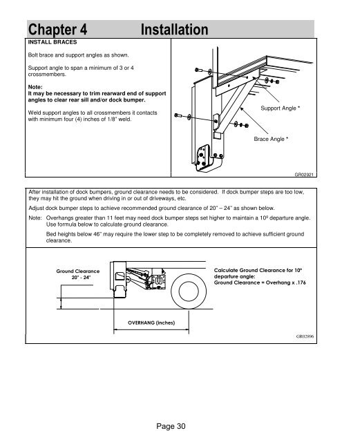
Chapter 4INSTALL BRACES<strong>Installation</strong>Bolt brace and support angles as shown.Support angle to span a minimum of 3 or 4crossmembers.Note:It may be necessary to trim rearward end of supportangles to clear rear sill and/or dock bumper.Weld support angles to all crossmembers it contactswith minimum four (4) inches of 1/8” weld.Support Angle *Brace Angle *GR02921After installation of dock bumpers, ground clearance needs to be considered. If dock bumper steps are too low,they may hit the ground when driving in or out of driveways, etc.Adjust dock bumper steps to achieve recommended ground clearance of 20” – 24” as shown below.Note: Overhangs greater than 11 feet may need dock bumper steps set higher to maintain a 10º departure angle.Use formula below to calculate ground clearance.Bed heights below 46” may require the lower step to be completely removed to achieve sufficient groundclearance.Ground Clearance20" - 24"Calculate Ground Clearance for 10ºdeparture angle:Ground Clearance = Overhang x .176OVERHANG (inches)GR02896Page <strong>30</strong>