BZ-33, 44 Series - Waltco
BZ-33, 44 Series - Waltco
BZ-33, 44 Series - Waltco

You also want an ePaper? Increase the reach of your titles
YUMPU automatically turns print PDFs into web optimized ePapers that Google loves.
www.waltco.com Phone: 800.411.5685<br />
parts@waltco.com Fax: 800.411.5684<br />
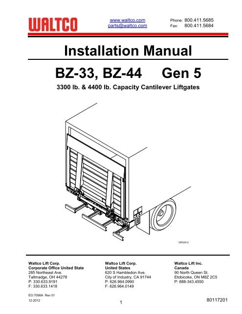
Installation Manual<br />
<strong>BZ</strong>-<strong>33</strong>, <strong>BZ</strong>-<strong>44</strong> Gen 5<br />
<strong>33</strong>00 lb. & <strong>44</strong>00 lb. Capacity Cantilever Liftgates<br />
GR02912<br />
<strong>Waltco</strong> Lift Corp. <strong>Waltco</strong> Lift Corp. <strong>Waltco</strong> Lift Inc.<br />
Corporate Office United State United States Canada<br />
285 Northeast Ave. 620 S Hambledon Ave. 90 North Queen St.<br />
Tallmadge, OH <strong>44</strong>278 City of Industry, CA 917<strong>44</strong> Etobicoke, ON M8Z 2C5<br />
P: <strong>33</strong>0.6<strong>33</strong>.9191 P: 626.964.0990 P: 888-343.4550<br />
F: <strong>33</strong>0.6<strong>33</strong>.1418 F: 626.964.0149<br />
EO:7006A Rev 01<br />
12-2012 80117201<br />
1
Table of Contents<br />
Improper installation of this liftgate could result in severe personal injury or<br />
death.<br />
Read and understand the contents of these instructions before proceeding.<br />
When installed, this liftgate must not alter or prevent vehicle compliance to any<br />
existing state or federal standards.<br />
Each chassis manufacturer’s recommendations should be consulted for<br />
compliance.<br />
Introduction ........................................................................................................................ 3<br />
Safety Information .............................................................................................................. 4<br />
Liftgate Terminology .......................................................................................................... 6<br />
Basic Mounting Requirements ........................................................................................... 8<br />
Liftgate Installation ........................................................................................................... 10<br />
Placement of Decals ........................................................................................................ 37<br />
Lubrication Instructions .................................................................................................... 41<br />
Final Inspection ................................................................................................................ 42<br />
Optional Kit Instructions:<br />
Aux Battery Kit (Truck) ..................................................................................................... 43<br />
Kit #80001066<br />
Aux Battery Kit (Trailer)<br />
Kit #80001069<br />
Full Door Seal Kit ............................................................................................................. 48<br />
Kit #80000573<br />
Flip-Up Door Installation .................................................................................................. 53<br />
(24” x 89”) Kit #14260011<br />
(30” x 89”) Kit #14260021<br />
(36” x 89”) Kit #14260031<br />
(24” x 95”) Kit #14260012<br />
(30” x 95”) Kit #14260022<br />
(36” x 95”) Kit #14260032<br />
How to Order Parts .......................................................................................................... 66<br />
2
Introduction<br />
If anyone observes improper installation, improper operation, or damage, they should immediately<br />
contact a qualified person for assistance and correction. We strongly urge anyone that has any<br />
questions or doubts as to the installation, condition, use, operation, maintenance or repair of the liftgate<br />
to contact us at <strong>Waltco</strong> where we have qualified personnel that will be happy to assist you. Telephone<br />
numbers and addresses of these locations are listed in the Owner’s Manual and Installation<br />
Instructions.<br />
INSTALLATION<br />
<strong>Waltco</strong> liftgates should only be installed by those with sufficient basic skills to understand the<br />
installation and operation of the liftgate, along with the equipment on which the liftgate is being<br />
installed. <strong>Waltco</strong>’s installation instructions are not intended to give rationale for all the instructions that<br />
are given; however, it is the intent of these instructions to give the installer both the operations and<br />
what we believe to be the most desirable sequence of implementing these operations. These<br />
instructions can in no way expand into an area where they will replace a qualified person, or clear<br />
thinking and a basic knowledge that must be possessed by the installer.<br />
It has been our experience that a knowledgeable journeyman following these instructions and<br />
observing the operation of the liftgate will have a sufficient comprehension of the liftgate to enable this<br />
person to troubleshoot and correct all normal problems that may be encountered.<br />
Failure to follow the installation instructions, adjustments and mounting dimensions may result in<br />
improper and unsafe operation of the liftgate. Unauthorized alterations of the liftgate can cause an<br />
undesirable and dangerous condition.<br />
OWNER’S MANUAL<br />
The <strong>Waltco</strong> Owner’s Manual is intended to act as a guide for operation and routine maintenance but<br />
is no way intended to encourage usage or repair of the liftgate by those who are not qualified to do so.<br />
The contents of the owner’s manual include, but are not limited to general operation instructions,<br />
routine lubrication, parts lists, and an outline of things that should be checked but may not be obvious<br />
to those not technically qualified. This manual assumes the liftgate is properly installed, undamaged<br />
and operates correctly. Improper installation, improper operation, or damage should be immediately<br />
corrected by a qualified person.<br />
INSPECTION<br />
As part of the regular inspection of a liftgate and after damage or suspicion of an overload, inspect<br />
for wear or structural damage and make necessary repairs or replacements. Check all structural<br />
components and their attachment to the liftgate for cracked welds, loose fasteners, wear and part<br />
deformation. Check cylinder and hose for leaks. Inspections and repairs should be made by a qualified<br />
mechanic.<br />
REPLACEMENT PARTS<br />
Use only <strong>Waltco</strong> original equipment replacement parts. Components of other liftgate manufacturers<br />
may outwardly appear to be the same but are not interchangeable with <strong>Waltco</strong> products. <strong>Waltco</strong><br />
components are specifically designed for safety requirements, reliability and compatibility with our<br />
products. Refer to your <strong>Waltco</strong> parts manual when ordering parts. NOTE: When ordering, give model<br />
and serial number of liftgate.<br />
DECALS<br />
It is important that every vehicle that has a WALTCO Liftgate have legible DECALS clearly posted on<br />
the vehicle and an OWNER’S MANUAL in the vehicle at all times as a guide for proper operation and<br />
maintenance.<br />
Additional DECALS and OWNER’S MANUALS can be obtained from WALTCO LIFT CORP.<br />
3
Chapter 1<br />
Safety Information<br />
WARNING<br />
Read, understand, and follow all of the warning listed below.<br />
Failure to follow these warning could result in severe personal injury or death.<br />
<br />
<br />
<br />
<br />
<br />
<br />
<br />
<br />
<br />
<br />
<br />
<br />
<br />
<br />
<br />
<br />
<br />
<br />
<br />
<br />
<br />
<br />
<br />
<br />
<br />
Read and understand the Owner’s Manual, all decals and warning on liftgate before operating liftgate.<br />
Do not operate liftgate without a thorough knowledge and understanding of the operation of the liftgate.<br />
Liftgate hazards can result in crushing or falling.<br />
This liftgate is designed for loading and unloading of cargo. If personnel are required to ride liftgate, observe<br />
and familiarize yourself with the liftgate operation, decals and manuals. Ensure stable footing at all times.<br />
Do not ride liftgate with unstable loads.<br />
Wheeled loads must be properly retained from rolling.<br />
Tall, high center of gravity loads must be retained from falling over.<br />
Never overload liftgate:<br />
Load platform as close to the vehicle, and towards the middle of the platform as possible. Refer to owner’s<br />
manual and capacity decal of liftgate for maximum load and load placement.<br />
Keep hands and feet clear of all potential pinch points.<br />
Never use liftgate if it makes any unusual noise, has unusual vibration, raises or lowers unevenly, or fails to<br />
operate smoothly.<br />
Never use liftgate if it shows any signs of structural damage such as cracked welds, bent or distorted<br />
members.<br />
Do not attempt any repairs unless you are qualified to do so. Care should be taken when work is performed<br />
on a disabled liftgate located near moving traffic. When possible the vehicle should be moved away from<br />
traffic areas for repair. Precautionary measures should be taken to ensure personal safety including those<br />
recommended in Federal Motor Vehicle Safety Standards 571.125.<br />
When welding to liftgate, or liftgate components, take all necessary safety precautions, including using<br />
respiratory protection and other pertinent personal protective gear when welding harmful materials.<br />
All protective covers, guards, and safety devices must be in place and access doors closed before operating<br />
liftgate.<br />
Do not allow anyone to stand in, or near area, in which Platform will open and close before opening or closing<br />
Platform.<br />
Do not allow anyone to stand near the Platform where a falling load could land on them.<br />
Platform is always to be properly stored and secured for transit. See the Owner’s Manual for details.<br />
Take care to retain cargo during transit for liftgate Platforms which function as the tailgate or door of the cargo<br />
area. Small objects can fall through the space between the vehicle and the folded Platform.<br />
A Lock-Out device or Shut-Off Switch should always be used to prevent unauthorized use of liftgate.<br />
For liftgates with Runners, never use liftgate if Runners do not travel freely and smoothly.<br />
For liftgates with Roller Lifting Chain, the Chain should be replaced every (5) five years or 15,000 cycles,<br />
whichever comes first. Replace only with <strong>Waltco</strong> approved Roller Chain.<br />
Never transfer loads which exceed lifting capacity on or over any part of the Platform unless the liftgate is<br />
equipped with a special reinforced Platform and Platform Support Bars for use when the Platform is used as<br />
loading ramp (dock board). Refer to the “Using Platform as a loading ramp” Chapter in the Operation<br />
Instructions of the <strong>BZ</strong>/RZ series Owner’s Manual.<br />
For liftgates equipped with Trailer Hitches, never exceed the rated capacity of the hitch. Do not exceed the<br />
vehicle’s weight rating. Refer to the vehicle’s Owner’s Manual.<br />
Vehicle must comply with all state and federal standards.<br />
Follow the “Maintenance Guide” chapter in the Owner’s Manual.<br />
4
Liftgates with Tilt Function<br />
Proper use of the Control Switches is of extreme importance.<br />
Improper use of Tilt Switch could cause load to fall from the Platform or damage the liftgate.<br />
Platform should be in a generally horizontal position when raising or lowering with a load.<br />
In any tilt position, the Platform may vary from level while raising or lowering the Platform.<br />
Liftgates equipped with spring operated Cam Closer<br />
Replace Cam Release Spring every five (5) years or 15,000 cycles, whichever comes first.<br />
RGL-<strong>Series</strong> Liftgates<br />
Make certain Platform Brake mechanisms are operating properly.<br />
The Runners are always to remain powered up against the Up-stops Pins when in transit.<br />
Inspect Cables every three (3) months or 750 cycles, whichever comes first. Cables must be replaced if they<br />
show signs of wear, distortion, kinking or if any broken wires are visible<br />
Replace cables every five (5) years or 10,000 cycles, whichever comes first.<br />
This is the safety alert symbol. This manual uses this symbol to alert you to potential personal injury<br />
hazards.<br />
Obey all safety messages that follow this symbol to avoid personal injury or death.<br />
SIGNAL WORDS<br />
WARNING<br />
Indicates a potentially hazardous situation, which if not<br />
avoided, could result in death or serious injury.<br />
Black letters on an orange background<br />
CAUTION<br />
Indicates a potentially hazardous situation, which if not<br />
avoided, may result in minor or moderate injury. May<br />
also be used to alert against unsafe practices.<br />
Black letters on a yellow background.<br />
NOTICE<br />
Indicates a potentially hazardous situation, which if not<br />
avoided, may result in property damage.<br />
WARNING<br />
CAUTION<br />
NOTICE<br />
5
Chapter 2<br />
Liftgate Terminology<br />
1. Platform<br />
2. Mount Tube<br />
3. Pump and Motor Tray<br />
4. Lift Arm<br />
15<br />
16<br />
5. Bumper<br />
6. Lift Cylinder<br />
7. Tilt Cylinder<br />
1<br />
8. Upper Lift Arm Pin<br />
9. Lower Lift Arm Pin<br />
14<br />
10. Upper Lift Cylinder Pin<br />
17<br />
11. Lower Lift Cylinder Pin<br />
17<br />
12. Upper Tilt Cylinder Pin<br />
14<br />
13. Lower Tilt Cylinder Pin<br />
14. Marker Lights<br />
15. Sill Extension<br />
16. Mount Plates<br />
17. Cart stop (optional)<br />
GR00828<br />
14<br />
14<br />
8<br />
5<br />
4<br />
12<br />
7<br />
5<br />
3<br />
10<br />
7<br />
5<br />
6<br />
9<br />
2<br />
6<br />
13<br />
11<br />
GR00829<br />
6
Chapter 2<br />
Liftgate Terminology<br />
EXPLANATION OF SPECIFICATION TAG<br />
MODEL NAME DESCRIPTION CAPACITY<br />
<strong>BZ</strong><strong>33</strong> G5 LEVEL LIFT <strong>33</strong>00 LBS.<br />
<strong>BZ</strong><strong>44</strong> G5 LEVEL LIFT <strong>44</strong>00 LBS.<br />
MODEL NAME<br />
RATED CAPACITY<br />
Based on an evenly<br />
distributed load on the<br />
platform flat surface<br />
SERIAL NUMBER<br />
of Liftgate. To be used<br />
when ordering parts or<br />
when contacting <strong>Waltco</strong><br />
for service or warranty.<br />
LOCATION OF SPECIFICATION TAG<br />
Can be found on driver’s side, end of mount tube.<br />
Usually found<br />
on this end<br />
DATE OF<br />
MANUFACTURE<br />
MONTH/YEAR<br />
On some older liftgates<br />
may be located here<br />
GR00053<br />
Mount Tube<br />
GR02226<br />
7
Chapter 3 Basic Mounting Requirements<br />
DETERMINE MOUNTING DIMENSIONS<br />
Determine bed height. Measure from top of vehicle floor<br />
down to ground.<br />
Verify which length arms liftgate has.<br />
1-3/4”<br />
MOUNT TUBE<br />
CLEARANCE<br />
FLOOR LEVEL<br />
SILL DEPTH<br />
NOTE: All dimensions when vehicle unloaded on<br />
horizontal surface.<br />
“A”- DIMENSION<br />
IMPORTANT! Do not exceed given A- dimension or<br />
max bed height. This can cause damage to liftgate and<br />
improper operation of liftgate.<br />
GROUND<br />
GROUND<br />
CLEARANCE<br />
BED<br />
HEIGHT<br />
Additional mounting configurations and dimensions may<br />
be available by contacting the <strong>Waltco</strong> Engineering<br />
Department.<br />
Note! Always use the smallest A-<br />
dimension possible.<br />
GR00494<br />
FRAME WIDTH<br />
Liftgates can be mounted to trucks and trailers with max<br />
frame width 45- 1/2”.<br />
45-1/2” MAX<br />
Additional mounting configurations and dimensions may<br />
be available by contacting the <strong>Waltco</strong> Engineering<br />
Department.<br />
77- 3/4”<br />
GR00655<br />
MOUNTING BRACKETS<br />
13-1/4<br />
Mounting brackets height may need to be trimmed in<br />
order to achieve desired A- dimension.<br />
IMPORTANT! Do not modify mounting bracket bolts,<br />
nuts or mounting surfaces that are in contact with mount<br />
tube.<br />
8-1/4<br />
1-1/8<br />
7 15-3/16<br />
2-7/16<br />
3-1/4<br />
GR00495<br />
8
Chapter 3 Basic Mounting Requirements<br />
NOTE:<br />
Mount tube must be installed at least 1-5/8” below<br />
vehicle chassis to allow room for mounting brackets.<br />
1-5/8”<br />
GR00496<br />
INSTALLATION DIMENSIONS<br />
<strong>BZ</strong>-<strong>33</strong>/<strong>44</strong> Short arm, 29-1/2" Optional<br />
14.0 41 - 42.5 14 - 16 5.5 <strong>33</strong><br />
16.5 42.5 - 45 14 - 16 6 31.5<br />
18.5 <strong>44</strong> - 47 14 - 16 6.5 30<br />
20.5 47 - 49 14 - 16 7 28.5<br />
22.5 49 - 51 14 - 16 8 26.5<br />
24 51 - 52.5 14 - 16 8.5 24.5<br />
<strong>BZ</strong>-<strong>33</strong>/<strong>44</strong> Long arm, 34-1/4" Standard<br />
"A" Dimension Bed Height Ground clearance Maximum sill depth Mount tube clearance<br />
17 45.5 - 49 17 - 19 6 37<br />
19 49 - 51 17 - 19 6.25 35.5<br />
21 51 - 53 17 - 19 6.5 34<br />
23 53 - 55 17 - 19 7 32.5<br />
25 55 - 57 17 - 19 8 31<br />
27 57 - 59 17 - 19 8.5 28.5<br />
28 59 - 60 17 - 19 9 27<br />
Note! Always use the smallest A- dimension possible to maximize ground clearance.<br />
9
Chapter 4<br />
Liftgate Installation<br />
PREPARATION OF BODY<br />
Remove all obstructions that will interfere with liftgate<br />
operation.<br />
Dock bumpers<br />
Trailer hitches<br />
Other projections<br />
GR00511<br />
NOTCH REAR SILL<br />
Mark a witness line at center of rear sill. This line will be<br />
used for centering the liftgate later.<br />
If rear sill is deeper than the “Max Sill Depth”, as<br />
indicated in the Mounting Requirements, notch as<br />
shown.<br />
GR00497<br />
REINFORCE SILL NOTCH<br />
Use 3/16” or 1/4” x 2” steel bar.<br />
Form bar and weld in place.<br />
GR00056<br />
REINFORCE REAR SILL AREA<br />
If necessary extend chassis frame back to rear sill.<br />
Add bar or angle to cap off frame and tie it in with rear<br />
sill.<br />
Add a tie strap on the side of the chassis frame to tie it<br />
together with the body long member.<br />
GR00057<br />
10
Chapter 4<br />
Liftgate Installation<br />
CONSTRUCT MOUNTING JIG<br />
Cut a length of 3” angle, or similar material, approx. 70”<br />
long.<br />
Make two (2) plates with 1-3/16” dia. holes as shown.<br />
60-1/4"<br />
BETWEEN PLATES<br />
3" CHANNEL<br />
OR SIMILAR<br />
MARK CENTERLINE<br />
BETWEEN PLATES<br />
4<br />
1/4<br />
1/4<br />
1 3/8<br />
5 3/4<br />
n 1-3/16"<br />
3 1/8<br />
GR00498<br />
Locate and tack-weld the mounting jig to rear sill of<br />
body.<br />
Align the centerline marks of the jig with mark on sill.<br />
Verify the 1-3/8” and 3-1/8” dimensions.<br />
Note: For vehicles with swing doors, refer to section in<br />
back of manual “For Vehicles with Swing Doors”.<br />
GR00499<br />
11
Chapter 4<br />
Liftgate Installation<br />
MOUNT LIFTGATE TO MOUNTING JIG<br />
Disconnect all four (4) cylinders from the lift arms.<br />
Remove the temporary shipping pins from the tilt<br />
cylinders and lift arms.<br />
Remove the lock nuts and pins from the lift cylinders<br />
and lift arms.<br />
Note: The outer two cylinders are the tilt cylinders.<br />
Do not remove any pins from mount frame.<br />
GR00060<br />
Check that lift arm assembly pivots freely on pivot pins<br />
in mount frame.<br />
If necessary, loosen nuts on pivot pins indicated.<br />
GR00061<br />
Position liftgate mount frame on a floor jack or other<br />
type of lifting device.<br />
Rotate lift arms up to the mounting jig.<br />
Temporarily secure lift arms to mounting jig with long<br />
bolts and nuts supplied with liftgate or platform.<br />
Other means may be used to support<br />
Mount Frame in position. ALWAYS verify<br />
the safety of your supporting method<br />
before proceeding.<br />
GR00062<br />
12
Chapter 4<br />
Liftgate Installation<br />
Jack mount frame up to the proper “A” Dimension.<br />
Refer to the Mounting Requirements in this manual.<br />
Note: Use the smallest “A” Dimension per the chart, this<br />
insures the greatest ground clearance.<br />
Important: Top of mount tube is not to contact the<br />
vehicle chassis frame.<br />
GR00063<br />
Position mount plates over mount tube, and up against<br />
vehicle chassis frame.<br />
Open end of mount plates must face front of vehicle.<br />
Rotate liftgate and mount plate so plate is 90° degrees<br />
to chassis frame.<br />
Drill ½” holes, centered in slots, through chassis frame.<br />
MOUNT PLATE<br />
CHASSIS<br />
FRAME<br />
DRILL 1/2"<br />
HOLES<br />
90°<br />
TRIM MOUNT PLATE<br />
IF NECESSARY<br />
Note: In some installations it may be necessary to trim<br />
off top of mount plates to clear body cross members.<br />
GR00064<br />
Bolt mount plates to chassis frame and install endplates<br />
onto mount plates.<br />
Using 1/2” bolts and square washers, bolt mount plates<br />
to vehicle chassis frame.<br />
Install endplates as shown with provided nuts and<br />
washers and torque to 85 ft. lbs.<br />
Note: Do not install any more bolts or weld mount plates<br />
to chassis frame at this time.<br />
MOUNT PLATES BOLTED<br />
TO CHASSIS FRAME<br />
INSTALL ENDPLATE<br />
AS SHOWN<br />
GR00065<br />
13
Chapter 4<br />
Liftgate Installation<br />
Re-attach lift cylinders to lift arms.<br />
Unbolt lift arms from mounting jig, and lower arms to<br />
ground.<br />
Reinstall lift cylinder pins and locking nuts.<br />
Remove mounting jig from rear sill.<br />
LIFT<br />
CYLINDER<br />
PIN<br />
REMOVE MOUNTING JIG<br />
LIFT CYLINDER<br />
GR00066<br />
14
Chapter 4<br />
Liftgate Installation<br />
15
Chapter 4<br />
Liftgate Installation<br />
Electric and Hydraulic Diagram<br />
16
Chapter 4<br />
Liftgate Installation<br />
Electric and Hydraulic Diagram (with Auto-tilt)<br />
17
Chapter 4<br />
Liftgate Installation<br />
No. Color<br />
1 Yellow / Green<br />
2 Blue<br />
3 Brown<br />
4 Black<br />
5 Green<br />
6 White<br />
7 Red<br />
8 Yellow<br />
9 Grey<br />
10 Orange<br />
CAB SWITCH INSTALL (For Trucks)<br />
<strong>Waltco</strong> recommends that a Cab Switch be used as a<br />
safety lockout device to prevent unauthorized use of the<br />
liftgate.<br />
Route Cab Switch (16GA orange and black) wire from<br />
control unit to the Truck Cab.<br />
Mount Cab Switch and Warning light into dash of truck.<br />
Connect black wire to Cab Switch.<br />
Connect orange wire to Warning Light.<br />
Route wires from the Cab Switch and the warning light<br />
to the 8 amp circuit fuse and to battery. DO NOT<br />
connect to battery at this time.<br />
Route a wire from the Gold colored terminal on the Cab<br />
Switch to ground.<br />
IMPORTANT: All wires and cables are to be protected<br />
from sharp edges, exhaust stream, being pinched or<br />
abraded by liftgate mechanism, cargo, etc.<br />
Optional wiring with no Cab Switch<br />
18
Chapter 4<br />
Liftgate Installation<br />
SHUT-OFF SWITCH INSTALL (For Trailers)<br />
<strong>Waltco</strong> recommends that a Shut-Off Switch be used as<br />
a safety lockout device to prevent unauthorized use of<br />
the liftgate.<br />
Route cab switch (16GA orange and black) wire from<br />
control unit to the shut-off switch.<br />
Connect black wire to shut-off switch.<br />
Orange wire is not used.<br />
Route a wire from the shut-off switch to 10 amp circuit<br />
fuse and to battery. DO NOT connect to battery at this<br />
time.<br />
All wires and cables are to be protected<br />
from sharp edges, exhaust stream,<br />
being pinched or abraded by liftgate<br />
mechanism, cargo, etc.<br />
INSTALLATION OF COMPRESSION TERMINALS<br />
Cut power cable (red) and ground cable (black) to length<br />
and install compression terminals.<br />
Strip 7/8” to 1” of insulation from end of cable.<br />
Slide heat shrinkable tubing onto cable.<br />
Insert bare wire into compression nut until it seats.<br />
Note: Copper wire should be flush with, or slightly<br />
past, the nut.<br />
Grip nut with wrench and turn terminal until nut seats.<br />
Heat shrinkable tubing<br />
Before installation<br />
7/8” to 1”<br />
Position heat shrinkable tubing over terminal and end of<br />
cable.<br />
Shrink tubing using electric heat gun or torch.<br />
Note: To reduce chance of damaging tube and<br />
cable, a heat gun is recommended.<br />
Apply sufficient heat to produce thin bead of sealant all<br />
around tube edges.<br />
Beads of sealant<br />
Heat shrinkable tubing<br />
GR00299/ GR00300<br />
GR00301<br />
19
Chapter 4<br />
INSTALL TERMINALS TO BATTERY<br />
Connect red 2GA cable to red quick connector behind<br />
main frame.<br />
Route positive battery cable from lift unit to battery box.<br />
Connect the end of the battery cable from the liftgate to<br />
the circuit breaker as shown.<br />
Apply a generous amount of Dielectric Grease to all<br />
Positive (Hot) Battery terminals and Circuit Breaker<br />
terminals.<br />
Secure all battery cables to the vehicle frame with the<br />
cable ties provided.<br />
Liftgate Installation<br />
Copper terminal Link<br />
(10099500) connected<br />
direct to Battery Post<br />
and Circuit Breaker<br />
Positive (Red)<br />
Battery Cable from<br />
liftgate<br />
Ground (Black)<br />
Cable from liftgate<br />
150 Amp<br />
Circuit<br />
Breaker<br />
IMPORTANT! Original equipment ground cable<br />
furnished on vehicle should be at least a number 2 Ga.<br />
An auxiliary ground cable should be added between the<br />
engine block and the vehicle frame if engine is not<br />
adequately grounded. When there are two or more<br />
batteries in the installation, all cables connecting the<br />
batteries together must be 2 Ga. or heavier. This<br />
includes all original equipment batteries on this vehicle.<br />
Protect wires from any sharp edges or<br />
holes that may abrade insulated<br />
covering of wires.<br />
Secure battery cable so it does not<br />
come near, or in contact with, other<br />
vehicle wiring, fuel lines, brake lines,<br />
air hoses, exhaust system, etc.<br />
Apply a generous<br />
amount of Dielectric<br />
Grease to all Battery<br />
terminals and Circuit<br />
Breaker terminals.<br />
NOTE:<br />
Circuit Breaker is to rest<br />
solidly on the battery to<br />
prevent vibration during<br />
transit.<br />
Battery Box<br />
20
Chapter 4<br />
REMOVE TRANSPORT PLUG<br />
Liftgate Installation<br />
Replace transport plug from oil tank with breather plug.<br />
Check oil level, oil level should be ½” below top of oil<br />
tank.<br />
Add oil if needed.<br />
Do not over fill.<br />
BREATHER PLUG<br />
GR00830<br />
Recommended Fluids<br />
Fill reservoir<br />
Temperature Range Acceptable Fluids • Fill with recommended fluid or equivalent.<br />
0° to 120° F <strong>Waltco</strong> Biodegradable • Fill the reservoir to within 1/2” from the top.<br />
Liftlube TM part #85803860 • Fluids are available from the <strong>Waltco</strong> parts<br />
Shell Tellus S2 V 32<br />
Dept. 1-800-411-5685 www.waltco.com<br />
Chevron AW32<br />
-20° to 90° F <strong>Waltco</strong> Biodegradable<br />
LiftLube Arctic part<br />
#85803866<br />
NOTE:<br />
Do not use the following fluids:<br />
Shell Tellus S2 V 15<br />
Mobil DTE 13<br />
MIL – H - 5606<br />
Brake Fluid<br />
Power steering fluid<br />
Automatic Transmission Fluid (ATF)<br />
A good quality SAE 10W motor oil may also be used in<br />
temperatures above 32° F.<br />
OPERATING GATE WITHOUT BATTERIES<br />
If the liftgate needs to be operated before the batteries<br />
are installed, temporary battery and battery charger can<br />
be used.<br />
BATTERY<br />
CHARGER<br />
Note! Never operate liftgate only with battery charger,<br />
this can cause damage to electrical parts.<br />
LIFTGATE<br />
BATTERY<br />
GR01091<br />
21
Chapter 4<br />
Liftgate Installation<br />
22
Chapter 4<br />
Liftgate Installation<br />
Function schematic<br />
(also referring to corresponding electrical and hydraulic diag.)<br />
<strong>BZ</strong>-<strong>33</strong>/<strong>44</strong> (1) &<br />
<strong>BZ</strong>-<strong>33</strong>/<strong>44</strong> with Auto-tilt (2)<br />
23
Chapter 4<br />
Liftgate Installation<br />
24
Chapter 4<br />
Liftgate Installation<br />
INSTALL REAR SILL EXTENSION<br />
Cut extension so it will extend to within ½” of each side<br />
to vehicle body.<br />
Position and weld extension, centered on door opening.<br />
Note: If the full door seal kit, or flip-up door option are to<br />
be used, they will use a different type of sill extension.<br />
Note: For vehicles with swing doors, refer to the section<br />
in the back of this chapter “Swing door application”.<br />
GR00086<br />
POSITIONING OF PLATFORM<br />
Using the raise switch, raise lift arms up off the ground<br />
as shown.<br />
Lift Platform Using an Over-Head Crane or Forklift as<br />
shown.<br />
Other means may be used to support the<br />
platform in position. ALWAYS verify the<br />
safety of your supporting method before<br />
proceeding.<br />
GR00087<br />
INSTALLATION OF LIFT ARMS<br />
Align the Lift Arms with the upper holes in the Platform<br />
Hinges.<br />
Pin the Lift Arms to the Platform Hinges as shown.<br />
Secure pins with lock nuts.<br />
Platform hinge<br />
(inner plate)<br />
Platform hinge<br />
(outer plate)<br />
Platform hinge<br />
(middle plate)<br />
Pin tang to fully engage in<br />
hole of platform hinge<br />
(middle plate)<br />
GR01762<br />
25
Chapter 4<br />
Liftgate Installation<br />
INSTALLATION OF TILT CYLINDERS<br />
Manually Pivot the Tilt Cylinders into position.<br />
Extend or Retract the Tilt Cylinders as needed, to align<br />
rod eye with lower pivot holes in Platform Hinges, by<br />
using the Raise and Tilt or Lower and Tilt switches.<br />
Install Tilt Cylinder Pins, washers, support wheel and<br />
lock nuts as shown.<br />
Pin tang to fully<br />
engage in hinge<br />
(middle plate)<br />
Platform hinge<br />
(middle plate)<br />
GR01763<br />
ADJUSTMENT OF PLATFORM GAP<br />
Bring platform horizontal with bed of vehicle. Be careful<br />
not to damage rear sill extension.<br />
The platform and rear sill must have a gap between 1-<br />
3/4” and 1-15/16”.<br />
Determine how much and in which direction the platform<br />
must be moved.<br />
Lower the platform to the ground.<br />
1-3/4 - 1-15/16<br />
GR00837<br />
Loosen mount bracket bolts.<br />
Move mount frame as necessary.<br />
Torque bolts to 85 ft. lbs.<br />
Raise Platform horizontal with bed of vehicle and tilt up<br />
to transport position. Check to see that the gap<br />
requirements have been met.<br />
TORQUE TO 85 FT. LBS<br />
AFTER ACHIEVING<br />
PROPER GAP<br />
SLIDE TO ACHIEVE<br />
PROPER PLATFORM<br />
GAP OF 1/8"-1/4"<br />
FINAL INSTALL OF MOUNT BRACKETS<br />
(BOLT METHOD)<br />
Note: If planning on welding mount brackets to chassis<br />
frame, skip to the next step.<br />
Lower platform to the ground.<br />
Use mount brackets as a template and drill the<br />
remaining holes in the chassis frame.<br />
Install the remaining bolts and torque to 85 ft. lbs.<br />
DRILL 1/2" HOLES<br />
AND INSTALL<br />
REMAINING BOLTS,<br />
NUTS, AND WASHERS<br />
GR00091<br />
GR00092<br />
26
Chapter 4<br />
Liftgate Installation<br />
WELDING, CUTTING AND GRINDING<br />
Before doing any metal work:<br />
Pull pump unit out from main frame and cover with<br />
non flammable material.<br />
Cover piston rods with non flammable material.<br />
PULL PUMP<br />
UNIT OUT<br />
Welding, torching or grinding can damage<br />
cylinders, hoses or electrical system.<br />
COVER<br />
GR00508<br />
WELDING<br />
Welding machines ground point must connected as<br />
close to welding point as possible.<br />
Do not allow ground current go through pivot pins,<br />
bearings, cables or hydraulic hoses.<br />
Welding current can melt cables or burst<br />
hoses causing personal injury.<br />
DO NOT<br />
GROUND<br />
WELDING<br />
MACHINE TO<br />
CYLINDERS<br />
GR00508<br />
PAINTING<br />
IMPORTANT! Do not paint the cylinder piston rods!<br />
Any paint applied to piston rods will eventually effect the<br />
operation of liftgate by contaminating the entire<br />
hydraulic system, causing blockages in valves, pump,<br />
filter, cylinders, and hoses.<br />
DO NOT ALLOW<br />
ANY PAINT ON<br />
PISTON RODS!<br />
GR00508<br />
FINAL INSTALL OF MOUNT BRACKETS<br />
(WELD METHOD)<br />
Lower platform to the ground.<br />
Weld mount brackets to chassis frame 100% as shown.<br />
GR00093<br />
27
Chapter 4<br />
Liftgate Installation<br />
INSTALL UP STOPS<br />
Liftarms movement up must be limited mechanically.<br />
Rear sill is not strong enough to withstand forces from<br />
liftgate.<br />
Use 2” x 2” x .25 tube (or similar) to limit up movement<br />
of lift arm as shown.<br />
Material for up stops is not provided.<br />
Raise platform to bed height.<br />
Position up stops on top of lift arms and against<br />
vehicle chassis frame.<br />
Tack weld up stops to chassis frame and lower<br />
platform to the ground.<br />
Verify that hydraulic hoses or wires will not<br />
get crushed between lift arms and upstops.<br />
GR01169<br />
Add support beam or gusset to up stop to prevent up<br />
stops bending.<br />
Material for this is not provided.<br />
IMPORTANT! Add support to up stops to prevent<br />
bending.<br />
GR01170<br />
Make sure that up stops will contact lift arms as shown<br />
on drawing.<br />
IMPORTANT! Up stop must contact lift arms as shown.<br />
GR00455<br />
28
Chapter 4<br />
Liftgate Installation<br />
HYDRAULIC AUTOMATIC TILT<br />
For units equipped with Auto-tilt, install the angle<br />
sensor. The angle sensor should be positioned on the<br />
lift arm as shown:<br />
GR02802<br />
CONSTRUCTION OF TILT CYLINDER<br />
1. Screw<br />
2. Adjustable collar<br />
3. Washer<br />
4. Lock screw (x3)<br />
5. Ring<br />
6. Ring’s Lock Screw<br />
Ring’s Lock Screw<br />
GR02803<br />
ADJUSTING TILT UP ANGLE<br />
Note: Do not adjust the tilt cylinders before they are<br />
installed onto the platform. Tilt cylinders are preadjusted<br />
at the factory.<br />
Note: Make sure<br />
the grease zerk<br />
Is facing upwards<br />
Position and install cylinder as shown:<br />
GR02813<br />
29
Chapter 4<br />
Liftgate Installation<br />
IMPORTANT!<br />
Tilt up the platform until it closes without tilting over<br />
90°. The tilt cylinders should be fully extended. If<br />
platform will tilt over 90° tilt cylinders must be adjusted<br />
in order to prevent damage of over tilting.<br />
Cylinder adjustments should be made when the<br />
cylinders are fully pressurized.<br />
GR02814<br />
Loosen rubber bellows and loosen (3) lock screws.<br />
Turn adjustable case counter-clockwise to decrease<br />
length of tilt cylinder or clockwise the increase length.<br />
*Adjust until the platform reaches top sill of truck<br />
(GR02814, detail A) Fine Adjust until platform fits tightly<br />
against top sill (GR02814, detail B)<br />
Always adjust left and right side equally.<br />
(“*” Only for trucks with ceiling and/or top sill)<br />
GR02815<br />
Tighten lock screws and measure the exposed cylinder<br />
threads; not to exceed more the 1-3/16”<br />
Lock screws torque is between 26.4 – <strong>44</strong>.4 ft/in<br />
Max 1-3/16”<br />
Do not adjust to expose more than 1-3/16”<br />
of threads.<br />
GR02828<br />
30
Chapter 4<br />
ADJUSTING TILT DOWN ANGLE<br />
Liftgate Installation<br />
Note: To obtain the correct tilt down function, it is<br />
necessary to follow the previous instructions which<br />
ensure a correct 90° tilt angle up against the truck’s<br />
body.<br />
Cycle the lift up until it reaches floor level.<br />
GR02829<br />
Loosen the cylinder ring’s lock screw (1). Screw the ring<br />
out in the direction of the platform (2)<br />
Tilt the platform a maximum of 10° below the horizontal<br />
as shown in Fig-GR02829<br />
1<br />
2<br />
GR02816<br />
Tighten the ring to the top of the cylinder (3) and then<br />
tighten the lock screw into the ring (4) after tilt down<br />
angle is established<br />
4<br />
3<br />
GR02817<br />
Reassemble the rubber bellows as shown to the<br />
following A dimensions:<br />
Liftgate Model:<br />
Short Arm<br />
A: (inches)<br />
7 <br />
± <br />
<br />
~ 3/8”<br />
Long Arm<br />
11 <br />
± <br />
<br />
Test all the functions of liftgate.<br />
Make sure that platform fits properly against top sill (if so<br />
equipped).<br />
GR02818<br />
31
Chapter 4<br />
Liftgate Installation<br />
PLATFORM RUBBER STOPS<br />
If the vehicle is not equipped with at least side seals,<br />
rubber stops for the platform must be installed on the<br />
corner post of the body at a height of 2/3’s the height of<br />
the closed liftgate platform on both corner posts<br />
PLATFORM<br />
Install rubber stops as shown and adjust tilt cylinders so<br />
that the platform firmly contacts the stops when fully<br />
closed.<br />
Space rubber stops out from corner post as may be<br />
required. Spacers not provided.<br />
RUBBER STOP<br />
GR01605<br />
FLAT BED APPLICATIONS<br />
On flat bed applications, vehicle must be equipped with<br />
corner posts.<br />
Make sure that the corners post are strong enough to<br />
support forces from platform.<br />
RUBBER STOP OR<br />
PIECE OF SEALING<br />
Install rubber stops as shown and adjust tilt cylinders so<br />
that the platform firmly contacts the stops when fully<br />
closed.<br />
Space rubber stops out from corner post as may be<br />
required. Spacers not provided.<br />
GR01606<br />
32
Chapter 4<br />
INSTALLATION OF 3-PIECE BUMPER<br />
Liftgate Installation<br />
Install (3) piece bumper as shown.<br />
NOTE: All (3) pieces need to be installed!<br />
Bumper bars have three height adjustment possibilities;<br />
all bumper bars must be installed to same height<br />
position.<br />
Every bumper bar must be secured with three bolts and<br />
lock nuts (supplied).<br />
GR02819 & GR00507<br />
SWING DOOR APPLICATION<br />
Platform must be spaced away from the vehicle such<br />
that when the liftgate is in the closed position it does not<br />
contact the door hardware.<br />
Note: Sill extension is not used with vehicles with swing<br />
doors.<br />
SPACE PLATFORM FROM<br />
DOOR HARDWARE<br />
SPACE OUT RUBBER STOP<br />
Note: Rubber stops for platform must be spaced out if<br />
bridge piece is used.<br />
GR00111<br />
<strong>33</strong>
Chapter 4<br />
Liftgate Installation<br />
BRIDGE FABRICATION<br />
A bridge may be fabricated approximately as shown to<br />
reduce the gap between the platform and sill in the<br />
previous step.<br />
The bridge must be notched for door hardware. It must<br />
also be wide enough and constructed such that its<br />
strength is not compromised by the notching.<br />
Note: Widening bridge further spaces platform away<br />
from vehicle.<br />
GR00112<br />
INSTALLING BRIDGE<br />
There must approximately 5/8” gap between platform<br />
and bridge to prevent interference.<br />
It is recommended to also leave approximately 1/2” gap<br />
between platform and rear sill to prevent interference.<br />
Note: It is recommended to clamp or tack weld to test<br />
position before final installation.<br />
5/8" 1/2"<br />
GR00838<br />
34
Chapter 4<br />
Liftgate Installation<br />
FINAL INSTALLATION OF BRIDGE<br />
Weld bridge to lift arms 100% as shown.<br />
BRIDGE<br />
3/16<br />
TYP<br />
LIFT ARM<br />
GR00114<br />
LOADING AREA<br />
Bridge will pivot over back of platform when lowered.<br />
Mark back of platform as a no loading area as<br />
necessary.<br />
BRIDGE<br />
GR00115<br />
OPERATION CHECK<br />
• Turn shut-off switch on (located in cab)<br />
• Always make certain area in which platform<br />
will open is clear<br />
• Push and hold tilt switch then lower switch<br />
to unfold platform<br />
RAISE<br />
TILT<br />
LOWER<br />
35
Chapter 4<br />
Liftgate Installation<br />
GR00106<br />
TO RAISE AND LOWER PLATFORM IN<br />
LOADING POSITION.<br />
• Push raise switch to raise platform<br />
Or<br />
• Push lower switch to lower platform<br />
GR00107<br />
TO TILT PLATFORM UP AND DOWN.<br />
• First push and hold tilt switch, then<br />
simultaneously push raise switch to tilt<br />
platform up.<br />
Or<br />
• First push and hold tilt switch, then<br />
simultaneously push lower switch to tilt<br />
platform down.<br />
GR00108<br />
TO FOLD PLATFORM TO CLOSED<br />
POSITION.<br />
• Make certain platform surface is clear of all<br />
objects.<br />
• Raise platform to bed level with raise<br />
switch.<br />
• Push and hold tilt switch then<br />
simultaneously push raise switch to close<br />
platform.<br />
• Turn shut-off switch off<br />
GR00110<br />
36
Chapter 5 Placement of Decals<br />
INSTALLATION OF CONTROL DECALS<br />
Install all decals listed below. Be certain they are<br />
installed in the proper location and are legible.<br />
All decals must be in place and legible or all<br />
warranties are void.<br />
Each of the following four (4) decals are to be positioned<br />
in a conspicuous place near the control switches as<br />
shown.<br />
80100850 – Safety Instruction Decal<br />
80101451 – Operation Decal<br />
80100828 – Important Decal<br />
80101370 – Hazard decal<br />
One (1) of the following three (2) decals is to be<br />
positioned in a conspicuous place near the control<br />
switches as shown.<br />
80101415 – <strong>BZ</strong>-<strong>33</strong> Capacity Decal<br />
80101416 – <strong>BZ</strong>-<strong>44</strong> Capacity Decal<br />
If your liftgate is equipped with dual<br />
controls, an additional Safety Instruction<br />
decal (80100850) is to be placed in a<br />
conspicuous place near the second set of<br />
controls.<br />
PLACE DECALS IN THIS AREA<br />
To maximize decal adhesion to surfaces:<br />
• Surface must be dry and clean<br />
• Firm pressure must be applied to decal<br />
• Minimum surface temperature 65º<br />
Heat gun may be used to heat surface<br />
GR02913<br />
INSTALLATION OF DRIVE-OVER WARNING DECAL<br />
The following decal is to be positioned in a conspicuous<br />
place near the control switches as shown.<br />
80100592 – Drive Over Decal<br />
If unit is equipped with drive over kit decal<br />
80101<strong>33</strong>0 must be used in place of decal<br />
80100592.<br />
GR02914<br />
37
Chapter 5 Placement of Decals<br />
INSTALLATION OF PLATFORM DECALS<br />
The following decals are to be placed on the underside<br />
of the platform and both sides of vehicle as shown.<br />
75089296 – Stand Clear Decal (4)<br />
STAND CLEAR<br />
DECALS HERE<br />
One (1) of the following three (2) decals is to be<br />
positioned in a conspicuous place on the bottom of the<br />
platform as shown<br />
80101415 – <strong>BZ</strong>-<strong>33</strong> Capacity Decal<br />
80101416 – <strong>BZ</strong>-<strong>44</strong> Capacity Decal<br />
CAPACITY DECAL HERE<br />
GR00511<br />
INSTALLATION OF SAFETY TAPE<br />
Tape (Z20290) is to be placed on the sides of platform<br />
so it is visible from the side and back of vehicle as<br />
shown.<br />
IMPORTANT! Safety<br />
tape must wrap<br />
around side of<br />
platform as shown.<br />
IMPORTANT! Safety tape must wrap around side of<br />
platform as shown.<br />
GR00511<br />
38
Chapter 5 Placement of Decals<br />
SAFETY TAPE AND FLAGS<br />
Tape (Z20290) is to be placed on the sides of platform<br />
so it is visible from the side.<br />
Locate corner flag mount brackets (Z20273), one on<br />
each side of platform and drill (3) holes per bracket into<br />
platform as shown. Use bracket as a template.<br />
Using slotted head screws provided (three per bracket),<br />
install flag mount brackets as shown.<br />
Slide flags (75089905) into mount brackets and crimp<br />
ends of each bracket to prevent flags from sliding out.<br />
Tape<br />
9”<br />
9” 9”<br />
Flag<br />
Flag mount<br />
bracket<br />
GR00043 & GR01761<br />
SHUT-OFF DECAL<br />
The following decal is to be placed next to the liftgate<br />
shut-off switch as shown.<br />
75089267 – Liftgate Shut-Off Decal<br />
PLACE<br />
DECAL AS<br />
SHOWN<br />
GR00121<br />
39
Chapter 5 Placement of Decals<br />
CIRCUIT BREAKER DECAL<br />
The following decal is to be placed next to the liftgate<br />
circuit breaker as shown.<br />
PLACE DECAL<br />
IN THIS AREA<br />
80100829 – Circuit Breaker Decal<br />
GR00122<br />
40
Chapter 6<br />
Lubrication<br />
LUBRICATION INSTRUCTIONS<br />
12 grease fittings should be lubricated with a grease gun per the lubrication schedule below.<br />
Note: All fittings should be greased with the platform in the stored position.<br />
SUGGESTED MINIMUM LUBRICATION SCHEDULE (IN DAYS)<br />
Monthly Cycles Light Duty Med. Duty Heavy Duty<br />
250 Or Less 45 30 21<br />
250-350 30 21 14<br />
350-450 21 14 7<br />
More Than 450<br />
Contact Factory for Instructions<br />
Note: If unsure of duty or cycles always lubricate more frequently.<br />
1. Tilt cylinder, lower pin<br />
2. Lift cylinder, lower pin<br />
3. Lift arm, lower pin<br />
4. Tilt cylinder, upper pin<br />
5. Lift cylinder, upper pin<br />
6. Lift arm, upper pin<br />
4<br />
6<br />
5<br />
3<br />
2<br />
1<br />
GR00508<br />
41
Chapter 7<br />
Final Inspection List<br />
IMPORTANT<br />
All of the following items are to be checked and verified before installation is complete.<br />
A. All welds are properly done.<br />
B. All bolts, nuts, and screws are tight and torqued to the proper specification.<br />
C. Control boxes and shut off switch function properly.<br />
D. All phases of the liftgate’s operation work properly.<br />
E. Platform raises level to the truck bed and the gap between the platform and sill<br />
extension is the correct distance.<br />
F. All decals are accounted for and legible.<br />
G. Lights are installed and operate properly.<br />
H. Vehicle meets all state and federal standards.<br />
I. Owner’s Manual is in the vehicle.<br />
J. Pump reservoir is full of oil.<br />
K. All grease fittings are lubricated.<br />
L. All hydraulic connections are tight.<br />
M. Up stops, Drive-Over Bars, Rubber Stops and Platform Bridge are installed and operate<br />
properly. (if applicable)<br />
N. Pump and Motor Slide tray is tightly latched.<br />
O. Liftgate has been operated through its entire operational cycle several times and<br />
operates evenly, freely and smoothly throughout the entire operating cycle with no<br />
unusual noise or vibration.<br />
A. Do not use liftgate if any of the above are not<br />
checked and verified. If you have any questions<br />
not covered in this manual, contact your nearest<br />
<strong>Waltco</strong> distributor, or the nearest <strong>Waltco</strong> factory.<br />
42
BATTERY KIT INSTALLATIONS 80101387<br />
DETERMINE BATTERY AND PUMP LOCATION, AND<br />
CABLE ROUTING<br />
Determine where pump unit and battery box will be<br />
located. Make certain hydraulic hoses supplied will<br />
reach pump.<br />
Your installation may use only one cable supplied with<br />
liftgate, or, it may also use a cable supplied with the<br />
trailer kit.<br />
Truck with auxiliary batteries:<br />
Cable supplied with liftgate will be cut into two lengths to<br />
reach from pump to auxiliary batteries and to vehicle<br />
batteries.<br />
PUMP<br />
AUXILIARY<br />
BATTERY<br />
VEHICLE<br />
BATTERY<br />
Trailer with auxiliary batteries:<br />
Use cable supplied with liftgate from pump to auxiliary<br />
batteries.<br />
Use cable supplied with trailer kit from auxiliary batteries<br />
to nose of trailer.<br />
Note: Auxiliary batteries on trailers are to be<br />
mounted “mid-ship” on the trailer.<br />
GR01389<br />
43
BATTERY KIT INSTALLATIONS 80101387<br />
BATTERY AND PUMP BOX INSTALLATION<br />
Locate battery box and pump box in a suitable location<br />
under the vehicle body (refer to previous page.)<br />
Weld hanger channels to body crossmembers.<br />
BODY<br />
CROSSMEMBERS<br />
PUMP BOX<br />
HANGER<br />
CHANNELS<br />
BATTERY BOX<br />
Hint:<br />
To save space, hanger channels can be cut down and<br />
boxes moved closer together as shown.<br />
Install batteries.<br />
GR01390<br />
INSTALLATION OF BATTERY CABLE<br />
Install battery cable supplied with liftgate to the pump<br />
starter solenoid.<br />
For trucks:<br />
Route cable to vehicle batteries, cut to desired length.<br />
Cable runs to<br />
vehicle batteries or<br />
nose of trailer<br />
Cut cable to reach auxiliary batteries, and cut remaining<br />
piece to reach from auxiliary batteries to vehicle<br />
batteries.<br />
For trailers:<br />
Route cable to auxiliary batteries, cut to desired length.<br />
Use cable supplied with trailer kit and route from<br />
auxiliary batteries to nose of trailer.<br />
NOTE: Do not connect cables to any batteries at this<br />
time.<br />
GR01391<br />
<strong>44</strong>
BATTERY KIT INSTALLATIONS 80101387<br />
INSTALLATION OF TERMINAL LUG<br />
Strip 7/8” to 1” of insulation from end of cable.<br />
Slide heat shrinkable tubing onto cable.<br />
Insert bare wire into compression nut until it seats.<br />
NOTE: Be sure to use correct compression nut, use<br />
2 gauge nut for 2 gauge cable, use 0<br />
gauge nut for 0 gauge cable.<br />
Note: Copper wire should be flush with, or slightly<br />
past nut<br />
Heat shrinkable tubing<br />
before installation<br />
Compression Nut<br />
7/8” to 1”<br />
GR00299<br />
Grip nut with wrench and turn terminal until nut seats<br />
GR00300<br />
Position heat shrinkable tubing over terminal and end of<br />
cable<br />
Beads of Sealant<br />
Shrink tubing using electric heat gun or torch.<br />
Note: To reduce chance of damaging tube and<br />
cable, a heat gun is recommended<br />
Apply sufficient heat to produce thin bead of sealant all<br />
around tube edges<br />
Heat Shrinkable<br />
Tubing<br />
GR00301<br />
45
BATTERY KIT INSTALLATIONS 80101387<br />
INSTALLATION OF SOCKET<br />
Drill 1-3/4” hole in nose of trailer for trailer socket.<br />
Mount socket to trailer with bolts and nuts provided.<br />
Attach cable to back of socket with bolt provided.<br />
Apply a generous amount of Dielectric Grease over<br />
cable terminal.<br />
Trailer Socket<br />
Battery Cable<br />
GR02739<br />
Ground trailer socket to main structure of trailer.<br />
Use the 18” ground cable, supplied, and bolt it to the<br />
trailer socket and suitable structure on the nose of the<br />
trailer.<br />
An angle has been provided, it can be used by welding it<br />
to the crash plate, or other suitable structure.<br />
Angle<br />
Trailer Socket<br />
Ground Cable<br />
GR01414<br />
46
BATTERY KIT INSTALLATIONS 80101387<br />
INSTALLATION OF CIRCUIT BREAKER(S)<br />
Auxiliary batteries on a truck will require circuit breakers<br />
at both the auxiliary batteries and the vehicle batteries.<br />
Locate and mount 150 Amp circuit breaker directly to<br />
batteries using copper terminal link supplied.<br />
Circuit breaker must be mounted to give good protection<br />
against any objects coming into contact with circuit<br />
breaker terminals and causing a short. Position must<br />
also be readily accessible to reset breaker.<br />
Note: Circuit Breaker is to rest solidly on battery to<br />
prevent vibration during transit.<br />
If unable to connect circuit breaker direct to batteries, an<br />
optional 24”, maximum length, 2 Ga. battery cable may<br />
be used.<br />
Connect end of battery cable from liftgate to Terminal<br />
Link attached to circuit breaker.<br />
Apply a generous amount of Dielectric Grease to all<br />
Positive (Hot) Battery terminals and Circuit Breaker<br />
terminals.<br />
Secure all battery cables to chassis frame with cable ties<br />
provided.<br />
NOTE: Original equipment ground cable furnished<br />
on vehicle should be at least a number 2 ga. to<br />
insure proper operation of pump unit. An auxiliary<br />
ground cable should be added between engine<br />
block and chassis frame if engine is not adequately<br />
grounded to chassis frame. When there are two or<br />
more batteries, all cables connecting batteries<br />
together must be 2 ga. or heavier. This includes all<br />
original equipment batteries on vehicle.<br />
Protect wires from any sharp edges or<br />
holes that may abrade insulated covering<br />
of wires.<br />
Cable supplied<br />
with Liftgate<br />
Ground<br />
Cable<br />
Cable from Liftgate<br />
Terminal Links<br />
See below<br />
For detail<br />
Cable supplied with<br />
Liftgate or with Trailer<br />
Kit<br />
Secure battery cable so it does not come<br />
near, or in contact with, other vehicle<br />
wiring, fuel lines, brake lines, air hoses,<br />
exhaust system, etc.<br />
150 Amp<br />
Circuit Breaker<br />
Cable to Vehicle Batteries<br />
or to Nose of Trailer<br />
GR01413<br />
47
________________________________________________________________________________<br />
FULL-DOOR SEAL KIT INSTALLATION<br />
1. Rubber Air Foil 75089937<br />
2. Double Rail 75089936<br />
80101285<br />
3. Rubber Seal 75089960<br />
4. Rail 75089911<br />
5. Rubber Sill 75089912<br />
Note: Rubber Seals & Air Foils are<br />
cut back in details for clarity<br />
48<br />
80101285<br />
EO4662<br />
Rev 02<br />
1-2002
INSTALLATION OF FULL-DOOR SEAL KIT<br />
Note:<br />
The Side Rubber Seals and Air Foils must be installed on the rear corner posts of<br />
vehicle before the Top Seal and Air Foil is installed.<br />
1. With the Platform in the stored position, find the location of the Top Double Rail according to<br />
Figure 1. Measure the distance from the vehicle floor to the top of the Top Double Rail and<br />
record the measurement as the ‘Y’ Dimension. Cut the Side Double Rails, Side Rubber Seals,<br />
and Side Air Foils to match the ‘Y’ Dimension.<br />
2. Find the location of the Side Double Rails on the vehicle corner posts. Measure the distance from<br />
the outer edge of one Side Double Rail to the outer edge of the other Side Double Rail and record<br />
this measurement as the ‘X’ Dimension. Cut the Top Double Rail, Top Rubber Seal, and Top Air<br />
Foil to match the ‘X’ Dimension. Refer to Step 4 for further instructions on how to position the<br />
Side Double Rails.<br />
Top Double Rail<br />
Platform<br />
Top of Rear Opening<br />
Y<br />
Rubber Sill & Rail<br />
Truck Floor<br />
Fig.1<br />
49
3. Cut the Top & Side Double Rails, Top & Side Rubber Seals, and Top & Side Air Foils at 45°<br />
angles as shown.<br />
X<br />
Fig. 2<br />
4. With the Platform open, position the Side Double Rails against the outer side of the Locking Lug<br />
as shown below. Use Pop Rivets or Counter-Sunk Screws to attach the Double Rails to the<br />
vehicle corner post.<br />
NOTE: In some cases the width of the body requires that the Double Rails<br />
be notched Around the Locking Lugs due to lack of space.<br />
Double Rails to be installed<br />
with Pop Rivets or Counter-<br />
Sunk Screws<br />
Locking Lug<br />
Corner Post<br />
Side Double Rail<br />
Rear Sill<br />
Rail & Rubber Sill<br />
Fig. 3<br />
NOTE<br />
Curb Side Shown;<br />
Driver’s Side Opposite<br />
50
5. Insert the Rubber Seal & Air Foil down into Side Double Rails from the top as shown.<br />
Rubber Seal<br />
Air Foil<br />
Fig. 4<br />
6. Before inserting the Rubber Seal and Air Foil into the Top Double Rail, drill holes in the Top<br />
Double Rail and body header. Angled cuts on Top Double Rail and Side Double Rails should<br />
make 90° corners as shown.<br />
7. Insert Rubber Seal and Air Foil into Top Double Rail. Use Counter-Sunk Screws or Pop Rivets to<br />
attach Top Double Rail to truck body as shown.<br />
Fig. 5<br />
51
Add silicone caulk to seal gaps between tracks and<br />
vehicle body.<br />
52
FLIP-UP DOOR INSTALLATION<br />
Install Rubber Seals<br />
Rubber seals are installed on rear corner posts<br />
of vehicle.<br />
• Platform is to be flat against seals when<br />
liftgate is in closed position.<br />
Seal Channel to be<br />
flush with top of<br />
rear opening<br />
• Measure and cut to length both rubber<br />
seals.<br />
• Repeat for opposite side.<br />
Cut<br />
Rubber<br />
Seal 1”<br />
below Seal<br />
Channel<br />
Door Header<br />
(Top of Rear<br />
Opening)<br />
Platform and Corner<br />
Posts to be parallel<br />
Sill Extension<br />
Truck Floor<br />
GR00217<br />
80100622<br />
EO4970<br />
Rev 03<br />
5-2003<br />
53
FLIP-UP DOOR INSTALLATION<br />
Install Rubber Seal Channels<br />
Width of Platform plus 3”<br />
• Position rubber seal channels as shown.<br />
• Use pop rivets or counter-sunk screws to<br />
attach channels to corner posts.<br />
Seal Channel to be<br />
even with body opening<br />
Sill Extension<br />
Note orientation<br />
of Seal Channel<br />
Use Pop Rivets or<br />
Counter Sunk<br />
Screw to retain<br />
Seal Channels<br />
GR00238<br />
54
FLIP-UP DOOR INSTALLATION<br />
Insert bulb seal and air foil into channel from<br />
top to bottom.<br />
Bulb Seal<br />
Air Foil<br />
Seal Channel<br />
GR00219<br />
55
FLIP-UP DOOR INSTALLATION<br />
Measure across rubber seals.<br />
• Measure outside to outside of bulb<br />
seals, as shown.<br />
• Do not deform seals while taking this<br />
measurement.<br />
Top view of vehicle<br />
and seals<br />
Outside distance of bulb seal<br />
Body opening<br />
Bulb seal<br />
Outside of<br />
bulb seal<br />
Air Foil<br />
seal<br />
Note: Legs of side angles will fold in between<br />
bulb seal and air foil.<br />
Side Angle of door will<br />
fold in between seals<br />
GR00302 / 303<br />
Install Aluminum Side Angles<br />
Position 7”x1” aluminum side angles on door.<br />
• Both angles to be ¼” wider than bulb<br />
seals.<br />
Drill 3/16” dia. holes through the side angles<br />
and door extrusions only.<br />
Note: Do not drill into the<br />
door wood material.<br />
Use eight (8) 1” screws (supplied) to fasten<br />
side angles to door.<br />
GR00221<br />
56
FLIP-UP DOOR INSTALLATION<br />
Install Pull-Strap.<br />
Drill 3/8” dia. hole<br />
Attach pull-strap with 3/8” nut and bolt<br />
Note: Pull-strap is located<br />
inside of door<br />
Drill 3/8” dia.<br />
Hole thru<br />
IMPORTANT:<br />
Overlap 4 Layers<br />
Curb Side<br />
Side Angle<br />
Door<br />
10”<br />
3”<br />
3/8”<br />
Lock nut<br />
Washer<br />
3/8” Carriage Bolt<br />
GR00222<br />
Locate Drip Rail<br />
Use following formula to determine drip<br />
rail height on the door.<br />
Flip-Up<br />
Door<br />
Add both platform height and door<br />
height plus 3”, then subtract rear<br />
opening height.<br />
Rail height = (Platform height + Door<br />
height + 3”) – (Rear<br />
opening height)<br />
Door<br />
Height<br />
Drip Rail<br />
Height<br />
Drip<br />
Rail<br />
Rear<br />
Opening<br />
Height<br />
Platform<br />
Height<br />
Pull-Strap<br />
Truck<br />
Floor<br />
GR00223<br />
57
FLIP-UP DOOR INSTALLATION<br />
Install Drip Rail<br />
• Center aluminum spacer bar on door,<br />
cut equal lengths from both ends<br />
such that spacer bar fits between<br />
side angles.<br />
• Position spacer bar at drip rail height,<br />
and place rubber pad over bar.<br />
• Center drip rail on door, over bar and<br />
rubber pad. Holes on drip rail must<br />
match holes in spacer bar.<br />
• Cut equal lengths from both ends of<br />
drip rail. Rail length must match the<br />
door/side angle assembly width.<br />
Spacer Bar<br />
Drip Rail<br />
Center Lines<br />
Door/Side Angle<br />
Assembly<br />
Rubber Pad<br />
Drip Rail Height<br />
Note: If rubber pad does not reach<br />
bottom of door, add another ½”<br />
spacer bar under rubber pad at<br />
bottom edge. Spacer bar to be<br />
between side angles.<br />
GR00224<br />
Fastening door together<br />
• Use clamps to hold loose parts in<br />
place.<br />
• Re-check drip rail location.<br />
• Using drip rail as a template, drill<br />
3/16” holes through rubber pad and<br />
aluminum door laminate only.<br />
• Fasten parts with 1” screws.<br />
• Establish location for 1” screws for<br />
fastening side angles and bottom of<br />
rubber pad. Drill 3/16” holes through<br />
rubber pad, side angles, and door<br />
extrusions only.<br />
• Fasten parts using 1” screws.<br />
• Use six (6) 3/16” drive rivets on<br />
locations shown.<br />
IMPORTANT: Do not drill into door<br />
wood material.<br />
IMPORTANT:<br />
Do not drill into Door<br />
Wood material<br />
1” Screws<br />
3/16” Drive Rivets<br />
6 Places<br />
4” Typ<br />
1/2”<br />
Typ<br />
3/8”<br />
Typ<br />
GR00225<br />
58
FLIP-UP DOOR INSTALLATION<br />
Size door hinge<br />
• Mark center lines on door and truck body<br />
header.<br />
Door Hinge<br />
Assembly<br />
Truck Body<br />
Header<br />
Center Lines<br />
• Determine hinge length, equal to truck body<br />
width.<br />
• Cut equal lengths from both ends of hinge<br />
assembly to match truck body width.<br />
Flip-Up Door<br />
Cut both ends as required to<br />
Match truck body width<br />
GR00226<br />
Assemble hinge to door<br />
• Center hinge assembly on top of door.<br />
• Using hinge assembly as template, drill<br />
3/16” holes on the door edge extrusion<br />
only.<br />
IMPORTANT: Do not drill into door wood<br />
material.<br />
• Attach hinge assembly to door with<br />
supplied 1-1/2” screws.<br />
Pull-Strap<br />
Drip Rail<br />
Door Hinge<br />
Assembly<br />
Drill 3/16” holes on<br />
edge extrusion only<br />
Door<br />
Assembly<br />
1-1/2” Screws<br />
(12 screws)<br />
IMPORTANT:<br />
Do not drill into<br />
wood material<br />
59
FLIP-UP DOOR INSTALLATION<br />
GR00227<br />
Locating door to body<br />
• Center door on truck body using previous<br />
center lines.<br />
• Hinge angle is to be flush with top of rear<br />
body opening.<br />
• Tack weld hinge assembly to body header.<br />
Check door operation and fit:<br />
• Close door against rubber seals.<br />
• Close platform to stored position.<br />
• Door side angles should mate with seals.<br />
• Platform should be flat against rubber<br />
pad.<br />
Truck Body Header<br />
Tack weld<br />
Door Hinge<br />
Assembly<br />
Rubber Sill<br />
Door<br />
Top of Rear<br />
Opening<br />
Hinge Angle to be<br />
flush with top of<br />
Rear Opening<br />
Do not stand directly under the door, it is<br />
only tack welded in place.<br />
GR00228<br />
60
FLIP-UP DOOR INSTALLATION<br />
Install cylinder brackets<br />
• Cylinders are required on both sides of<br />
door.<br />
• Stand inside body with door closed.<br />
• Locate cylinder bracket from vehicle’s<br />
rear opening.<br />
• Use bracket as template, drill 5/16” holes<br />
through door.<br />
Repeat for other side of door.<br />
Hinge<br />
Assembly<br />
Cylinder<br />
Bracket<br />
1-1/2”<br />
Bracket<br />
must be<br />
mounted<br />
to Door<br />
3-3/4”<br />
Drill 5/16”<br />
dia holes<br />
thru<br />
Rear<br />
Opening of<br />
Body<br />
Note:<br />
View is from inside of body.<br />
Curb side shown; Driver’s<br />
side opposite.<br />
GR00229<br />
Bolt cylinder brackets in place.<br />
5/16” Bolt<br />
Washer<br />
5/16” Lock<br />
Nut<br />
Cylinder<br />
Bracket<br />
GR00230<br />
61
FLIP-UP DOOR INSTALLATION<br />
Install door cylinders<br />
Install door cylinders to cylinder brackets using<br />
bolts, nuts, and washers supplied.<br />
Repeat for other side of door.<br />
IMPORTANT:<br />
Door cylinders are to be positioned between<br />
the bracket and the corner post.<br />
Door Cylinder<br />
5/16” Bolt<br />
Use four (4)<br />
washers<br />
Door<br />
Bracket<br />
5/16” Lock Nut<br />
GR00231<br />
62
FLIP-UP DOOR INSTALLATION<br />
Install door cylinder lower pivot bolt<br />
• Fully extend cylinder<br />
• Raise flip-up door to horizontal position<br />
• Insert a supplied 5/16” bolt through<br />
cylinder shaft<br />
• Locate bolt 1” in from rear of corner post<br />
• Tack weld bolt to corner post<br />
• Remove cylinder shaft from bolt<br />
• Repeat for other side of door<br />
Flip-Up Door<br />
(held horizontal)<br />
Swing Door Cylinder<br />
towards inside of<br />
Corner Post<br />
1”<br />
Corner<br />
Post<br />
Tack weld 5/16”<br />
pivot bolt to<br />
corner post<br />
GR00232<br />
With the cylinder shaft removed from the bolt,<br />
weld pivot bolt to corner post with 1/8” weld all<br />
around 100%<br />
Repeat for other side of door<br />
Corner Post<br />
Remove Door<br />
Cylinder from<br />
pivot bolt before<br />
final weld<br />
Rubber<br />
Seal<br />
1/8” weld x 100%<br />
IMPORTANT: Be sure cylinder shaft is<br />
removed from bolt before final<br />
welding, bearing in shaft could<br />
be damaged from heat<br />
IMPORTANT: Do not re-attach cylinder to bolt<br />
at this time. This will be done<br />
after final welding of door hinge<br />
angle.<br />
GR002<strong>33</strong><br />
63
FLIP-UP DOOR INSTALLATION<br />
Removing existing rear doors may affect<br />
rigidity of the body. This would result in<br />
the side to side (racking) of the corner<br />
posts when the vehicle is in transit. To<br />
prevent this it is suggested that gussets<br />
be installed on the corner posts and<br />
header per the body manufacturer’s<br />
recommendations.<br />
Note: With flip-up door closed, locate corner<br />
post gussets to clear all flip-up door<br />
components.<br />
Gussets per body<br />
manufacturer’s<br />
recommendations<br />
Header<br />
Corner<br />
Post<br />
GR00234<br />
Finish weld hinge angle<br />
Weld hinge angle to body header<br />
• Weld down both legs of hinge angle with<br />
1/8” weld.<br />
• Weld top of hinge angle with 1/8” x 2”<br />
welds every 12”.<br />
• Weld bottom of hinge angle with same<br />
1/8” x 2” welds but space in between top<br />
welds<br />
Weld leg of hinge<br />
angle to header<br />
Door Hinge<br />
Assembly<br />
Locate 2” welds between<br />
top weld’s 12” spacing<br />
1/8” x 2” weld<br />
every 12”<br />
GR00235 & GR00236<br />
64
FLIP-UP DOOR INSTALLATION<br />
Secure Door Cylinder<br />
Attach cylinder to pivot bolt on corner post.<br />
• Use five (5) flat washers and lock nut.<br />
• Repeat on opposite side of door.<br />
IMPORTANT: Cylinder is to be parallel with<br />
corner post.<br />
Door Cylinder<br />
Corner Post<br />
Cylinder must be parallel<br />
with Corner Post. Add<br />
spacer under bolt as<br />
required.<br />
Cylinder Bushing to be on<br />
shank of Bolt, not in<br />
threaded area.<br />
Two Flat Washers<br />
5/16” Lock<br />
Nut<br />
Three Flat Washers<br />
GR00237<br />
65
How To Order Parts<br />
Repairs should be made only by authorized mechanics using WALTCO<br />
Replacement parts.<br />
When ordering repair or replacement parts, please include all the information<br />
asked for below. If this information is not available, a complete written description<br />
or sketch of the required part will help WALTCO identify and deliver the needed<br />
part to you.<br />
________________________________________________________________<br />
THE FOLLOWING INFORMATION MUST BE INCLUDED:<br />
1. SERIAL NUMBER - [WALTCO liftgate serial numbers can be found on the<br />
Specification Tag attached to the mount frame.]<br />
2. MODEL NUMBER<br />
3. CAPACITY<br />
4. PLATFORM SIZE<br />
________________________________________________________________<br />
THEN INCLUDE THE FOLLOWING INFORMATION:<br />
5. PART NUMBERS<br />
6. DESCRIPTION<br />
7. QUANTITY REQUIRED<br />
________________________________________________________________<br />
MAIL, E-MAIL OR PHONE YOUR REQUEST TO:<br />
<strong>Waltco</strong> Lift Corp<br />
285 Northeast Avenue<br />
Tallmadge, OH <strong>44</strong>278<br />
1-800-411-5685<br />
FAX: 1-800-411-5684<br />
E-MAIL: parts@waltco.com<br />
ALL PARTS ARE F.O.B. FROM THE SHIPPING FACTORY<br />
________________________________________________________________<br />
PLEASE NOTE:<br />
To assure you of continuing and effective quality control, our warranty policy<br />
permits replacement of hydraulic cylinders, valves and motor pump units when<br />
their factory seals are intact. Parts under warranty will be exchanged promptly<br />
after careful inspection of the returned assemblies.<br />
________________________________________________<br />
66
Every vehicle that has a WALTCO Liftgate must have legible<br />
WARNING AND OPERATION DECALS clearly posted on the<br />
vehicle and an OWNER’S MANUAL in the vehicle at all times as<br />
a guide for proper operation and maintenance.<br />
Additional WARNING DECALS, OPERATION DECALS and OWNER’S MANUALS can<br />
be obtained from WALTCO LIFT CORP.<br />
____________________<br />
NOTE:<br />
When ordering, give model<br />
and serial number of the liftgate.<br />
____________________<br />
67
IMPORTANT<br />
WARNING<br />
Improper operation and maintenance of this<br />
liftgate could result in severe personal injury<br />
or death.<br />
Read and understand the contents of this<br />
manual and all warning and operation decals<br />
before operating and/or performing<br />
maintenance on this liftgate.<br />
For SAFETY information on this liftgate see<br />
Chapter 1 of this manual<br />
80101520 EO6156<br />
Rev 01<br />
68