
You also want an ePaper? Increase the reach of your titles
YUMPU automatically turns print PDFs into web optimized ePapers that Google loves.
<strong>Service</strong><strong>Manual</strong>KEH-1940/X1M/EWORDER NO.CRT2425HIGH POWER CASSETTE PLAYER WITH FM/MW/LW TUNERKEH-1940KEH-1960X1M/EWX1M/EW- This service manual should be used together with the following manual(s):Model No. Order No. Mech. Module RemarksCX-644 CRT1800 2M Cassette Mech. Module:Circuit Description, Mech.Description, DisassemblyCONTENTS1. SAFETY INFORMATION............................................22. EXPLODED VIEWS AND PARTS LIST ......................23. BLOCK DIAGRAM AND SCHEMATIC DIAGRAM ..104. PCB CONNECTION DIAGRAM................................205. ELECTRICAL PARTS LIST........................................286. ADJUSTMENT .........................................................327. GENERAL INFORMATION.......................................347.1 DISASSEMBLY ..................................................347.2 PARTS ................................................................357.2.1 IC ...............................................................357.2.2 DISPLAY ...................................................388. OPERATIONS AND SPECIFICATIONS....................39PIONEER CORPORATION4-1, Meguro 1-Chome, Meguro-ku, Tokyo 153-8654, JapanPIONEER ELECTRONICS SERVICE INC. P.O.Box 1760, Long Beach, CA 90801-1760 U.S.A.PIONEER ELECTRONIC [EUROPE] N.V. Haven 1087 Keetberglaan 1, 9120 Melsele, BelgiumPIONEER ELECTRONICS ASIACENTRE PTE.LTD. 253 Alexandra Road, #04-01, Singapore 159936C PIONEER CORPORATION 1999K-ZZY. NOV. 1999 Printed in Japan
KEH-1940,19601. SAFETY INFORMATIONThis service manual is intended for qualified service technicians; it is not meant for the casual do-it-yourselfer.Qualified technicians have the necessary test equipment and tools, and have been trained to properly and safely repaircomplex products such as those covered by this manual.Improperly performed repairs can adversely affect the safety and reliability of the product and may void the warranty.If you are not qualified to perform the repair of this product properly and safely; you should not risk trying to do soand refer the repair to a qualified service technician.2. EXPLODED VIEWS AND PARTS LIST2.1 PACKING321141312117459161510682
KEH-1940,1960NOTE:- Parts marked by “*” are generally unavailable because they are not in our Master Spare Parts List.- Screws adjacent to ∇ mark on the product are used for disassembly.- PACKING SECTION PARTS LISTPart.NoMark No. Description KEH-1940/X1M/EW KEH-1960/X1M/EW1 Accessory Assy CEA1917 CEA19172 Screw CBA1304 CBA13043 Handle CNC5395 CNC53954 Bush CNV3930 CNV3930* 5 Polyethylene Bag E36-615 E36-6156 Polyethylene Bag CEG-162 CEG-1627 Carton CHG3911 CHG39128 Contain Box CHL3911 CHG39129 Protector CHP1622 CHP162210 Protector CHP1623 CHP162311 Owner’s <strong>Manual</strong> CRD3094 CRD309412 Installation <strong>Manual</strong> CRD3096 CRD3096* 13 Passport CRY1013 CRY1013* 14 Warranty Card CRY1157 CRY115715 Case Assy CXB3520 CXB352016 Cord Assy CDE6212 CDE6212- Owner's <strong>Manual</strong>Model Part No. LanguageKEH-1940/X1M/EW CRD3094 English, Spanish, German, French, Italian, DutchKEH-1960/X1M/EW- Installation <strong>Manual</strong>Model Part No. LanguageKEH-1940/X1M/EW CRD3096 English, Spanish, German, French, Italian, DutchKEH-1960/X1M/EW3
KEH-1940,19602.2 EXTERIOR4
KEH-1940,1960(1) EXTERIOR SECTION PARTS LISTMark No. Description Part No. Mark No. Description Part No.1 Screw BSZ26P050FMC36 Spring CBH18362 Screw BSZ30P055FUC37 Spring CBH23073 Screw BSZ30P060FMC38 Cover See Contrast table(2)4 Screw BSZ30P100FMC39 Keyboard Unit See Contrast table(2)5 Cord Assy CDE621240 LCD(LCD901) CAW15686 Cap CKX-0037 Case CNB24818 Holder CNC57049 Insulator CNM502510 Cushion CNM521011 Tuner Amp Unit CWM674012 Screw BSZ26P080FMC13 Screw BSZ26P140FMC14 FM/AM Tuner Unit CWE146615 Holder CNC655416 Plug(CN603) CKM127017 Connector(CN601) CKS336218 Connector(CN602) CKS358119 Antenna Jack(CN301) CKX105620 Panel CNB224621 Holder CNC539922 Holder CNC621623 Heat Sink CNC621724 Holder CNC684525 Holder Unit CXB268726 Chassis Unit See Contrast table(2)27 Detach Grille Assy See Contrast table(2)28 Screw BPZ20P120FZK29 Button(EJECT) See Contrast table(2)30 Button(REW) See Contrast table(2)41 Connector(CN901) CKS358042 Holder CNC852543 Sheet CNM648644 Lighting Conductor CNV596945 Rubber CNV597046 Connector CNV597247 Grille Unit See Contrast table(2)48 Button CAC483649 Spring CBH183450 Spring CBH183551 Spring CBH236752 Bracket CNC613553 Bracket CNC679154 Arm CNV469255 Arm CNV469356 Arm CNV472857 Panel Unit See Contrast table(2)58 Door See Contrast table(2)59 Spring CBH183860 Panel See Contrast table(2)61 Screw IMS20P030FZK62 Fuse(10A) CEK113663 Cassette Mechanism Assy EXK341064 IC(IC501) TDA738465 Transistor(Q804) 2SD239531 Button(FF) See Contrast table(2)32 Button(CROSS) See Contrast table(2)33 Button(TUNER/BAND) See Contrast table(2)34 Button(1-6) CAC630035 Button(DETACH) See Contrast table(2)5
KEH-1940,1960(2) CONTRAST TABLEKEH-1940/X1M/EW and KEH-1960/X1M/EW are const<strong>ru</strong>cted the same except for the following:Part No.Mark No. Description KEH-1940/X1M/EW KEH-1960/X1M/EW26 Chassis Unit CXB4636 CXB463727 Detach Grille Assy CXB4671 CXB467229 Button(EJECT) CAC5870 CAC587130 Button(REW) CAC5872 CAC587331 Button(FF) CAC5874 CAC587532 Button(CROSS) CAC6295 CAC629633 Button(TUNER/BAND) CAC6297 CAC629835 Button(DETACH) CAC6301 CAC630238 Cover CNS5696 CNS569739 Keyboard Unit CWM6745 CWM674647 Grille Unit CXB4631 CXB463257 Panel Unit CXB4924 CXB492558 Door CAT2109 CAT210860 Panel CNS5211 CNS52126
KEH-1940,19607
KEH-1940,19602.3 CASSETTE MECHANISM ASSY8
KEH-1940,1960- CASSETTE MECHANISM ASSY SECTION PARTS LISTMark No. Description Part No. Mark No. Description Part No.1 Screw BSZ23P050FMC2 Washer CBG10033 Connector(CN1) CKS28294 Screw(M2x5) EBA10385 Screw(M2x2.5) EBA103746 Gear ENV147547 Gear ENV151248 Gear ENV151349 Gear ENV150250 Lever ENV14806 Spring EBH15547 Spring EBH15558 Spring EBH15569 Spring EBH160310 Spring EBH159111 Spring EBH155912 Spring EBH159313 Spring EBH156114 Spring EBH156215 Spring EBH156316 Spring EBH162317 Spring EBH156518 Spring EBH156619 Spring EBH156720 Spring EBH156821 Spring EBH156922 Spring EBH157123 Spring EBH157924 Head Base ENC147525 Lever ENC142926 Lever ENC143027 Lever ENC143128 Lever ENC143229 Arm ENC143330 Arm ENC143431 Arm ENC148032 Arm ENC149333 Bracket ENC147734 Lever ENC148335 Arm ENC152451 Lever ENV148752 •••••53 Arm ENV1519* 54 PCB ENP116155 •••••56 Switch(FWD)(REV)(S3) ESH100657 Switch(Load)(S1) ESN101658 Switch(Mute)(S2) ESN101759 Head Assy(HD1) EXA146660 Motor Unit(M1) EXA146761 Flywheel Unit EXA154762 •••••63 Arm Unit EXA144764 Arm Unit EXA144865 Arm Unit EXA153466 Reel Unit EXA145067 Pinch Holder ENV146668 Pinch Roller ENV151869 Pinch Holder ENV146770 •••••71 Chassis Unit EXA149872 Arm ENV152473 Washer HBF-16774-78 •••••79 Cover ENC145280 Washer CBF105181 Spring EBH159236 Frame ENC144037 Holder ENC144138 Lever ENC144639 Lever ENC147840 Belt ENT102741 Gear ENV150442 Gear ENV147043 Gear ENV147144 Lever ENV147245 Gear ENV15109
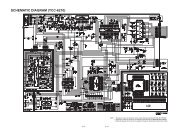
1 2 3 4KEH-1940,1960A3. BLOCK DIAGRAM AND SCHEMATIC DIAGRAM3.1 BLOCK DIAGRAMATUNER AMP UNITCN301BFM/AM TUNER UNITQ3FM RFT31 Q31 CF51FM/AM MIX FM/AM IFCF52FM IFCF53FM IFT51TUN-LILL+BBANT2526FMOSC34Q201 Q20241 9 10 14 15 17 19 47 1 263832 36 16FM/AM PROCESSORIC 1 PA4023B18232531 3028FM PROCESSORIC 2 PA4024A4043197FWDLchREVLchFWD-LFWDFMTVAMRF/AGCAMTVAMOSCAMIFCVCOCF232 AM IFFM+B AM+B TUN+BFMSDFMSL9AMSL18HEADREV-LML19 20 15 17 21 14 13 6GNDFIX+BQ804Q802B.UMMOTORDCASYSPW9V REGULATORQ803ILL+BCSLFMSD1412SLFMSDCKEYBOARSYSTEM CONTROLLERQ302Q303EOAMIFVCOQ806FIX+BFMQ805FIX+BAMIC 601 (1/2)PE5107AIL901-903LOOP FILTERQ304LWLWQ808FM SWITCHQ807AM SWITCHLW57EOAMIFVCOINFMAM3 13 6 54 51XIXO25 24KEY MATRIXX6014.5MHzD101 2 3 4
5 6 7 8KEH-1940,1960ATUN-LILL+BFWD-LFWD/REV SWITCH1REV-LFWD/REV6MUTE SWITCH8LOAD SWITCH9GND4168941CASSETTEEQUALIZERIC 201LA3161PMUTELOAD43FIX+B23MECHAPOWER SWITCHQ810ELECTRONICVOLUMEIC 401SN761029DLVDT/VCK/VST1920SYSPWMUTEQ6074Q60922Q501Q50265899POWER AMP FL+711FL-FL15 IC 501RL17TDA7384 RL+19RL-STBY MUTEFL+FL-RL+RL-B.UFL-FL+BD10CASSETTE PCB10CN601Q809Q601B.UMECPWDMINHB.UQ608CEVDD1VDD2Q606Q603ACC72FUSE10ABATTERYACCRL-RL+MECHA MUTEVDDBREQ604Q605B.UBOARD UNITTRIX24VDDKEY/LCDDRIVERIC 901PDC045A17RES15SCK14SO13SICN901435643CN602ILL+BSW5VSCK5SIO6Q602VDDSWVDD18SWVDD1 2MCMUTTAPLD63NOR/REV50MECPW39MUTE40DMINH7Q801B.UCE5SYSPWSYSPW43B REMOTEIC 801TPD1018FSYSPW61BRECN6031B REMOTECLCD 901CAW1568910LCKLDTSYSTEM CONTROLLERIC 601 (2/2)PE5107AD115 6 7 8
1 2 3 4KEH-1940,1960A3.2 OVERALL CONNECTION DIAGRAM(GUIDE PAGE)Note: When ordering service parts, be sure to refer to “EXPLODED VIEWS AND PARTS LIST” or “ELECTRICAL PARTSLIST”.A-aA-bLarge sizeSCH diagramATUNER AMP UNITBFM/AM TUNER UNITA-aELECTRONIC VOA-aA-bGuide pageA-aA-bDetailed pageAM : -26.0dBsFM : -16.0dBs-BSYSTEM CONTROLLERCEQ AMP-73dBsD12A DD CASSETTE PCB1 2 3 4
5 6 7 8KEH-1940,1960OLUMEA-bFM : 100% 35.1dBsAM : 30% 24.1dBsTAPE : 315Hz 0dB 22.1dBsA-29.0dBsPOWER AMPBACKUPANTRR RR- +FR FR- +FL FL- +GND ACCRL RL- +TAPE : -3.9dBsAM : -0.9dBsFM : 9.1dBsTAPE : 22.1dBsBFUSE600µHB.REMOTECKEY/LCD DRIVERCEL 1547(1940/X1M/EW)CEL 1479(1960/X1M/EW)14V 40mADCKEYBOARD UNIT5 6 7 8AC13
1 2 3 4KEH-1940,1960AA-a A-bELECTRONIC VOLUME-29.0dBsBAM : -26.0dBsFM : -16.0dBsCTUNER AMP UNITFM/AM TUNER UNIT12BDA14A-a1 2 3 4
5 6 7 8KEH-1940,1960A-a A-bASYSTEM CONTROLLERBCDD-73dBsEQ AMP345CASSETTE PCBA-a5 6 7 8D15
1 2 3 4KEH-1940,1960A600µHRR+GNDRL+FUSEBFM : 100% 35.1dBsAM : 30% 24.1dBsTAPE : 315Hz 0dB 22.1dBsTAPE : 22.1dBsRRFRFLRLFR+FL+A-a A-bBACKUPANTACC----POWER AMPCTAPE : -3.9dBsAM : -0.9dBsFM : 9.1dBsD16A-b121 2 3 4
5 6 7 8KEH-1940,1960A-a A-bAB.REMOTEBCCEL 1547(1940/X1M/EW)CEL 1479(1960/X1M/EW)14V 40mAKEY/LCD DRIVERKEYBOARD UNITCD345A-b5 6 7 8C17
1 2 3 4KEH-1940,19603.3 FM/AM TUNER UNITABFM/AM TUNER UNBDSP-201M-A11FCD21318B1 2 3 4
5 6 7 8KEH-1940,1960AAR UNITBCDB5 6 7 819
1 2 3 4KEH-1940,1960A4. PCB CONNECTION DIAGRAM4.1 TUNER AMP UNITNOTE FOR PCB DIAGRAMS1. The parts mounted on this PCBinclude all necessary parts forseveral destination.For further information forrespective destinations, be sureto check with the schematicdiagram.2. Viewpoint of PCB diagramsCORD ASSYConnectorCapacitorSIDE ABP.C.BoardChip PartSIDE BATUNER AMP UNITCD20A1 2 3 4
5 6 7 8KEH-1940,1960SIDE AABDCN1BCDCCN9015 6 7 8A21
1 2 3 4KEH-1940,1960A TUNER AMP UNITABCD22A1 2 3 4
5 6 7 8KEH-1940,1960SIDE BABCDA5 6 7 823
1 2 3 4KEH-1940,19604.2 FM/AM TUNER UNITASIDE ABCBFM/AM TUNER UNITAD24B1 2 3 4
1 2 3 4KEH-1940,1960SIDE BABCBFM/AM TUNER UNITD1 2 3 4B25
1 2 3 4KEH-1940,19604.3 KEYBOARD UNITSIDE ASIDE BABC1 2 3 4 5 6S CLOCK BSM LOCALA CN602DC KEYBOARD UNITTUNER BANDC KEYBOARD UNIT26C1 2 3 4
1 2 3 4KEH-1940,19604.4 CASSETTE PCBD CASSETTE PCBARRFRFLRLS1LOAD SWM1MOTORMHD1FWD/REVPB HEADS3FWD/REV SWCN11 3 5 7 9S2MUTE SWB2 4 6 8 10A CN601CD1 2 3 4D27
KEH-1940,19605. ELECTRICAL PARTS LISTNOTE:- Parts whose parts numbers are omitted are subject to being not supplied.- The part numbers shown below indicate chip components.Chip ResistorRS1/_S___J,RS1/__S___JChip Capacitor (except for CQS.....)CKS....., CCS....., CSZS.....=====Circuit Symbol and No.===Part Name Part No.--- ------ ------------------------------------------ -------------------------AUnit Number : CWM6740Unit Name : Tuner Amp UnitMISCELLANEOUSIC 201 IC LA3161PIC 401 IC SN761029DLIC 501 IC TDA7384IC 601 IC PE5107AIC 801 IC TPD1018FQ 301 Transistor 2SC1740SQ 302 Transistor 2SC1740SQ 303 Transistor 2SK330Q 304 Transistor DTC124ESQ 501 Transistor DTC124ESQ 502 Transistor DTC124ESQ 601 Transistor DTC114ESQ 602 Transistor 2SA933SQ 603 Transistor DTA114ESQ 604 Transistor 2SC1740SQ 605 Transistor 2SC1740SQ 606 Transistor 2SC1740SQ 607 Transistor 2SC1740SQ 608 Transistor DTC124TSQ 609 Transistor DTC143TSQ 801 Transistor 2SD1859Q 802 Transistor 2SB1238Q 803 Transistor DTC124ESQ 804 Transistor 2SD2395Q 805 Transistor 2SA933SQ 806 Transistor 2SA933SQ 807 Transistor DTC114ESQ 808 Transistor DTC114ESQ 809 Transistor DTC143TSQ 810 Transistor 2SB1242D 201 Diode 1SS270D 301 Diode MTZJ3R0(B)D 302 Diode 1SS270D 303 Diode 1SS270D 601 Diode 1SS270D 602 Diode 1SS270D 603 Diode 1SS270D 604 Diode 1SS270D 605 Diode HZS7L(A1)D 606 Diode 1SS270D 607 Diode 1SS270D 608 Diode 1SS270D 609 Diode HZS7L(A1)D 610 Diode HZS7L(C3)D 611 Diode HZS7L(B1)D 612 Diode 1SS270D 613 Diode 1SS270D 614 Diode 1SS270D 615 Diode HZS9L(A2)D 616 Diode 1SS270=====Circuit Symbol and No.===Part Name Part No.--- ------ ------------------------------------------ -------------------------D 617 Diode 1SS270D 801 Diode 1SR139-400D 802 Diode 1SR139-400D 803 Diode 1SR139-400D 804 Diode 1SR139-400D 805 Diode 1SR139-400D 806 Diode HZS6L(B2)D 807 Diode HZS9L(B3)L 601 Ferri-Inductor LAU2R2KL 602 Ferri-Inductor LAU2R2KL 801 Choke Coil 600µH CTH1168X 601 Crystal Resonator 4.500MHz CSS1077FM/AM Tuner UnitCWE1466RESISTORSR 201 RS1/10S104JR 202 RS1/10S104JR 203 RS1/10S472JR 204 RS1/10S472JR 205 RS1/10S470JR 206 RS1/10S470JR 207 RS1/10S273JR 208 RS1/10S273JR 301 RS1/10S102JR 302 RS1/10S222JR 303 RS1/10S222JR 304 RD1/4PU102JR 305 RS1/10S102JR 313 RS1/8S223JR 314 RD1/4PU103JR 315 RS1/10S102JR 316 RS1/10S472JR 317 RS1/10S152JR 318 RD1/4PU222JR 319 RS1/10S222JR 320 RS1/10S102JR 321 RD1/4PU103JR 322 RS1/10S393JR 323 RS1/10S0R0JR 324 RS1/10S0R0JR 325 RD1/4PU101JR 331 RS1/8S0R0JR 401 RS1/10S272JR 402 RS1/10S272JR 403 RS1/10S0R0JR 405 RS1/10S272JR 406 RS1/10S272JR 407 RS1/10S151JR 408 RS1/10S151JR 501 RS1/10S153JR 502 RS1/10S221JR 503 RS1/10S101JR 504 RD1/4PU153JR 601 RD1/4PU102JR 602 RS1/10S473J28
KEH-1940,1960=====Circuit Symbol and No.===Part Name Part No.--- ------ ------------------------------------------ -------------------------R 603 RS1/10S103JR 604 RD1/4PU332JR 605 RS1/10S473JR 606 RS1/10S222JR 607 RS1/10S222JR 608 RD1/4PU473JR 609 RS1/10S123JR 612 RD1/4PU472JR 613 RD1/4PU473JR 614 RS1/10S473JR 615 RS1/10S222JR 616 RD1/4PU222JR 617 RD1/4PU222JR 618 RS1/10S1R0JR 621 RD1/4PU222JR 622 RS1/10S473JR 623 RS1/10S472JR 624 RS1/10S223JR 625 RS1/10S103JR 626 RS1/10S223JR 627 RS1/10S103JR 628 RS1/10S104JR 629 RS1/10S223JR 630 RS1/10S103JR 631 RD1/4PU472JR 632 RS1/10S472JR 633 RS1/10S103JR 634 RS1/10S223JR 635 RD1/4PU152JR 636 RD1/4PU103JR 637 RD1/4PU472JR 640 RS1/10S472JR 801 RD1/4PU102JR 803 RS1/10S103JR 804 RS1/10S223JR 805 RD1/4PU331JR 806 RD1/4PU331JR 807 RD1/4PU511JR 808 RS1/10S472JR 809 RS1/10S102JR 810 RS1/10S472JR 811 RS1/10S102JR 812 RS1/10S472JR 813 RD1/4PU102JR 814 RD1/4PU1R5JR 815 RD1/4PU1R5JR 816 RD1/4PU103JCAPACITORSC 201 CEJA2R2M50C 202 CEJA2R2M50C 203 CKSQYB333K25C 204 CKSQYB333K25C 205 CEJA101M10C 206 CEJA101M10C 207 CKSQYB681K50C 208 CKSQYB681K50C 209 CEJA101M10C 301 CKSQYB473K25C 302 CKSQYB104K16C 303 CKSQYB223K50C 304 CKSQYB104K16C 305 CKSQYB223K50C 306 CKSQYB102K50C 307 CKSQYB103K50C 308 CCSQCH101J50C 311 CCSQCH101J50C 313 CKLSR473K16C 314 CKSQYB102K50=====Circuit Symbol and No.===Part Name Part No.--- ------ ------------------------------------------ -------------------------C 315 4.7µF/16V CCH1250C 316 CKSQYB103K50C 317 CEJAR47M50C 318 CKSQYB223K50C 319 CKSQYB223K50C 401 CKSQYB223K50C 402 CKSQYB223K50C 403 CEJA1R0M50C 404 CEJA1R0M50C 405 CEJA1R0M50C 406 CEJA1R0M50C 407 CEJA100M16C 408 CEJA100M16C 409 CKSQYB822K50C 410 CKSQYB822K50C 411 CEJA1R0M50C 412 CEJA1R0M50C 413 CKSQYB153K50C 414 CKSQYB153K50C 415 CKSQYB104K16C 416 CKSQYB104K16C 417 CKSQYB104K16C 418 CKSQYB104K16C 419 CKSQYB104K16C 420 CEJA470M10C 421 CEJA2R2M50C 422 CEJA4R7M35C 423 CKSQYB473K25C 424 CEJA1R0M50C 427 CCSQCH240J50C 428 CCSQCH330J50C 501 CFTNA224J50C 502 CFTNA224J50C 503 CFTNA224J50C 504 CFTNA224J50C 505 CEJA330M10C 506 CEJA2R2M50C 507 CFTNA105J50C 508 CEJA100M16C 510 CKSQYB104K50C 601 CKSQYB104K16C 602 CKSQYB102K50C 603 CEJA4R7M35C 604 CKSQYB224K16C 605 CKSQYB102K50C 606 CCSQCH100D50C 607 CCSQCH110J50C 608 CKSQYB103K50C 611 CKSQYB472K50C 801 3300µF/16V CCH1369C 802 CKSQYB103K50C 803 CKSYB103K50C 804 CEAS331M16C 805 CKSQYB102K50C 806 330µF/10V CCH1181C 807 CKSQYB103K50C 808 330µF/10V CCH1181C 809 CCSQCH101J50C 810 CCSQCH101J50BUnit Number : CWE1466Unit Name : FM/AM Tuner UnitMISCELLANEOUSIC 1 IC PA4023BIC 2 IC PA4024AQ 1 Transistor 2SC2412KQ 2 Transistor DTC124EUQ 3 FET 3SK26329
KEH-1940,1960=====Circuit Symbol and No.===Part Name Part No.--- ------ ------------------------------------------ -------------------------Q 31 Transistor 2SC2412KQ 154 Transistor DTC124EUQ 165 Transistor 2SC2412KQ 201 FET 2SK932Q 202 Transistor 2SC2412KQ 203 Transistor DTC124EUD 4 Diode 1SV250D 5 Diode KV1410-F1D 7 Diode KV1410-F1D 8 Diode KV1410-F1D 201 Diode MA157D 202 Diode MA157D 231 Diode SVC253L 2 Coil CTC1133L 3 Inductor LCTB2R2K2125L 4 Coil CTC1133L 5 Coil CTC1132L 6 Inductor LCTBR15K1608L 51 Ferri-Inductor LAU150KL 201 Ferri-Inductor LAU4R7KL 202 Ferri-Inductor LAU330KL 203 Inductor CTF1287L 208 Inductor LAU121KL 231 Inductor LCTA3R3J3225T 31 Coil CTE1116T 51 Coil CTC1136TC 1 CCL1038CF 51 Ceramic Filter CTF1442CF 52 Ceramic Filter CTF1442CF 53 Ceramic Filter CTF1442CF 232 Ceramic Filter CTF1348X 151 Radiator 918.5Hz CSS1365X 231 Crystal Resonator 10.26MHz CSS1111VR 154 Semi-fixed 150kΩ(B) CCP1213AR 1 DSP-201M-A11FRESISTORSR 1 RS1/16S0R0JR 4 RS1/16S154JR 5 RS1/16S391JR 6 RS1/16S223JR 7 RS1/16S123JR 8 RS1/16S332JR 9 RS1/16S473JR 10 RS1/16S223JR 11 RS1/16S124JR 13 RS1/16S563JR 15 RS1/16S271JR 16 RS1/16S104JR 17 RS1/16S332JR 18 RS1/16S332JR 31 RS1/16S470JR 32 RS1/16S822JR 33 RS1/16S822JR 34 RS1/16S331JR 35 RS1/16S331JR 40 RS1/16S470JR 51 RS1/16S271JR 52 RS1/16S560JR 55 RS1/16S102JR 56 RS1/16S823JR 61 RS1/16S392JR 62 RS1/16S393JR 101 RS1/16S272JR 102 RS1/16S682JR 103 RS1/16S333JR 104 RS1/16S334J=====Circuit Symbol and No.===Part Name Part No.--- ------ ------------------------------------------ -------------------------R 105 RS1/16S683JR 107 RS1/16S222JR 151 RS1/16S222JR 152 RS1/16S393JR 154 RS1/16S104JR 155 RS1/16S273JR 156 RS1/16S243JR 157 RS1/16S203JR 160 RS1/16S222JR 161 RS1/16S563JR 162 RS1/16S105JR 163 RS1/16S222JR 202 RS1/16S223JR 203 RS1/16S225JR 204 RS1/16S103JR 206 RS1/16S220JR 207 RS1/16S101JR 208 RS1/16S102JR 209 RS1/16S471JR 214 RS1/16S822JR 215 RS1/16S822JR 217 RS1/16S102JR 231 RS1/16S272JR 232 RS1/16S473JR 237 RS1/16S103JR 238 RS1/16S104JR 239 RS1/16S104JR 240 RS1/16S332JR 241 RS1/16S202JR 243 RS1/16S123JR 244 RS1/16S103JR 247 RS1/16S123JCAPACITORSC 1 CCSQCH6R0D50C 2 CCSRCK2R0C50C 4 CCSRCH820J50C 6 CCSRCH820J50C 8 CKSRYB103K25C 9 CKSQYB104K16C 10 CCSRCKR50C50C 11 CEJA1R0M50C 13 CKSRYB222K50C 14 CCSRCH220J50C 16 CCSRCH8R0D50C 17 CKSRYB222K50C 18 CKSRYB103K25C 19 CKSRYB222K50C 20 CKSRYB222K50C 21 CEJA100M16C 22 CCSRTH9R0D50C 23 CCSRTH120J50C 24 CCSRCH471J50C 25 CKSRYB103K25C 31 CKSRYB103K25C 32 CKSQYB472K50C 33 CCSRCH5R0C50C 34 CKSQYB104K16C 36 CCSRRH201J50C 51 CKSRYB223K25C 52 CKSRYB103K25C 54 CCSRCH470J50C 55 CKSQYB223K25C 56 CKSQYB104K16C 57 CKSRYB472K50C 58 CEJA330M10C 59 CKSRYB103K25C 61 CCSRCH270J50C 62 CKSRYB103K2530
KEH-1940,1960=====Circuit Symbol and No.===Part Name Part No.--- ------ ------------------------------------------ -------------------------C 63 CEJAR15M50C 101 CEJANP100M10C 102 CKSRYB182K50C 103 CKSRYB682K25C 104 CEJA2R2M50C 105 CKSRYB103K25C 106 CCSRCH151J50C 107 CKSRYB103K25C 151 CKSRYB472K50C 152 CKSQYB104K16C 153 CEJA3R3M50C 154 CKSQYB104K16C 157 CEJA3R3M50C 158 CKSYB474K16C 159 CEJA220M6R3C 160 CKSQYB104K16C 161 CKSQYB104K16C 162 CEJA3R3M50C 163 CKSRYB102K50C 170 CCSRCH100D50C 201 CCSRCH471J50C 202 CCSRCH100D50C 203 CKSRYB332K50C 204 CKSQYB473K16C 205 CKSQYB473K16C 206 CKSQYB104K16C 207 CCSRCH560J50C 209 CKSQYB104K16C 211 CCSRCH101J50C 212 CEJA470M6R3=====Circuit Symbol and No.===Part Name Part No.--- ------ ------------------------------------------ -------------------------IL 901 Lamp 14V 40mA (1960/X1M/EW) CEL1479IL 902 Lamp 14V 40mA (1940/X1M/EW) CEL1547IL 902 Lamp 14V 40mA (1960/X1M/EW) CEL1479IL 903 Lamp 14V 40mA (1940/X1M/EW) CEL1547IL 903 Lamp 14V 40mA (1960/X1M/EW) CEL1479LCD 901 LCD CAW1568RESISTORSR 901 RS1/10S222JR 902 RS1/10S222JR 905 RS1/10S682JR 906 RS1/10S473JR 907 RS1/10S472JCAPACITORSC 901 CCSQCH181J50C 902 CKSQYB103K50C 903 CKSQYB103K50C 905 CKSQYB104K16C 906 10µF/16V CCH1370DUnit Number :Unit Name : Cassette PCBS 1 Swicth(Load) ESN1016S 2 Swicth(Mute) ESN1017S 3 Swicth(FWD/REV) ESH1006Miscellaneous Parts ListM 1 Motor Unit EXA1467HD 1 Head Assy EXA1466C 213 CKSRYB103K25C 216 CCSRCH101J50C 217 CEJA1R5M50C 219 CCSRCH471J50C 220 CKSRYB103K25C 230 CKSRYB103K25C 231 CCSRCH330J50C 232 CCSRCH150J50C 233 CKSQYB104K16C 234 CEJA330M10C 235 CKSRYB332K50C 236 CKSQYB473K16C 237 CCSRCH120J50C 239 CKSRYB472K50C 240 CEJAR47M50C 241 CKSQYB104K16C 242 CEJAR47M50C 243 CEJAR33M50C 244 CKSQYB473K16C 245 CKSRYB123K25C 246 CKSQYB473K16C 250 CCSRCH471J50CUnit Number : CWM6745(KEH-1940/X1M/EW): CWM6746(KEH-1960/X1M/EW)Unit Name : Keyboard UnitMISCELLANEOUSIC 901 IC PDC045AD 901 Diode MA153D 902 Diode MA153D 903 Diode MA110IL 901 Lamp 14V 40mA (1940/X1M/EW) CEL154731
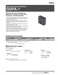
KEH-1940,19606. ADJUSTMENT- Connection DiagramBACK UPACCGND+14.4VGNDDC RegulatedPower SupplyLch +Lch -Rch +4ΩmV Meter (1)OscilloscopeRch -4ΩAntenna PlugDummy Antenna50Ω (37.5Ω )50Ω (75Ω )FM SSGStereoModulatorAntenna JackTUNER AMP UNITFM/AM TUNER UNIT (TOP VIEW)L2Pin26Pin 19FM/AM TUNER UNITT31L4TC1L5Pin14DC VMeter(1)Pin13T51VR154Pin1FM/AM TUNER UNIT (BOTTOM VIEW)T51CenterMeterC6332
KEH-1940,1960FM ADJUSTMENTModulation M:MONO MOD., 400Hz 30%(22.5kHz Dev.) or 400Hz 100%(75kHz Dev.)S:STEREO MOD., 1kHz, L or R=30%(20.25kHz+7.5kHz Dev.)NOTE:Before proceeding to further adjustments after switching power ON, let the tuner <strong>ru</strong>n for ten minutes to allowthe circuits to stabilize.FM SSG Displayed Adjustment Adjustment MethodNo. Frequency(MHz) Level(dBf) Frequency(MHz) Point (Switch Position)TUN Volt 1 ••••• ••••• 108.0 L5 DC V Meter(1) : 6VIF 2 98.1 M 60—100 98.1 T51 Center Meter : 0ANT Coil 3 98.1 M 5 98.1 L2 mV Meter(1) : MaximumRF Coil 4 98.1 M 5 98.1 L4 mV Meter(1) : MaximumRF 5 129.3 M 60—80 107.9 TC1 mV Meter(1) : MinimumTrimmer6 RF Coil and RF Trimmer shall be adjusted twice or moreIFT 7 98.1 M 5 98.1 T31 mV Meter(1) : Maximum(STEREO MODE)ARC 8 98.1 S 40 98.1 VR154 mV Meter(1) : Separation 5dB(STEREO MODE)33
KEH-1940,19607. GENERAL INFORMATION7.1 DISASSEMBLY- Remove the Case(not shown)1.Remove the three screws.2.Remove the Case.- Remove the Cassette Mechanism Assy(not shown)1.Remove the four screws.2.Disconnect the connector, and then remove theCassette Mechanism Assy.- Remove the Panel Unit(Fig.1)Cassette Mechanism AssyDisengage the stopper at two locationsindicated by arrow.Remove the Panel Unit.Panel UnitFig.1- Remove the Tuner Amp Unit(Fig.2)Remove the two screws.Remove the three screws.Remove the screw.Unbend the tabs at four locations indicatedby arrow until straight.Remove the Tuner Amp Unit.Tuner Amp UnitFig.234
KEH-1940,19607.2 PARTS7.2.1 ICSN761029DLAVccIN1-LIN2-LIN3-LIN4(+)-LIN4(-)-LAGNDSWout-LZCin-LLOUD-LVRin-LTREB-LBASS-C1-LBASS-R-LBASS-C2-LNCTONEout-LFADERin-LFRNTout-LREARout-LVREFinAGNDDGNDCt1 2 3 4 5 6 7 8 9 10 11 12 13 14 15 16 17 18 19 20 21 22 23 24IsolatorVolume,Loudness Treble BassFaderPowerSupplyAGainAdjustPowerSupplyAZero-crossDetector3 Line Serial BusGainAdjustVolume, TrebleLoudnessBassFaderIsolator48 47 46 45 44 43 42 41 40 39 38 37 36 35 34 33 32 31 30 29 28 27 26 25VCCIN1-RIN2-RIN3-RIN4(+)-RIN4(-)-RAGNDSWout-RZCin-RLOUD-RVRin-RTREB-RBASS-C1-RBASS-R-RBASS-C2-RNCTONEout-RFADERin-RFRNTout-RREARout-RDVccDATACLKSTB35
KEH-1940,1960- Pin Functions (PE5107A)Pin No. Pin Name I/O Format Function and Operation1 mcmute I Cassette mechanism mute input2 tapld I Tape loading input3 EO O C Error output4 VDD1 Power supply5 GND GND6 VCOIN I AM/FM VCO input7 CE I ACC power sense input8 VDD2 Power supply9 LCK I/O C Serial clock input and output for LCD driver10 LDT O C Data output for LCD driver11 LDI I Key/LCD driver data input12 FMSD I FM SD input13 AMIF I AM IF signal input14 SL I Signal level input15 st I FM stereo input16 sk Not used17 DK Not used18 swvdd O C Grille power supply control output19 NC Not used20 VST O C Strobe pulse output for electronic volume21 VCK O C Clock output for electronic volume22 VDT O C Data output for electronic volume23 NC Not used24 XO O Crystal oscillator connection pin25 XI I Crystal oscillator connection pin26 GND GND27–30 NC Not used31 TEST I Test program mode input32 dsens I Grille detach sense input33,34 GND GND35–38 NC Not used39 mute O C System mute output40 DMINH O C Mechanism mute cancel output41,42 NC Not used43 SYSPW O C System power supply control output44–48 NC Not used49 MS Not used50 MECPW O C Cassette mechanism power output51 AM O C AM power control output52 LOCL O C LOC “L“ output53 LOCH O C LOC “H” output54 FM O C FM power control output55 seek O C Seek output56 NC Not used57 LW O C LW output58 GND GND59 DM3 Not used60 DM2 Not used61 DM1 I Model,function input62 DM0 I Model,function input63 nor/REV I Tape <strong>ru</strong>nning input64 GND GND36
KEH-1940,1960*PE5107A52513332IC's marked by* are MOS type.Be careful in handling them because they are veryliable to be damaged by electrostatic induction.6420FormatCMeaningC MOS119- Pin Functions(PDC045A)Pin No. Pin Name I/O Function and Operation1–4 NC Not used5–8 KS4-1 O Key strobe output9–12 KD4-1 I Key data input13 SI I Display data input14 SO O Key data output15 SCK I/O Clock input terminal for serial data input and output16 REMIN I Remote control reception17 RES I Reset input18 TEST I Test input19 OSC-IN I System clock input20 OSC-OUT O System clock output21 GND GND22,23 VDD2,1 LCD power supply24 VDD Power supply25–28 COM1-4 O LCD common signal29–42 SEG1-14 O LCD segment signal43–48 NC Not used*PDC045A24132512361374837
KEH-1940,19607.2.2 DISPLAY- CAW1568SEGMENTCOMMON38
KEH-1940,19608. OPERATIONS AND SPECIFICATIONS5793.Connect leads of the samecolor to each other.7.YellowBack-up (or Accessory)9.RedAccessory (or Back-up)11.ISO connectorNote:In some vehicles, the ISO connector may bedivided into two. If this is the case, be sure toconnect to both connectors.685.Cap1.This Product2.Antenna jack4.Note:Depending on the kind of vehicle, thefunction of 7 and 9 may be different.If this is the case, be sure to connect6to9and7to8.When the power cord of the otherproduct is connected to terminal 5,check the function of the terminal 5(Back up or Accessory) beforehand.6.YellowT o terminal always supplied with powerregardless of ignition switch position.8.RedTo electric terminal controlled by ignitionswitch (12 V DC) ON/OFF.10.Black (ground)To vehicle (metal) body.12.Speaker leadsWhite: Front left +White/black: Front left ≠Gray: Front right +Gray/black: Front right ≠Green: Rear left +Green/black: Rear left ≠Violet: Rear right +Violet/black: Rear right ≠15.Fuse13.Blue/whiteTo Auto-antenna relay control terminal.(Max. 300 mA 12 V DC.)14. Blue/whiteThe pin position of the ISO connectorwill differ according to the type ofvehicle. Connect 13 and 14 when Pin 5 isan antenna control type. In another typeof vehicle, never connect 13 and 14.39
KEH-1940,19608.1 OPERATIONSKey FinderHead UnitBAND button 22/33 buttonsTUNER buttonCassette door EJECT buttonDetach button2/3 buttonsCLOCKbuttonLOCAL buttonButtons 1–6+/– buttonsSHIFT/LOUDbuttonBSM buttonBasic OperationTo Listen to MusicThe following explains the initial operations required before you can listen to music.Note:• Loading a cassette in this product.1. Press the TUNER button to switch the Tuner ON/OFF.Note:• You cannot switch to the Tuner when a tape is loaded.• You cannot switch to the Cassette Player when a tape is not loaded.• When this product’s blue/white lead is connected to the car’s Auto-antenna relay control terminal,the car’s Auto-antenna extends when this product’s power is switched ON. To retract the antenna,switch the power OFF.2. Raise or lower the volume.3. Turn the Tuner OFF.40
KEH-1940,1960Basic OperationBasic Operation of Tuner<strong>Manual</strong> and Seek Tuning• Press 2 or 3 to select a station.Note:• You can select the tuning method by pressing the 2 and 3 buttons at thesame time.• When the Seek Tuning is selected, “SEEK” lights in the display.• When the <strong>Manual</strong> Tuning is selected, “SEEK” goes out from the display.• Stereo indicator “apple” lights when a stereo station is selected.BandFI (FM1) = FII (FM2) = FIII (FM3)= M/L (MW/LW)Frequency IndicatorBand IndicatorPreset TuningPreset Number Indicator• You can memorize broadcast stations in buttons1 through 6 for easy, one-touch station recall.Preset station recall 2 seconds or lessBroadcast station preset memory 2 seconds or moreNote:• Up to 18 FM stations (6 in FI (FM1), FII (FM2) and FIII(FM3)) and 6 MW/LW stations (6 in M/L) can be stored inmemory.Basic Operation of Cassette PlayerFast Forward/Rewind• To select Fast Forward, press the button for the same direction asthe tape play indicator.• To select Rewind, press the button for the opposite direction as thetape play indicator.Note:• To release Fast Forward/Rewind, lightly press the 1 or ¡ button located on theopposite side of the one you pressed to Fast Forward or Rewind.Direction ChangeCassette Loading SlotYou can listen to a tape if it isset to this product even whenlistening to the Tuner.• To change thedirection, pressthe 1 and ¡buttons at thesame time.EjectThe power of this product turns OFFwhen you eject a tape with the EJECTbutton.When you listen to the Tuner before atape is set to this product, the sourceswitches to the radio.Tape Play Indicator41
KEH-1940,19608.2 SPECIFICATIONSSpecificationsGeneralPower source .......... 14.4 V DC (10.8 – 15.1 V allowable)Grounding system ........................................ Negative typeMax. current consumption ........................................ 8.5 ADimensions(mounting size) ...... 178 (W) × 50 (H) × 150 (D) mm(front face) .............. 188 (W) × 58 (H) × 20 (D) mmWeight ...................................................................... 1.2 kgAmplifierMaximum power output ...................................... 40 W × 4Continuous power output .................................... 22 W × 4(DIN45324, +B = 14.4 V)Load impedance .......................... 4 Ω (4 – 8 Ω allowable)Tone controls(Bass) .............................................. ±12 dB (100 Hz)(Treble) ............................................ ±12 dB (10 kHz)Loudness contour ..........+10 dB (100 Hz), +7 dB (10 kHz)(volume: –30 dB)Cassette playerTape ........................ Compact cassette tape (C-30 – C-90)Tape speed ...... 4.76 cm/sec.(+0.14 cm/sec.,-0.05 cm/sec.)Fast forward/rewinding time ...... Approx. 90 sec. for C-60Wow & flutter .......................................... 0.13% (WRMS)Frequency response ...................... 40 – 14,000 Hz (±3 dB)Stereo separation ...................................................... 45 dBSignal-to-noise ratio...................... 52 dB (IEC-A network)FM tunerFrequency range ...................................... 87.5 – 108 MHzUsable sensitivity .................................................... 11 dBf(1.0 µV/75 Ω, mono, S/N: 30 dB)50 dB quieting sensitivity ........................................ 16 dBf(1.7 µV/75 Ω, mono)Signal-to-noise ratio ...................... 70 dB (IEC-A network)Distortion .......................... 0.3% (at 65 dBf, 1 kHz, stereo)Frequency response ...................... 30 – 15,000 Hz (±3 dB)Stereo separation .......................... 40 dB (at 65 dBf, 1 kHz)MW tunerFrequency range ...................................... 531 – 1,602 kHzUsable sensitivity .............................. 18 µV (S/N: 20 dB)Selectivity .................................................. 50 dB (±9 kHz)LW tunerFrequency range ........................................ 153 – 281 kHzUsable sensitivity .............................. 30 µV (S/N: 20 dB)Selectivity .................................................. 50 dB (±9 kHz)Note:• Specifications and the design are subject topossible modification without notice due toimprovements.