Extruded EMI Gaskets - Toptronic A/S
Extruded EMI Gaskets - Toptronic A/S
Extruded EMI Gaskets - Toptronic A/S

Create successful ePaper yourself
Turn your PDF publications into a flip-book with our unique Google optimized e-Paper software.
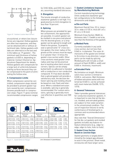
XFigure 10. Fastener Location Near Cornersencountered, or where low closureforces are required. Hollow gasketsare often less expensive, and theycan be obtained with or without attachmenttabs. Hollow gaskets withtabs are referred to in the text andin the tables as “P-gaskets”. Theminimum wall thickness of hollowgaskets is 0.020 in. depending onmaterial. Contact Chomerics’ ApplicationsDepartment for details.Hollow gaskets will compensate fora large lack of uniformity betweenmating surfaces because they canbe compressed to the point of eliminatingthe hollow area.4. Compression LimitsWhen compression cannot be controlled,compression stops shouldbe provided to prevent gasket rupturecaused by over-compression.Grooves provide built-in compressionstops. Figure 11 gives nominalrecom mended compression rangesØWX/2Figure 11. Gasket Deflection RangesWHX/2Xfor CHO-SEAL and CHO-SIL materials,assuming standard tolerances.5. ElongationThe tensile strength of conductiveelastomer gaskets is not high. It isgood practice to limit elongation toless than 10 percent.6. SplicingWhen grooves are provided for gasketcontainment, two approachesare possible. A custom gasket canbe molded in one piece and placedinto the desired groove, or a stripgasket can be spliced to length andfitted to the groove. To properlyseat a spliced solid “O” cross sectiongasket, the inner radius of thegroove at the corners must be equalto or greater than 1.5 times thegasket cross section width. Othercross sections need greater innerradius and may not be practicaldue to twisting when bent aroundcorners. Splices can be simplybutted (with no adhesive) or bondedwith a conductive or non-conductivecompound. If it has been decidedthat a spliced gasket will provide asatisfactory seal, the decision betweensplicing and molding shouldbe based on cost, flash and tolerance.When a standard extrusionis available, splicing is generallyrecommended. For custom extrusions,splicing is generally morecost effective in quantities over 500feet.Deflection Deflection Deflection DeflectionRange ØW Range H Range T Range A ØB0.007-0.018 0.070 0.005-0.014 0.068 0.001-0.003 0.020 0.020-0.080 0.200 0.080(0.178-0.457) (1.778) (0.127-0.356) (1.727) (0.025-0.076) (0.508) (0.508-2.032) (5.08) (2.032)0.010-0.026 0.103 0.007-0.018 0.089 0.002-0.005 0.032 0.025-0.125 0.250 0.125(0.254-0.660) (2.616) (0.178-0.457) (2.261) (0.051-0.127) (0.813) (0.635-3.175) (6.35) (3.175)0.013-0.031 0.125 0.010-0.026 0.131 0.003-0.009 0.062 0.036-0.255 0.360 0.255(0.330-0.787) (3.175) (0.254-0.660) (3.327) 0.076-0.229) (1.575) (0.914-6.477) (9.144) (6.477)0.014-0.035 0.139 0.012-0.031 0.156 0.005-0.014 0.093(0.356-0.889) (3.531) (0.305-0.787) (3.962) (0.127-0.356) (2.362)0.014-0.035 0.175(0.356-0.889) (4.445)T(mm dimensions in parentheses)AØB7. Gasket Limitations Imposedby Manufacturing MethodsCurrent manufacturing technologylimits conductive elastomer gasketconfigurations to the followingdimensions and shapes :■ Die-cut PartsMaximum Overall Size: 32 in. long x32 in. wide x 0.125 in. thick (81 cm x81 cm x 3.18 mm)Minimum Cross Section: Width-tothicknessratio 1:1 (width is not to beless than the thickness of the gasket).■ Molded PartsCurrently available in any solidcross section, but not less than0.040 in. in diameter. The outer dimensionsof the gasket are limitedto 34 inches in any direction. Largerparts can be made by splicing.Molded parts will include a smallamount of flash (0.008 in. width and0.005 in. thickness, maximum).■ <strong>Extruded</strong> PartsNo limitation on length. Minimumsolid cross-section is limited to0.028 in. extrusions. Wall thicknessof hollow extrusions varies with materialbut 0.020 in. can be achievedwith most materials (S6308, 1215,1273).8. General TolerancesTable 4 provides general tolerancesfor conductive elastomer gaskets. Itis important to note that all flat diecut,molded, and extruded gasketsare subject to free-state variationin the unrestrained condition. Theuse of inspection fixtures to verifyconformance of finished parts iscommon and recommended whereappropriate.Also note that “Overall Dimensions”for flat die-cut gaskets and moldedgaskets includes any feature-tofeaturedimensions (e.g., edge-toedge,edge-to-hole, hole-to-hole).9. Gasket Cross SectionBased on Junction GapsGasket geometry is largely determinedby the largest gap allowedto exist in the junction. Sheet metalenclosures will have larger varia-Chomerics 58