Extruded EMI Gaskets - Toptronic A/S
Extruded EMI Gaskets - Toptronic A/S
Extruded EMI Gaskets - Toptronic A/S

Create successful ePaper yourself
Turn your PDF publications into a flip-book with our unique Google optimized e-Paper software.
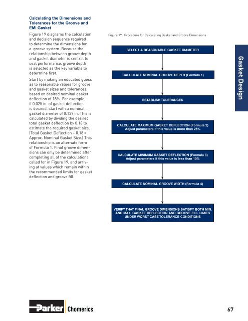
Calculating the Dimensions andTolerances for the Groove and<strong>EMI</strong> GasketFigure 19 diagrams the calculationand decision sequence requiredto determine the dimensions fora groove system. Because therelationship between groove depthand gasket diameter is central toseal performance, groove depthis selected as the key variable todetermine first.Start by making an educated guessas to reasonable values for grooveand gasket sizes and tolerances,based on desired nominal gasketdeflection of 18%. For example,if 0.025 in. of gasket deflectionis desired, start with a nominalgasket diameter of 0.139 in. This iscalculated by dividing the desiredtotal gasket deflection by 0.18 toestimate the required gasket size.(Total Gasket Deflection ÷ 0.18 =Approx. Nominal Gasket Size.) Thisrelationship is an alternate formof Formula 1. Final groove dimensionscan only be determined aftercompleting all of the calculationscalled for in Figure 19, and arrivingat values which remain withinthe recommended limits for gasketdeflection and groove fill.Figure 19. Procedure for Calculating Gasket and Groove DimensionsSELECT A REASONABLE GASKET DIAMETERCALCULATE NOMINAL GROOVE DEPTH (Formula 1)ESTABLISH TOLERANCESCALCULATE MAXIMUM GASKET DEFLECTION (Formula 2)Adjust parameters if this value is more than 25%CALCULATE MINIMUM GASKET DEFLECTION (Formula 3)Adjust parameters if this value is less than 10%Gasket DesignCALCULATE NOMINAL GROOVE WIDTH (Formula 4)VERIFY THAT FINAL GROOVE DIMENSIONS SATISFY BOTH MIN.AND MAX. GASKET DEFLECTION AND GROOVE FILL LIMITSUNDER WORST-CASE TOLERANCE CONDITIONSChomerics 67