Reflective Optical Sensor with Transistor Output
Reflective Optical Sensor with Transistor Output
Reflective Optical Sensor with Transistor Output

You also want an ePaper? Increase the reach of your titles
YUMPU automatically turns print PDFs into web optimized ePapers that Google loves.
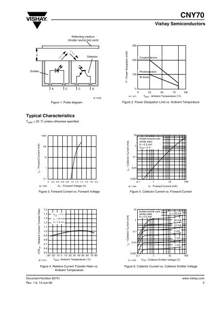
CNY70Vishay SemiconductorsReflecting medium(Kodak neutral test card)300dEmitter~ ~~~ ~~DetectorP - Power Dissipation (mW)200100Coupled devicePhototransistorIR-diodeA C C EFigure 1. Pulse diagram95 10808095 110710 25 50 75 100T amb - Ambient Temperature (°C)Figure 2. Power Dissipation Limit vs. Ambient TemperatureTypical CharacteristicsT amb = 25 °C unless otherwise specifiedI F - Forward Current (mA)1000100101Collector Current (mA)I –C1010.10.01Kodak neutral card(white side)d= 0.3 mmV CE =5V0.10 0.2 0.4 0.6 0.8 1.0 1.2 1.4 1.6 1.8 2.096 11862 V F - Forward Voltage (V)Figure 3. Forward Current vs. Forward Voltage0.0010.1 1 1095 11065I F - Forward Current (mA)100Figure 5. Collector Current vs. Forward CurrentCTR rel - Relative Current Transfer Ratio1.51.41.31.21.11.00.90.80.70.696 11913V = 5 VCEIF= 20 mAd = 0.3 mm0.5- 30 - 20 - 10 0 10 20 30 40 50 60 70 80T amb - Ambient Temperature (°C)Collector Current (mA)I –C1010.10.0195 11066Kodak neutral card(white side)d= 0.3 mm0.0010.1 1 10I F =5 0m A20 mA10 mA5m A2m A1m AV CE - Collector Emitter Voltage (V)100Figure 4. Relative Current Transfer Ratio vs.Ambient TemperatureDocument Number 83751Rev. 1.6, 13-Jun-06Figure 6. Collector Current vs. Collector Emitter Voltagewww.vishay.com3