ETAG 034 Edition July 2011 GUIDELINE FOR EUROPEAN ...
ETAG 034 Edition July 2011 GUIDELINE FOR EUROPEAN ...
ETAG 034 Edition July 2011 GUIDELINE FOR EUROPEAN ...

Create successful ePaper yourself
Turn your PDF publications into a flip-book with our unique Google optimized e-Paper software.
European Organisation for Technical ApprovalsEuropäische Organisation für Technische ZulassungenOrganisation Européenne pour l’Agrément Technique<strong>ETAG</strong> <strong>034</strong><strong>Edition</strong> <strong>July</strong> <strong>2011</strong><strong>GUIDELINE</strong> <strong>FOR</strong> <strong>EUROPEAN</strong> TECHNICAL APPROVALofKITS <strong>FOR</strong> EXTERNALWALL CLADDINGSPart I : VENTILATED CLADDING KITS COMPRISING CLADDINGCOMPONENTS AND ASSOCIATED FIXINGSE O T A©Kunstlaan 40 Avenue des ArtsB - 1040 BRUSSEL<strong>ETAG</strong> <strong>034</strong>1
TABLE OF CONTENTS<strong>FOR</strong>EWORD..........................................................................................................................................................6BACKGROUND OF THE <strong>ETAG</strong> ...............................................................................................................................6REFERENCE DOCUMENTS ......................................................................................................................................6UPDATING CONDITIONS ........................................................................................................................................6SECTION ONE: INTRODUCTION....................................................................................................................71. PRELIMINARIES .........................................................................................................................................71.1 LEGAL BASIS.............................................................................................................................................71.2 STATUS OF ETA-<strong>GUIDELINE</strong>S....................................................................................................................72 SCOPE ............................................................................................................................................................82.1 SCOPE .......................................................................................................................................................82.2 USE CATEGORIES, PRODUCTS FAMILIES, KITS..........................................................................................102.2.1 Claddings families..........................................................................................................................102.2.2 Use categories................................................................................................................................162.3 ASSUMPTIONS.........................................................................................................................................163 TERMINOLOGY ........................................................................................................................................163.1 COMMON TERMINOLOGY AND ABBREVIATIONS ......................................................................................163.2 SPECIFIC TERMINOLOGY .........................................................................................................................163.2.1 Substrate.........................................................................................................................................163.2.2 Subframe ........................................................................................................................................173.2.3 Cladding element ...........................................................................................................................173.2.4 Cladding fixing...............................................................................................................................173.2.5 Subframe fixing devices..................................................................................................................173.2.6 Ancillary materials.........................................................................................................................173.2.7 Cavity barrier (compartmentation of air space) ............................................................................173.2.8 Air space ........................................................................................................................................183.2.9 Ventilated air space........................................................................................................................183.2.10 Breather membrane........................................................................................................................18SECTION TWO: GUIDANCE <strong>FOR</strong> THE ASSESSMENT OF THE FITNESS <strong>FOR</strong> USE .........................19GENERAL NOTES: ............................................................................................................................................194 REQUIREMENTS.......................................................................................................................................204.1 ER1: MECHANICAL RESISTANCE AND STABILITY.....................................................................224.2 ER2: SAFETY IN CASE OF FIRE ........................................................................................................224.2.1 Reaction to fire...............................................................................................................................224.2.2 Fire resistance................................................................................................................................224.3 ER3: HYGIENE, HEALTH AND ENVIRONMENT............................................................................224.3.1 Indoor environment, dampness ......................................................................................................224.3.2 Outdoor environment .....................................................................................................................234.4 ER4: SAFETY IN USE ..........................................................................................................................234.5 ER5: PROTECTION AGAINST NOISE ...............................................................................................254.6 ER6: ENERGY ECONOMY AND HEAT RETENTION......................................................................254.7 ASPECTS OF DURABILITY AND SERVICEABILITY .....................................................................255. METHODS OF VERIFICATION.............................................................................................................265.1 ER1: MECHANICAL RESISTANCE AND STABILITY....................................................................................285.2 ER2: SAFETY IN CASE OF FIRE.................................................................................................................285.2.1 Reaction to fire in intended used....................................................................................................285.2.2 Reaction to fire on back side ..........................................................................................................295.2.3 Fire resistance................................................................................................................................295.3 ER3 : HYGIENE, HEALTH AND THE ENVIRONMENT..................................................................................295.3.1 Watertightness of joints (protection against driving rain) .............................................................295.3.2 Water permeability of cladding element (resistance to water diffusion)........................................315.3.3 Water vapour permeability.............................................................................................................315.3.4 Drainability....................................................................................................................................31<strong>ETAG</strong> <strong>034</strong>2
5.3.5 Content and/or release of dangerous substances...........................................................................325.3.5.1 Content and/or release of dangerous substances in the product................................................................. 325.3.5.2 Compliance with the applicable regulations .............................................................................................. 335.3.5.3 Application of the precautionary principle ................................................................................................ 335.4 ER4 : SAFETY IN USE ..............................................................................................................................345.4.1 Wind load resistance ......................................................................................................................345.4.1.1 Wind suction test ....................................................................................................................................... 345.4.1.2 Wind pressure test ..................................................................................................................................... 395.4.2 Mechanical test ..............................................................................................................................395.4.2.1 Family A.................................................................................................................................................... 405.4.2.1.1 Pull-through resistance of cladding element ........................................................................................ 405.4.2.1.2 Pull-through resistance under shear loads ............................................................................................ 425.4.2.2 Family B .................................................................................................................................................... 435.4.2.2.1 Axial tension test with varying diameter of support............................................................................. 435.4.2.2.2 Shear test.............................................................................................................................................. 445.4.2.2.3 Tests with combined tension and shear loading ................................................................................... 445.4.2.3 Family C .................................................................................................................................................... 455.4.2.3.1 Resistance of grooved cladding element .............................................................................................. 455.4.2.3.2 Resistance of stone at the dowel hole................................................................................................... 465.4.2.3.3 Resistance to vertical load.................................................................................................................... 465.4.2.3.4 Pull-through resistance of fixings from profiles................................................................................... 475.4.2.4 Family D.................................................................................................................................................... 475.4.2.4.1 Pull-through resistance of cladding element ........................................................................................ 475.4.2.4.2 Resistance of grooved cladding element .............................................................................................. 485.4.2.4.3 Pull-through resistance under shear loads ............................................................................................ 485.4.2.5 Family E .................................................................................................................................................... 485.4.2.5.1 Pull-through resistance of cladding element ........................................................................................ 485.4.2.5.2 Pull-through resistance under shear loads ............................................................................................ 485.4.2.6 Family F .................................................................................................................................................... 495.4.2.6.1 Resistance of metal clip ....................................................................................................................... 495.4.2.6.2 Resistance to vertical load.................................................................................................................... 495.4.2.7 Family G.................................................................................................................................................... 505.4.2.7.1 Resistance of slot ................................................................................................................................. 505.4.2.8 Family H.................................................................................................................................................... 505.4.3 Resistance to horizontal point loads ..............................................................................................505.4.4 Impact resistance ...........................................................................................................................515.4.4.1 Resistance to hard body impact ................................................................................................................. 515.4.4.2 Resistance to soft body impact .................................................................................................................. 515.4.5 Resistance to seismic actions .........................................................................................................525.4.6 Hygrothermal behaviour................................................................................................................525.5 ER5 PROTECTION AGAINST NOISE...........................................................................................................535.6 ER6 ENERGY ECONOMY AND HEAT RETENTION......................................................................................535.7 ASPECTS OF DURABILITY AND SERVICEABILITY......................................................................................535.7.1 Pulsating load ................................................................................................................................535.7.2 Dimensional stability of external cladding.....................................................................................545.7.3 Immersion in water ........................................................................................................................545.7.4 Freeze-thaw....................................................................................................................................545.7.5 Chemical and biological resistance ...............................................................................................555.7.6 Corrosion .......................................................................................................................................565.7.6.1 Cladding element made of steel, steel alloys or stainless steel .................................................................. 565.7.6.2 Cladding element made of aluminium or aluminium alloys ...................................................................... 565.7.6.3 Cladding fixings ........................................................................................................................................ 575.7.7 UV radiation...................................................................................................................................576 ASSESSING AND JUDGING THE FITNESS <strong>FOR</strong> USE........................................................................596.1 MECHANICAL RESISTANCE AND STABILITY.............................................................................................606.2 SAFETY IN CASE OF FIRE..........................................................................................................................606.2.1 Reaction to fire...............................................................................................................................606.2.2 Reaction to fire on rear side...........................................................................................................606.2.3 Fire resistance................................................................................................................................616.3 HYGIENE, HEALTH AND THE ENVIRONMENT............................................................................................616.3.1 Watertightness of joints..................................................................................................................616.3.2 Water permeability.........................................................................................................................616.3.3 Water vapour permeability.............................................................................................................616.3.4 Drainability....................................................................................................................................616.3.5 Release of dangerous substances ...................................................................................................61<strong>ETAG</strong> <strong>034</strong>3
6.4 SAFETY IN USE........................................................................................................................................626.4.1 Wind load resistance ......................................................................................................................626.4.1.1 Wind suction.............................................................................................................................................. 636.4.1.2 Pressure ..................................................................................................................................................... 636.4.2 Mechanical resistance....................................................................................................................636.4.2.1 Family A.................................................................................................................................................... 636.4.2.1.1 Pull through resistance under shear loads ............................................................................................ 636.4.2.2 Family B .................................................................................................................................................... 636.4.2.3 Family C .................................................................................................................................................... 636.4.2.3.1 Resistance of grooved cladding element .............................................................................................. 636.4.2.3.2 Resistance of stone at dowel hole ........................................................................................................ 636.4.2.3.3 Resistance of vertical load ................................................................................................................... 646.4.2.3.4 Pull through resistance of fixings from profiles ................................................................................... 646.4.2.4 Family D.................................................................................................................................................... 646.4.2.4.1 Through cladding element.................................................................................................................... 646.4.2.4.2 Resistance of grooved cladding element .............................................................................................. 646.4.2.4.3 Pull through resistance under shear loads ............................................................................................ 646.4.2.5 Family E .................................................................................................................................................... 646.4.2.5.1 Through cladding element.................................................................................................................... 646.4.2.5.2 Pull through resistance under shear loads ............................................................................................ 646.4.2.6 Family F .................................................................................................................................................... 646.4.2.6.1 Resistance of metal clip ....................................................................................................................... 646.4.2.6.2 Resistance of vertical load ................................................................................................................... 646.4.2.7 Family G.................................................................................................................................................... 646.4.2.8 Family H.................................................................................................................................................... 646.4.3 Resistance to horizontal point loads ..............................................................................................656.4.4 Impact resistance – shatter properties ...........................................................................................656.4.5 Resistance to seismic actions .........................................................................................................666.4.6 Hygrothermal behaviour................................................................................................................666.5 PROTECTION AGAINST NOISE ..................................................................................................................666.6 ENERGY ECONOMY AND HEAT RETENTION..............................................................................................666.7 ASPECTS OF DURABILITY AND SERVICEABILITY......................................................................................666.7.1 Pulsating load ................................................................................................................................666.7.2 Dimensional stability of external cladding element .......................................................................666.7.3 Immersion in water ........................................................................................................................666.7.4 Freeze-thaw....................................................................................................................................666.7.5 Chemical and biological attack......................................................................................................676.7.6 Corrosion .......................................................................................................................................676.7.7 UV radiation...................................................................................................................................677 ASSUMPTIONS AND RECOMMENDATIONS UNDER WHICH THE FITNESS <strong>FOR</strong> USE OFTHE PRODUCT IS ASSESSED.........................................................................................................................687.1 DESIGN OF THE WORKS ...................................................................................................................687.2 EXECUTION OF THE WORKS ...........................................................................................................687.2.1 Execution of the kit.........................................................................................................................687.2.2 Maintenance and repair of the works.............................................................................................69SECTION THREE: ATTESTATION OF CON<strong>FOR</strong>MITY ............................................................................708 EVALUATION AND ATTESTATION OF CON<strong>FOR</strong>MITY AND CE MARKING.............................708.1 SYSTEM OF ATTESTATION OF CON<strong>FOR</strong>MITY.............................................................................................708.2 TASKS AND RESPONSIBILITIES OF THE MANUFACTURER AND NOTIFIED BODIES ......................................718.2.1 TASKS <strong>FOR</strong> THE MANUFACTURER ...........................................................................................718.2.1.1 Factory production control (All Systems of A/C)...................................................................................... 718.2.1.2 Testing of samples taken at the factory – Prescribed Test Plan (system 1)................................................ 728.2.1.3 Declaration of Conformity (for all AoC systems)...................................................................................... 728.2.2 TASKS OF THE MANUFACTURER OR THE NOTIFIED BODY ................................................728.2.2.1 Initial Type Testing ................................................................................................................................... 728.2.3 TASKS <strong>FOR</strong> THE NOTIFIED BODY.............................................................................................738.2.3.1 Assessment of the factory production control - initial inspection and continuous surveillance................. 738.2.3.2 Certification............................................................................................................................................... 738.3 DOCUMENTATION.............................................................................................................................748.4 CE MARKING AND IN<strong>FOR</strong>MATION.................................................................................................76SECTION FOUR: ETA CONTENT ..................................................................................................................77<strong>ETAG</strong> <strong>034</strong>4
9 THE ETA CONTENT .................................................................................................................................779.1 THE ETA CONTENT............................................................................................................................779.1.1 Model ETA .....................................................................................................................................779.1.2 Checklist for the issuing body ........................................................................................................779.1.3 Note concerning dangerous substances .........................................................................................789.1.4 Identification ..................................................................................................................................79ANNEX A: COMMON TERMINOLOGY AND ABBREVIATIONS............................................................80ANNEX B: REFERENCE DOCUMENTS ........................................................................................................84ANNEX C: METHODS RELATED TO THE IDENTIFICATION OF THE COMPONENTS ..................90ANNEX D: GENERAL TEST RESULTS STATISTICAL INTERPRETATION ........................................92ANNEX E: MOUNTING AND FIXING PROVISIONS <strong>FOR</strong> THE SBI TEST.............................................93<strong>ETAG</strong> <strong>034</strong>5
<strong>FOR</strong>EWORDBackground of the <strong>ETAG</strong>This Guideline has been drawn up by the EOTA Working Group 04.04/08 – Kits for external wallcladdings.The WG consisted of members from eight European countries (Belgium, France (Convenor),Germany, Slovakia, Slovenia, Poland, Czech Republic and the United Kingdom) and three Europeanindustrial organisations (EFFCM (European Federation of Fibre-Cement Manufacturers), EuPC(European Plastics Converters) and FEICA (Association of European Adhesives Manufacturers)).The Guideline sets out the performance requirements for cladding kits for use as external wallcladdings, the verification methods used to examine the various aspects of performance, theassessment criteria used to judge the performance for the intended use and the presumed conditionsfor the design and execution.Reference documentsReference documents are referred to within the body of the <strong>ETAG</strong> and are subject to the specificconditions mentioned thereinThe list of reference documents (mentioning the year of issue) for this <strong>ETAG</strong> is given in Annex B.When additional parts for this <strong>ETAG</strong> are written afterwards, they may comprise modifications to the listof reference documents applicable to that part.Updating conditionsThe edition of a reference document given in this list is that which has been adopted by EOTA for itsspecific use.When a new edition becomes available, this supersedes the edition mentioned in the list only whenEOTA has verified or re-established (possibly with appropriate linkage) its compatibility with theguideline.EOTA Technical Reports go into detail in some aspects and as such are not part of the <strong>ETAG</strong> butexpress the common understanding of existing knowledge and experience of the EOTA-bodies at thatmoment. When knowledge and experience is developing, especially through approval work, thesereports can be amended and supplemented.EOTA Comprehension Documents permanently take on board all useful information on the generalunderstanding of this <strong>ETAG</strong> as developed when delivering ETA’s by consensus among the EOTAmembers. Readers and users of this <strong>ETAG</strong> are advised to check the current status of thesedocuments with an EOTA member.EOTA may need to make alterations/corrections to the <strong>ETAG</strong> during its life. These changes will beincorporated into the official version on the EOTA website www.eota.be and the actions catalogued anddated in the associated History File.Readers and users of this <strong>ETAG</strong> are advised to check the current status of the content of thisdocument with that on the EOTA website. The front cover will indicate if and when amendment hastaken place.<strong>ETAG</strong> <strong>034</strong>6
Section one:INTRODUCTION1. PRELIMINARIES1.1 Legal basisThis <strong>ETAG</strong> has been established in compliance with the provisions of the Council Directive89/106/EEC (CPD) and has been established taking into account the following steps:- issuing of the final mandate by the EC: ___________ (date)- issuing of the final mandate by EFTA: ___________ (date)- adoption of the Guideline by EOTA (Executive Commission) : ___________ (date)- endorsement by the EC / EFTA: SCC opinion of ___________ (date)EC letter of ___________ (date)This document is published by the Member States in their official language or languagesaccording to Art 11/3 of the CPD.No existing <strong>ETAG</strong> is superseded.1.2 Status of ETA-guidelinesA) An ETA is one of two types of technical specifications in the sense of the EC 89/106Construction Products Directive. This means that Member States shall presume that theapproved products are fit for their intended use, i.e. they enable works in which they areemployed to satisfy the Essential Requirements during an economically reasonable working life,provided that:- The works are properly designed and built;- The conformity of the products with the ETA has been properly attested.B) This <strong>ETAG</strong> is a basis for ETA's, i.e. a basis for technical assessment of the fitness for use of aproduct for an intended use. An <strong>ETAG</strong> is not itself a technical specification in the sense of theCPD.This <strong>ETAG</strong> expresses the common understanding of the Approval Bodies, acting together withinEOTA, as to the provisions of the Construction Products Directive 89/106 and of theInterpretative Documents, in relation to the products and uses concerned, and is written withinthe framework of a mandate given by the Commission and the EFTA secretariat, afterconsulting the Standing Committee for Construction.C) When accepted by the European Commission after consultation with the Standing Committeefor Construction, this <strong>ETAG</strong> is binding for the issuing of ETA's for the products for the definedintended usesThe application and satisfaction of the provisions of an <strong>ETAG</strong> (examinations, tests andevaluation methods) leads to an ETA and a presumption of fitness of a product for the defineduse only through an evaluation and approval process and decision, followed by the<strong>ETAG</strong> <strong>034</strong>7
corresponding attestation of conformity. This distinguishes an <strong>ETAG</strong> from a harmonizedEuropean Standard which is the direct basis for attestation of conformity.Where appropriate, products which are outside of the precise scope of this <strong>ETAG</strong> may beconsidered through the approval procedure without guidelines according to art. 9.2 of the CPD.The requirements in this <strong>ETAG</strong> are set out in terms of objectives and of relevant actions to betaken into account. It specifies values and characteristics, the conformity with which gives thepresumption that the requirements set out are satisfied, wherever the state of the art permitsand after having been confirmed as appropriate for the particular product by the ETA.2 SCOPE2.1 ScopeGeneral (Part I and II)This guideline covers kits for vertical exterior wall claddings consisting of an external cladding,mechanically fastened to a framework (specific to the kit or not), which is fixed to the external wallof new or existing buildings (retrofit). An insulation layer is usually fixed on the external wall.The substrate walls are made of masonry (clay, concrete or stone), concrete (cast on site or asprefabricated panels), timber or metal frame.Insulation material is defined in accordance with an EN standard or an ETA.Between the cladding elements and the insulation layer or the external wall accordingly, there isan air space which shall always be drained and may be ventilated or not.The cladding elements can be made of e.g. wood based panels, plastic, fibre cement, fibrereinforced cement, concrete, metal, laminate panels, stone, ceramic or terra cotta tiles.The cladding elements are attached to the external wall using a subframe, which is made oftimber or metal (steel, stainless steel or aluminium).The cladding elements are usually assembled according to a specific technical design for jointsand construction discontinuities, which forms part of the product description.The claddings are non load-bearing construction elements. They do not contribute to the stabilityof the wall on which they are installed. The claddings will normally contribute to durability of theworks by providing enhanced protection from the effect of weathering. They are not intended toensure airtightness of the building structure.The cladding kits do not contain windows or doors.This guideline does not cover external wall cladding kits where the cladding is:- Made of self-supporting double skin faced insulating panels according to EN 14509(sandwich panels),- Made of composite panels not covered by <strong>ETAG</strong> 016 or for which an assessmentmethod is not specified in <strong>ETAG</strong> 016 nor in a related specific TR,<strong>ETAG</strong> <strong>034</strong>8
- Made with a render sprayed in situ on metal mesh,- Made of panels covered by a render applied in situ.This guideline does not cover cladding kits where the cladding is bonded directly to the subframe.This guideline does not cover curtain walls which are covered by EN 13830.This guideline does not cover external wall cladding made of glass and agglomerated stone.These products can be covered by CUAPs based on this guide with additional requirements.This guideline does not deal with external cladding in contact with the ground.The manufacturer shall define a complete kit but can provide/produce one or some componentsof the defined kit.When a manufacturer delivers together all the components of a kit for external wall cladding, this<strong>ETAG</strong> applies.When only the cladding elements (without fixings) are placed on the market by the applicant(manufacturer), an ETA can be issued in accordance with this <strong>ETAG</strong>, only if the othercomponents of the kit (e.g. fixings) are available on the market and specified in the ETA by thedescription of dimensions, material and performances of components. The manufacturer andtrading reference of fixings may be indicated. In this case, all tests for granting the ETA shall bedone with the specified fixings.This guideline does not cover external suspended ceilings. All kits containing non vertical partsare excluded.A kit is a special type of product; in this <strong>ETAG</strong>, therefore, ‘product’ is used as a synonym for ‘kit’.Part IPart I of the guideline covers only the external claddings and associated mechanical fixingsintended to be used with a ventilated air space. Forming the kit are the cladding elements andtheir fixing devices (which fasten the cladding elements to the framework).External wall claddings are considered as ventilated when the following criteria are fulfilled:• The distance between the cladding elements and the insulation layer or the substrateaccordingly (ventilation air space) amounts to at least 20 mm. This air space may bereduced locally to 5 to 10 mm depending on the cladding and the subframe, providedthat it is verified that it does not affect the draining and/or ventilation function,• Ventilation openings are envisaged, as a minimum, at the building base point and atthe roof edge with cross-sections of at least 50 cm 2 per linear metre.Part IIPart II of the guideline covers the kit of all the components of claddings (external claddingelement and their fixing devices, the subframe and their fixings to an external wall, and anyinsulation layer) intended to be used with an air space, ventilated or not.<strong>ETAG</strong> <strong>034</strong>9
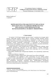
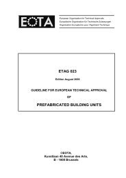
2.2 Use categories, products families, kits2.2.1 Claddings familiesFrom the mechanical design, Claddings are differentiated according to the methods of fixing.See below (figure A to H) some examples of families.Other exterior cladding kits may be assessed by appraisal of similarities with these families.<strong>ETAG</strong> <strong>034</strong>10
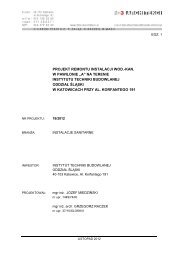
A- Cladding kit consisting of cladding elements mechanically fastened to the subframe by throughfixing (e.g. nails, screws, rivets, …) :B- Cladding kit consisting of cladding elements mechanically fastened to the subframe by a specificanchor placed in an undercut hole and anchored by mechanical interlock (at least 4 anchors)°:<strong>ETAG</strong> <strong>034</strong>11
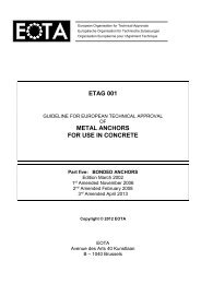
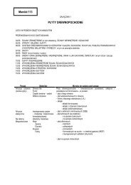
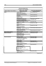
C- Cladding kit consisting of cladding elements installed on a horizontal grid of metal rails or pins(e.g. dowel anchor), screwed to a vertical subframeD- Cladding kit consisting of cladding elements, integrated with adjacent elements by interlockingtogether at top and bottom with an overlap, fixed to the subframe by mechanical fixings positionedon the top edge and masked by the edge of the upper elements<strong>ETAG</strong> <strong>034</strong>12
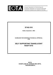
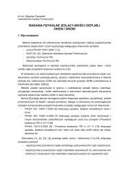
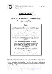
E- Cladding kit consisting of cladding elements fixed to the subframe by mechanical fixingspositioned on the top edge and masked by the edge of the upper plankF- Cladding kit consisting of cladding elements mechanically fastened to the subframe by at least 4metal clips or rails<strong>ETAG</strong> <strong>034</strong>13
G- Cladding consisting of elements suspended on the subframeH- Tile-hung Cladding kit<strong>ETAG</strong> <strong>034</strong>14
The following table gives examples of possible materials for the cladding elements and fixingsFAMILYEXAMPLES OFCLADDING ELEMENTMATERIALEXAMPLES OF FIXINGMATERIALAWood based, metal,stone, laminates, fibrecement or cementbonded particle boardsCorrosion protected steel,stainless steel oraluminium alloy in theform of nails, screws orrivetsBResin mortar, stone,ceramics, laminates orfibre-cement panelStainless steel anchorsCFibre reinforcedcement, resin mortar,stone, ceramics,laminates or fibrecement panelAluminium alloy profiles orstainless steel pinsDFibre reinforcedcement or plasticsCorrosion protected steel,stainless steel oraluminium alloy in theform of screwsEWood based, fibrecement, plastic orcement particle boardsCorrosion protected steel,stainless steel oraluminium alloy in theform of screws or nailsFFibre reinforcedcement, fibre cement,terra cotta or ceramictilesStainless steelG Metal cassette Stainless steel andaluminium alloy subframeHWood based panel,concrete, fibre cement,slate or terracotta tilesCorrosion protected steel,stainless steel, copper oraluminium alloy in theform of screws, nails orbrackets<strong>ETAG</strong> <strong>034</strong>15
2.2.2 Use categoriesSeveral use categories have been adopted to correspond to the degree of exposure to Impact in use(§ 6.4.4).2.3 AssumptionsThe state of the art does not enable the development, within a reasonable time, of full and detailedverification methods and corresponding technical criteria/guidance for acceptance for some particularaspects or products. This <strong>ETAG</strong> contains assumptions taking account of the state of the art andmakes provisions for appropriate, additional case by case approach when examining ETAapplications,within the general framework of the <strong>ETAG</strong> and under the CPD consensus procedurebetween EOTA members.The guidance remains valid for other cases which do not deviate significantly. The general approachof the <strong>ETAG</strong> remains valid but the provisions then need to be used case by case in an appropriateway. This use of the <strong>ETAG</strong> is the responsibility of the ETA-body which receives the special application,and subject to consensus within EOTA. Experience in this respect is collected, after endorsement inEOTA-TB Format – Comprehension document.General recommendationsThe content of an ETA deals with only: one family of cladding kit in accordance with the clause 2.2.1 (Fixing kit shall becompletely described) one cladding materialIn one ETA, there may be: several cladding dimensions (length, height, thickness) several cladding colours and surface textures several fixing types several fixing densities3 TERMINOLOGY3.1 Common terminology and abbreviations(See Annex A).3.2 Specific terminologyCLADDING KIT: A cladding kit is a specific kit made of an external cladding and defined fixingdevices which are normally, but not always, delivered together on site. The cladding is mechanicallyfixed to the wall using a subframe (see also EC Guidance Paper C).Other components according to Part II can be part of the kit.3.2.1 SubstrateThe term "substrate" refers to a wall, which in itself already meets the necessary airtightnessand mechanical strength requirements (resistance to static and dynamic loads), as well as watertightness and a relevant water vapour resistance.- Masonry wallsWalls constructed from units of clay, concrete, calcium silicate, autoclaved aerated concrete orstone laid using mortar and/or adhesive.- Concrete walls<strong>ETAG</strong> <strong>034</strong>16
Walls made of concrete either cast in situ or prefabricated at the factory.- Timber frameStructural members can be studs, joists and rafters made of solid wood or wood-basedmaterials.- Metal frameStructural members can be profiles made of steel or aluminium alloys materials.3.2.2 SubframeAn intermediate assembly of vertical and/or horizontal, wood or metal profiles, locatedbetween the cladding elements and the substrate.3.2.3 Cladding elementSheet, plank, tile, board, panel or cassette made of durable material applied at the externalface of a wall such as: wood based panels, fibre cement, concrete, stone, slate, ceramics,metal, plastics, laminates and brick slips.3.2.4 Cladding fixingProfiles, brackets, screws/anchors, nails, rivets or any special fixing devices used to secure thecladding element to the subframe.3.2.5 Subframe fixing devicesProfiles brackets, rivets/screws/anchors or any special fixing devices used to fasten thesubframe to the substrate and including:- fixings within the subframe- fixings of subframe to substrate3.2.6 Ancillary materialsAny supplementary element, component or product used in the kit, e.g. to form joints (sealant,corner strips, etc...) or to achieve continuity (mastic, joint-covers, gaskets, trims, etc...).3.2.7 Cavity barrier (compartmentation of air space)Element placed in the air space to separate horizontally or vertically two compartments of airspace (for fire or wind pressure purposes)<strong>ETAG</strong> <strong>034</strong>17
3.2.8 Air spaceSpace between the cladding and the insulation layer or substrate accordingly.3.2.9 Ventilated air spaceA layer of air between the substrate or insulation layer and cladding elements connected to theexternal environment permitting water vapour diffusion from the internal side of the wall.External wall claddings are considered as ventilated when the following criteria are fulfilled :• The distance between the cladding elements and the insulation layer or the substrateaccordingly (ventilation air space) amounts to at least 20 mm. This air space may bereduced locally to 5 to 10 mm depending on the cladding and the subframe, providedthat it is verified that it does not affect the draining and/or ventilation function,• Ventilation openings are envisaged, as a minimum, at the building base point and atthe roof edge with cross-sections of at least 50 cm 2 per linear metre.3.2.10 Breather membraneMembrane placed in the cladding kit which contributes to the watertightness of the wall.<strong>ETAG</strong> <strong>034</strong>18
Section two:GUIDANCE <strong>FOR</strong> THE ASSESSMENTOF THE FITNESS <strong>FOR</strong> USEGENERAL NOTES:a) Applicability of the <strong>ETAG</strong>This <strong>ETAG</strong> provides guidance on the assessment of Claddings and their intended uses. It is themanufacturer or producer who defines the cladding kits for which he is seeking an ETA and howthey are to be used in the works, and consequently the scale of the assessment.It is therefore possible that for some products, which are fairly conventional, only some of the testsand corresponding criteria are sufficient to establish fitness for use. In other cases, e.g. special orinnovative cladding kits or materials the whole package of tests and assessment may be applicableand even specific tests shall have to be added.b) General lay out of this sectionThe assessment of the fitness of products with regard to their fitness for intended use inconstruction works is a process with three main steps:- Chapter 4 clarifies the specific requirements for the works relevant to the products and usesconcerned, beginning with the Essential Requirements for works (CPD art. 11.2) and then listingthe corresponding relevant characteristics of products.- Chapter 5 extends the list in chapter 4 into more precise definitions and the methods available toverify product characteristics and to indicate how the requirements and the relevant productcharacteristics are described. This is done by test procedures, methods of calculation and ofproof, etc...- Chapter 6 provides guidance on the assessing and judging methods to confirm fitness for theintended use of the cladding kits.Chapter 7, assumptions and recommendations are only relevant in so far as they concern the basisupon which the assessment of the cladding kits is made concerning their fitness for the intendeduse.c) Levels or classes related to the essential requirements and to the productperformance (see ID clause 1.2 and EC Guidance paper E)According to the CPD "Classes" in this <strong>ETAG</strong> refer only to mandatory levels or classes laid down,in the EC-mandate.This <strong>ETAG</strong> indicates however the compulsory way of expressing relevant performancecharacteristics for the cladding kits. If, for some uses, at least one Member state has noregulations, a manufacturer always has the right to opt out of one or more of them, in which casethe ETA will state "no performance determined" against that aspect, except for those properties forwhich, when no determination has been made the product doesn’t any longer fall under the scopeof the <strong>ETAG</strong>.<strong>ETAG</strong> <strong>034</strong>19
d) Working life (durability) and serviceabilityThe provisions, test and assessment methods in this guideline or referred to, have been writtenbased upon the assumed intended working life of the cladding kits for the intended use of at least25 years, provided that the cladding kits is subject to appropriate use and maintenance (cf. chapter7). These provisions are based upon the current state of art and the available knowledge andexperience.An "assumed intended working life" means that it is expected that, when an assessment followingthe <strong>ETAG</strong>-provisions is made, and when this working life has elapsed, the real working life may be,in normal use conditions, considerably longer without major degradation affecting the essentialrequirements.The indications given as to the working life of cladding kits cannot be interpreted as a guaranteegiven by the producer or the approval body. They shall only be regarded as a means for thespecifiers to choose the appropriate criteria for cladding kits in relation to the expected,economically reasonable working life of the works (based upon ID. 5.2.2).e) Fitness for the intended useAccording to the CPD it has to be understood that, within the terms of this <strong>ETAG</strong>, products shall"have such characteristics that the works in which they are to be incorporated, assembled, appliedor installed, can, if properly designed and built, satisfy the Essential Requirements" (CPD, art. 2.1).Hence, the cladding kits shall be suitable for use in construction works which (as a whole and intheir separate parts) are fit for their intended use, account being taken of economy, and in order tosatisfy the essential requirements. Such requirements shall, subject to normal maintenance, besatisfied for an economically reasonable working life. The requirements generally concern actionswhich are foreseeable. (CPD Annex I - preamble).4 REQUIREMENTSCommon clause:This chapter sets out the aspects of performance to be examined in order to satisfy the relevantEssential Requirements, by:- Expressing in more details, for kits within the scope of the <strong>ETAG</strong>, the relevant EssentialRequirements of the CPD in the Interpretative Documents and in the mandate, for works orparts of the works, taking into account the actions to be considered, as well as the expecteddurability and serviceability of the works,- Applying them to kits within the scope of the <strong>ETAG</strong> (product and where appropriate itsconstituents, components and intended uses), and providing a list of relevant productcharacteristics and other applicable properties,- When a product characteristic is specific to one of the Essential Requirements it is dealt withunder that essential Requirement. If, however, the characteristic or property is relevant to morethan one Essential Requirement it, is addressed under the most relevant one with crossreference to the other(s). This is especially important where a manufacturer claims “Noperformance determined” for a characteristic under one Essential Requirement and it is criticalfor the assessing and judging under another Essential Requirement. Similarly, characteristicswhich have a bearing on durability assessment may be dealt with under ER 1 to ER 6 withreference under 4.7. Where there is a characteristic which only relates to durability this is dealtwith in 4.7.<strong>ETAG</strong> <strong>034</strong>20
This chapter also takes into account further requirements, (e.g. resulting from other ECDirectives) and identifies aspects of serviceability including specifying characteristics needed toidentify the products (cf. ETA-format § II.2).The following Table 1 presents an overview of the Essential Requirements, the relevantparagraphs of the corresponding Interpretative Documents and the related requirements toproduct performance.Table 1 - Relationship between ID paragraph for works, Cladding kit performance andproduct characteristic given in the mandateERCorrespondingID paragraphfor worksCorrespondingID paragraph forkit performanceMandateproductcharacteristic<strong>ETAG</strong> paragraphon kitperformance1 - - - -2 4.2.3.4Limitation of spread offire and smoke beyond4.3.1.1Products subject toreaction to fireReaction to fire4.2ER2:Safety in caseof firethe room of origin:Wallsrequirements:Facades / external walls4.2.3.4.2Façades/external wallsFire spread in cavitiesinside the façades,Fire resistance against:- Fire from the inside- Fire from the outside4.2ER2:Safety in caseof firealong the outsidesurface of the façadeand from one firecompartments33.3.1.2Indoor environment3.3.1.2.2Dampness controlWatertightness of jointsWater permeabilityWater vapourpermeability4.3.1ER3:IndoorenvironmentdampnessDrainability3.3.5outdoor environment3.3.5.3 :Release of pollutants tooutdoor air, soil andwaterContent and/or releaseof dangeroussubstances4.3.2Outdoorenvironment43.3.2 :Direct impactsImpacts of fallingobjects, forming part ofthe works, upon users3.3.2.2 :Performance of theworksResistance to wind loadMechanical resistanceof fixingResistance to horizontalpoint loadsImpact resistanceShatter properties4.4ER4:Safety in useResistance to seismicactionsHygrothermal behaviour5 4.2Protection againstairborne noise fromoutside of the works4.3.2Acoustic properties andtheir expressionacoustic performance ofthe kitAirborne soundinsulation4.5ER5:Protectionagainst noise6 4.2.3Expression of theenergy requirementsand their relation to the4.3.2Characteristics ofproducts which may berelevant to the essentialThermal resistance 4.6ER6:Energyeconomy and heatretention<strong>ETAG</strong> <strong>034</strong>21
products characteristicsrequirementAspects ofdurabilityandserviceabilityOther durability aspectsFatigueDimensional stabilityFreeze-thawchemicals and biologicalresistance4.7Aspect of durabilityand serviceabilitycorrosionUV radiation4.1 ER1: MECHANICAL RESISTANCE AND STABILITYRequirements with respect to the mechanical resistance and stability of non load bearing parts ofthe works are not included in this Essential Requirement but are treated under the EssentialRequirement Safety in use (see Clause 4.4).4.2 ER2: SAFETY IN CASE OF FIRE4.2.1 Reaction to fireThe reaction to fire performance of cladding kits shall be in accordance with laws, regulations andadministrative provisions applicable to the kit in its intended use application. This performanceshall be expressed in the form of a classification specified in accordance with the relevant ECDecision 96/603/EEC as amended and/or EN 13501-1 and/or an appropriate CWFT decision.4.2.2 Fire resistanceThe fire resistance requirement is applicable to the wall itself (made of masonry, concrete, timberor metal frame) and not on the cladding kits. The cladding kit alone does not meet any fireresistance requirements.The evaluation of "Fire propagation to upper levels" is not part of the European classification andthus, cannot be evaluated, i.e. to be omitted.4.3 ER3: HYGIENE, HEALTH AND ENVIRONMENT4.3.1 Indoor environment, dampnessAs far as dampness is concerned for external walls, two requirements have to be considered,for which Cladding kits have a favourable effect:- Moisture proofing from outside damp.External walls shall resist the penetration of rain and snow to the inside of the building; theyshall not be damaged by rain and snow and shall not carry moisture to any part where it couldcause damage.- Avoiding condensation on internal surfaces of the wall and interstitial condensation.Surface condensation is usually reduced by the application of cladding kits.Under normal conditions of use, harmful interstitial condensation does not occur in the kit.Where there is a high incidence of water vapour internally, appropriate precautions shall betaken to prevent the kit from becoming damp, for example by suitable design of the productsand choice of materials.<strong>ETAG</strong> <strong>034</strong>22
This means that for ER3 the protection against driving rain, water permeability (does not applyto kits with a ventilated air space), water vapour permeability (does not apply to kits with aventilated air space) and drainability characteristics have to be assessed for the kit and/oreach of its components.4.3.2 Outdoor environmentThe kit shall be such that, when installed according to the appropriate provisions of the MemberStates, it allows for the satisfaction of the ER3 of the CPD as expressed by the nationalprovisions of the Member States and in particular does not contaminate the outdoor environment(air, soil or water).• Used woodUsed wood are used products made from solid wood, wood based products or made fromlaminates, predominantly containing wood. In the case of wood-based panels ascladding: In some Member States there are special regulations for the use of usedwoods, which have to be met. Therefore the information if used wood is used for theproduction of wood-based panels has to be given.• BiocidesOnly such biocides may be applied which are approved according to CommissionDirective 98/8/EC of the European Parliament and of the Council. As long as the Annexesof the directive are not implemented, a declaration of the biocides, the amount and thestate of the treatment has to be given. Alternatively for wood preservatives a marking"PT"(treated with wood preservatives) according EN 13986 is possible.• Flame retardant/fire retardantA declaration of the flame/fire retardant, the amount and the state of the treatment has tobe given. A declaration, that no polybromated diphenylether are used, has to be given.• FormaldehydeIf formaldehyde-containing resins are used for the production of wood-based panels, therelease or the content of formaldehyde shall be determined.Note: In some Member States formaldehyde emitting products above class E1 (< 0,124mg/m³ in application of the measurement method foreseen in the relevant standard) areprohibited.• PentachlorophenolIf relevant, the content of pentachlorphenol shall be determined and declared.Note: In some Member States, kits/components which contain PCP are totally prohibitedor have a specific limit value.• Man made mineral fibresMan made mineral fibres, which are declared as cancerogenic of the EU category II shallnot be used.Asbestos is forbidden by European directive 76/769, and shall therefore not be used.• Ceramic fibresAlthough it is recommended that ceramic fibres should not be used, their presence doesnot prevent a kit from complying with the provisions of this <strong>ETAG</strong>, as long as this isconsistent with regulatory requirements in the Member State of use.CadmiumThe content of cadmium and cadmium compounds contained in plastics, paints, lacquers,varnishes, zinc or zinc coatings and used as a coating shall meet the respectiveregulations.4.4 ER4: SAFETY IN USEEven though Cladding is a kit without a structural intended use, mechanical resistance andstability is still required.<strong>ETAG</strong> <strong>034</strong>23
The installed kits shall be stable to the combined stresses generated by normal loads such asintrinsic weight, temperature, humidity and shrinkage, as well as movements of the substrate,direct impacts and wind forces (pressure and suction).This means that for ER 4, the following products characteristics have to be assessed for the kitand/or its components:Effect of intrinsic weightThe kit shall support itself without harmful deformation.Impact resistanceThe kit shall be designed so that it retains its properties under the effect of impacts caused bynormal traffic and normal use. Its performance shall be such that the effect of normal accidentalor deliberately caused unexceptional impact does not cause damage which results in injury topersons e.g. dangerous cutting edges or the falling of objects forming part of the works uponusers. Damage caused by impacts shall not result in the kit failing to continue to satisfy any of theother relevant Essential Requirements, e.g. damage resulting in water penetration compromisingER 3.Shatter propertiesCladding products shall not, in the event of breakage, present sharp or cutting edges. Theirsurface shall not cause bodily injury, either for the occupants or for people nearby.Horizontal point loadsUnless the manufacturer, in his installation and maintenance information, specifically excludes it,it shall be possible to lean standard maintenance equipment against the kit, without causingdamage which results in injury to persons e.g. dangerous cutting edges or the falling of objectsforming part of the works upon users or which results in the kit failing to continue to satisfy any ofthe other relevant Essential Requirements, e.g. damage resulting in water penetrationcompromising ER 3.Effect of the wind actionThe kit shall exhibit appropriate mechanical resistance to the forces of pressure, suction andvibration, due to wind.Effect of seismic actionsWhen applicable, relevant Eurocodes, European and/or national regulations shall be taken intoaccount.Behaviour under hygrothermal variationsThe external cladding shall withstand movements due to humidity and temperature variationsexcept at structural joins where special precautions have to be taken.<strong>ETAG</strong> <strong>034</strong>24
4.5 ER5: PROTECTION AGAINST NOISENot relevant to Part I.4.6 ER6: ENERGY ECONOMY AND HEAT RETENTIONNot relevant to Part I.4.7 ASPECTS OF DURABILITY AND SERVICEABILITYAll of the ER’s mentioned above shall be fulfilled for the life of the kit under the actions to which itis subjected.Kit durabilityThe cladding kits shall be stable to temperature variation, humidity, shrinkage and/or swelling,freeze-thaw cycles, chemical and biological attacks, corrosion and UV radiation.Performance on exposure to movements of the substrateNormal movements of the substrate shall not give rise to any crack formation in the kit. Thecladding kits shall withstand movements due to the temperature and stress variations except atstructural joints where special precautions have to be taken.Neither high nor low temperatures shall exercise a destructive or irreversibly deforming effect.Low air temperatures of the order of - 20°C and high air temperatures of + 50°C are generallyregarded as the extremes in temperature change. In northern European countries however, thetemperatures of the air can decrease to - 40°C.Solar radiation increases the surface temperatures of the cladding kits when exposed. Theincrease depends on the radiation flow and the energy absorption of the surface (colour). It isgenerally considered that the maximum surface temperature is + 80°C (e.g. for opaque claddingelements).A change (of the order of 50°C) in the surface temperature shall not cause any damage, e.g. asudden change due to prolonged exposure to solar radiation followed by intensive rain, or thechange of temperature between sun and shade.In addition, steps shall be taken to prevent crack formation both at the expansion joints of theworks and where elements of the wall are of different materials, e.g. connections to windows.Durability of componentsAll components shall retain their properties during the overall service life of the kit under normalconditions of use and maintenance such that the kit conformity is maintained. This requires thefollowing:- All components shall display chemical-physical stability.- All materials shall be either naturally resistant to, or be treated or protected against attack bycorrosion, fungus or UV radiation.- All materials shall be compatible with each other.- Components possibly susceptible to moisture penetration shall be subject to axial tension testsafter water immersion.<strong>ETAG</strong> <strong>034</strong>25
5. METHODS OF VERIFICATIONThis chapter refers to the verification methods used to determine the various aspects ofperformance of the products in relation to the requirements for the works (calculations, tests,engineering knowledge, site experience, etc...). The possibility exists to use existing data inaccordance with the EOTA Guidance Document 004 on the “Provision of data for assessmentleading to ETA”.Depending on the design of the kit, the approval body shall determine the assessment program(tests, calculation...) and in particular the relevance of the tests listed here after.In order to assess and judge Claddings it is often necessary to adopt verification methods whichrequire the testing of two or more components in a small scale assembly. As such, they are neitherkits nor components. By taking this approach, it is possible to either avoid a large number of fullscale tests or at least limit the number required, by enabling the selection of the appropriatecombination of components to provide an assessment of the complete range.Therefore, the structure of this chapter is that these tests relate to the kit rather than to theindividual components.In any test report, the tested products shall be described with information about material, geometry,subframe and fixing method.The relevant Essential Requirements, the relevant verification methods related to the essentialrequirements and the related product characteristics to be assessed are indicated in the followingTable 2.<strong>ETAG</strong> <strong>034</strong>26
Table 2 – Verification of performanceER<strong>ETAG</strong> Paragraph onproduct performanceProduct characteristic <strong>ETAG</strong> paragraph on verification methodKitComponent1 - - - -2 4.2Safety in case of fire Reaction to fire5.2.1 and 5.2.2Reaction to fire34.3.1Indoor environment,dampness4.3.2outdoor environmentFire resistanceWatertightness of jointsWater permeabilityWater vapourpermeabilityDrainabilityContent and/or release ofdangerous substances5.2.3Fire resistance5.3.1Watertightness of joints(protection against drivingrain)5.3.2Water permeability ofcladding element(resistance to waterdiffusion)5.3.4Drainability5.3.5Content and/or releasedangerous substances5.3.3Water vapourpermeability5.3.5 Content and/orrelease of dangeroussubstances4 4.4Safety in useWind load resistance5.4.1.1Wind suction testMechanical resistance offixingResistance to horizontalpoint loadsResistance to impact -Shatter propertiesResistance to seismicactions5.4.1.2Wind pressure test5.4.2Mechanical test5.4.3Resistance to horizontalpoint loads5.4.4Impact resistance5.4.5Resistance to seismicactions5.4.6Hygrothermal behaviour Hygothermal behaviour5 4.5Protection against noise Airborne sound insulation 5.5ER5 Protection againstnoise6 4.6Energy economy andheat retentionThermal resistance 5.6ER6 Energy economy andheat retention--<strong>ETAG</strong> <strong>034</strong>27
Aspects ofdurabilityandserviceability4.7Aspects of durability andserviceabilityFatigueDimensional stabilityFreeze-thawchemicals and biologicalresistanceCorrosionUV radiation5.7.1Pulsating load5.7.2Dimensional stability ofexternal cladding5.7.3Immersion in water5.7.4Freeze-thaw5.7.5Chemical and biologicalresistance5.7.6Corrosion5.7.7UV radiation55.1 ER1: Mechanical resistance and stabilityThis requirement is not relevant to cladding kits (see ER4 Safety in Use).5.2 ER2: Safety in case of fire5.2.1 Reaction to fire in intended usedExcept where the reaction to fire performance of the kit can be known, the cladding kit and itscomponents shall be tested, using the tests methods relevant for the corresponding reaction tofire class, in order to be classified according to EN 13501-1: 2007.Where all components of the kit are class A1 without testing according to Decision96/603/EEC as amended, the whole kit may be classified Class A1 without testing. Where oneor more of the components is classified according to a CWFT Decision, the whole kit may beclassified to the lowest class of any component.The potential contribution of a product to a fire does not only depend on its intrinsic propertiesand the thermal attack, but also to a large extent on its end-use situation when incorporated inthe works. Tests shall be conducted therefore to simulate its end-use situation.The reaction to fire classification and relevant testing shall be given for the entire kit, e.g. if thecladding is intended used to be applied with thermal insulation behind, it shall be tested withthis insulation.EN 13823 gives only a general description of the arrangement of the test specimen. UnlessEuropean Standard exists (e.g. EN 438-7), Annex E includes precise, specific informationabout the SBI-Testing for cladding kits.For the time being, performing assessments according to the reaction to fire tests are judgedsufficient in some countries for the determination of the behaviour in fire of the cladding kits; inMember States where regulatory requirements demand full-scale façade testing, such testingshall be performed according to national provisions (no European method currently existing).Such testing does not form part of the ETA assessment.<strong>ETAG</strong> <strong>034</strong>28
5.2.2 Reaction to fire on back sideAsymmetrically composed cladding elements may have to be tested and classified accordingto the provisions of EN 13501-1:2007. When tested the SBI test (EN 13823), the test shallinvolve a free-hanging arrangement with the flame impingement to the rear side in accordancewith EN 13823 (test arrangement without open joints between the cladding elements andwithout insulation layer on A1 or A2 substrate, so that the distance between the substrate andthe cladding elements amounts to at least 80 mm).5.2.3 Fire resistanceNot relevant.5.3 ER3 : Hygiene, health and the environment5.3.1 Watertightness of joints (protection against driving rain)Cladding kits contribute to the watertightness of the wall. The degree of watertightness of acladding kit is generally assessed by appraisal of design, taking account of the characteristicsof the materials used and the geometry of external cladding element and joints.Open joints are not watertight.If joints are not watertight, the insulation layer shall be made of EPS to EN13163, XPS to EN13164, PUR to EN 13165, phenolic foam to EN 13166 or mineral wool to EN 13162 (WS orWL(P), depending on the national regulations).If watertightness of closed joints is needed, an artificial rain test shall be carried out on thecladding kit in accordance with EN 12865 Procedure A (600 Pa maximum). A translucentpanel (PMMA thickness 8 mm) with 3 mm diameter holes (0,01 % holes) is placed behind thecladding (Figure 2 and Figure 3).For example, if the size of sample is 2 400 x 1 200 mm, the display of holes can be madeaccording to Figure 1.<strong>ETAG</strong> <strong>034</strong>29
Figure 1 – Example of distances between holesCLADDINGFIXINGSJOINTPROFILESPressure PressionFigure 2 - Example of test device – vertical section<strong>ETAG</strong> <strong>034</strong>30
Pression PressureCLADDINGJOINTFigure 3 - Example of test device – horizontal section5.3.2 Water permeability of cladding element (resistance to water diffusion)The test is not relevant due to the fact that only kits designed with ventilated air space areconsidered in this part.5.3.3 Water vapour permeabilityThe test is not relevant due to the fact that only kits designed with ventilated air space areconsidered in this part.5.3.4 DrainabilityThe drainability of a cladding kit is generally assessed by appraisal of design taking into accountof the characteristics of materials used and geometry of external cladding and joints.The cladding kit shall be designed and installed so that water which penetrates in the air spaceor condensation water shall be drained out of the installed kit without accumulation or moisturedamage or leakage into the substrate or the wall cladding kit.<strong>ETAG</strong> <strong>034</strong>31
5.3.5 Content and/or release of dangerous substances5.3.5.1 Content and/or release of dangerous substances in the productThe applicant shall submit a written declaration stating whether or not the product/kitcontains dangerous substances according to European and national regulations, when andwhere relevant in the Member States of destination, and shall list these substances.Used woodIn case of wood-based panels as cladding element, the use of used wood for the productionof cladding elements has to be declared by the applicant.BiocidesThe use of biocide(s) has to be declared by the applicant stating the trade name(s) of thebiocide(s), the chemical name(s) of the active component(s), the amount(s) and the technicalprocedure of application. Alternatively for wood preservatives a marking “PT” (treated withwood preservatives) according to EN 13986 is possible.Flame retardant/fire retardantThe use of flame/fire retardant(s) has to be declared by the applicant stating the tradename(s) of the flame/fire retardant(s), the chemical name(s) of the active component(s), theamount(s) and the technical procedure of application. A declaration, that no polybromateddiphenylether is used, has to be given.Note: CEN TC 351 is harmonizing test methods for polybrominated and therein containedpolyhalogenated dibenzodioxines and polyhalogenated dibenzofuranes. Therefore theverification is provisionally, because harmonized European provisions are missing. ComingEuropean provisions could request other verification methods.FormaldehydeIf formaldehyde containing resins are used for the production of wood based panels, theassessment of the release or the content of formaldehyde shall be performed according toEN 13986; for laminates it shall be performed according to EN 438-7.PentachlorophenolIf relevant, the content of pentachlorophenol shall be determined according to CEN/TR14823 or shall be performed in accordance with a test procedure that reflects the state of theart.Note: CEN TC 351 is harmonizing test methods for PCP. Therefore the verification isprovisionally, because harmonized European provisions are missing. Coming Europeanprovisions could request other verification methods.Man made mineral fibresMan made mineral fibres shall only be used if they fulfil one of the conditions of the method Ior method II.Method IProof that a suitable intraperitoneal test did not express signs of excessive carcinogenicity.The half life of intratracheal instillation of a 2 mg fibre - suspension for fibres longer than 5<strong>ETAG</strong> <strong>034</strong>32
µm, a diameter less than 3 µm and a relation of length to diameter greater than 3:1 (WHO-Fasern) does not exceed 40 days.The "Kanzerogenitätsindex KI", resulting from the difference between the sum of the masscontents (in %) of the oxides of sodium, potassium, boron, calcium, Magnesium, barium andthe double mass content (in %) of alumina results, shall be at least 40.Method IIThe product has to meet the requirements given in comment Q and R of the Directive97/69/EC.Note 1: For some Member States, method I is mandatory.Note 2: CEN TC 351 is harmonizing test methods for man-made vitreous (silicate) fibres withrandom orientation with alkaline oxide and alkali earth oxide content greater than 18% byweight.. Therefore the verification is provisionally, because harmonized European provisionsare missing. Coming European provisions could request other verification methods.Ceramic fibresIf appropriate, the use of ceramic fibres shall be declared by the applicant.Note 1: Ceramic fibres should be substituted.Note 2: If the applicant can show sufficiently, that there are no alternative products on themarket available to achieve the technical behaviour of insulation material, the approval bodycan decide to approve the product/kit anyway, subject to any regulatory requirements on theuse of ceramic fibres being met.CadmiumThe content of cadmium contained in plastics, paints, lacquers, varnishes, zinc or zinccoatings shall be determined. If cadmium or a cadmium compound is used as a coating, thisshall be declared by the applicant.Note: CEN TC 351 is harmonizing test methods for cadmium or cadmium compounds.Therefore the verification is provisionally, because harmonized European provisions aremissing. Coming European provisions could request other verification methods.5.3.5.2 Compliance with the applicable regulationsIf the product/kit contains dangerous substances as declared above, the ETA will provide themethod(s) which has been used for demonstrating compliance with the applicableregulations in the Member States of destination, according to the EU data-basehttp://ec.europa.eu/enterprise/construction/cpd-ds/index.cfm (method(s) of content or release, asappropriate).5.3.5.3 Application of the precautionary principleAn EOTA member has the possibility to provide to the other members, through the SecretaryGeneral, warning about substances which, according to Health authorities of its country, are<strong>ETAG</strong> <strong>034</strong>33
considered to be dangerous under sound scientific evidence, but are not yet regulated.Complete references about this evidence will be provided.This information once agreed upon, will be kept in an EOTA data base, and will betransferred to the Commission services.The information contained in this EOTA data base will also be communicated to any ETAapplicant.On the basis of this information, a protocol of assessment of the product, regarding thissubstance, could be established on request of a manufacturer with the participation of theApproval Body which raised the issue.5.4 ER4 : Safety in useA control of the mechanical properties of the products used for the tests has to be performed.If the test results according to 5.4.2 are better than the mechanical properties to be declared inthe ETA,an appropriate reduction of the test results according to 5.4.1, proportional to thecharacteristic value of thickness and the characteristic value of modulus of elasticity or rupturestrength is necessary (e.g. for thickness : ratio of cubic value).5.4.1 Wind load resistanceBoth the tolerance due to manufacturing and/or installation and deformations due totemperature and humidity variations have to be taken into account and the most critical caseshall be tested. The most critical case shall be explained.One test specimen for each chosen geometry is performed. If the test result obtained does notconfirm the results obtained by mechanical tests in accordance with §5.4.2, at least two othertest specimen have to be tested.5.4.1.1 Wind suction testThe principle is to reproduce the effects of suction on the cladding kit.The number of tests depends on the combination of parameters presented for the kit approval.As a minimum, the weakest design mechanically is tested.Preparation of the test specimenThe test specimen shall be mounted in the test rig in accordance with the manufacturer’sinstructions.The test specimen comprises:- a non airtight substrate (test rig) such as wood or steel rigid frame or masonry or concretewall with one hole per square metre, with a diameter at least 15 mm.- the cladding secured with the specified fixing devices for the kit (adapted to the frame)- The dimensions of the test specimen depend on the size of external cladding element andthe specified fixing devices :<strong>ETAG</strong> <strong>034</strong>34
* for cladding elements which are mechanically fixed independent of each other (i.e. CaseA, B, F or G), a minimum surface cladding of 1,5 m 2 shall be tested.* If they depend on each other vertically and horizontally (i.e. Case D or H), at least 3 x 3elements shall be tested.* If they depend on each other vertically or horizontally (i.e. Case C or E), at least 4elements shall be tested.The air permeability of the test specimen can be reduced provided no interference withmechanical resistance of the test specimen occurs.Test equipmentThe test equipment consists of a pressure or suction chamber against which is placed the testrig. The depth of chamber shall be sufficient for a constant pressure or suction to be exertedon the test specimen (applied to the front surface of external cladding element) irrespective ofits possible deformation. The chamber is mounted on a rigid frame. The cladding serves asthe seal between the chamber and the environment. The connection between the claddingelement and the chamber shall be sufficient to allow a realistic deformation of the test kit underthe influence of simulated wind suction.Test procedureThe uniformly distributed loads are exerted on the front face of external cladding elements.The test is performed in successive steps (two steps of 300 Pa, one step to 500 Pa and thenone step of 1000 Pa, then steps of 200 Pa thereafter, with a return to between zero and 300Pa after each step), until significant irreversible deformation (deformation which affect thefitness for use) or failure occurs (see figure 5).At each level, the load is maintained constant for at least 10 s, after stabilization of claddingdeformations.The test is then continued until failure occurs.The deflection shall be measured, if appropriate, at the cladding element and on the fixing as afunction of reduced pressure and reported in tabular or graphic form.With the differential pressure reduced to zero, the permanent deflection shall be noted after 1minute recovery. The reduced pressure at which defect or damage occurred shall be noted.The pins fixing the cladding to the test slab shall not constitute weak points and shall thereforebe chosen accordingly.Observations during the testFailure is defined by any one of the following events:1. Any cladding elements breaks,2. Any cladding element presents a significant permanent deflection,3. The failure of fixings,4. The failure or detachment of the frame.Test results<strong>ETAG</strong> <strong>034</strong>35
The test result is°:- the load Q for which the test specimen fails (Take the last pressure)- the type of failure- the value of deflection as a function of the load given in graphic formThe test results are only valid for those fixing patterns tested.Test specimen descriptionIt is necessary to describe the test specimen by giving details about:- External cladding elements: geometry and dimensions- Fixing system- Fixing density- Subframe (material properties, section, distance between the supports).<strong>ETAG</strong> <strong>034</strong>36
Data logger measures valueSKINFIXINGSOPENED JOINTRAILSSuctionControlled and meteredair supply generatingpositive and negative pressuresAir flowmeasurement deviceFigure 4 - Example of wind pressure and suction apparatusFigure 5 - Example of wind load design<strong>ETAG</strong> <strong>034</strong>37
Alternative test methodThe alternative test may be used for all product families, provided that the geometric shapeallows the foil bags to be placed in the air space and be blown out so that a uniformlydistributed pressure load at the rear face of the cladding is possible (e.g. for families E, G andH, this method is not recommended).Preparation of the test specimenThe test specimen shall be mounted such as defined in the last test.Test equipmentThe test rig consists of a rigid frame (steel construction) made of vertical longitudinal girderand horizontal profiles (e.g. anchor channel) and rigid boards or a massive wall such asmasonry or concrete.The subframe of the cladding kit has to be fixed on the rig and the cladding elements have tobe fixed on the subframe according to the indications given by the ETA applicant.The vertical profiles of the rig can be movable (sliding) so that they can be placed in the axis ofthe fixings of the cladding.Foil bags which are placed in the air space at the rear side of the cladding are blown out andthey exert a uniformly distributed pressure load on the rear face of the cladding whichcorresponds to the wind suction load.Test procedureTwo pressure pulses between zero and 300 Pa shall be applied.The test is performed in successive steps of 500 Pa up to 1000 Pa and 200 Pa after 1000 Pa,with a return to zero at each level, until significant irreversible deformation occurs (see Figure5). At each level, the load is maintained constant for ca. 10 seconds after stabilization of thecladding deformations and the displacements are measured.The test is then continued until failure occurs.The deflection shall be measured at the cladding element and on the fixing as a function of theload and reported in tabular or graphic form.The failure load for which there is a defect or damage in the kit shall be noted.When the surface on which the load is applied is different from the whole surface of the testedcladding for construction reasons, the failure load reached during the test has to be correctedand reduced by calculation considering the surface on which the load is applied in relation tothe whole surface of the tested cladding. The failure load given in the test report shall alwaysrefer to the whole surface.The fixings of the subframe to the test rig shall not constitute weak points and shall thereforebe chosen accordingly.<strong>ETAG</strong> <strong>034</strong>38
Observations during the testFailure is defined by any one of the following events :• Any cladding elements breaks,• Any cladding element presents a permanent deflection.• The failure of fixings.• The failure or detachment of the frame.Test resultsThe test result is°:- the load Q for which the test specimen fails (Take the last pressure)- the type of failure- the value of deflection as a function of the loadThe test results are only valid for those fixing patterns tested.Test specimen descriptionIt is necessary to describe the test specimen by giving details about:- External cladding element: geometry and dimensions- Fixing system- Fixing density- Subframe (material properties, section, distance between the supports).5.4.1.2 Wind pressure testIn cases where for the resistance to wind pressure may be lower than the resistance to windsuction, supplementary tests with a wind pressure load have to be performed. Otherwise thewind pressure is equal to the wind suction resistance.The test procedure is similar to § 5.4.1.1, only the wind action is reversed.5.4.2 Mechanical testFor all cladding families, the bending strength, modulus of elasticity and rupture of the product,determined according to Annex C is required.The material and geometric properties of the fixings are to be declared according to eitherrelevant EN standard or <strong>ETAG</strong>. Otherwise the pull-out resistance has to be determined bytesting.The fasteners shall be installed in accordance with the manufacturer’s installation instructions.Both the tolerance due to manufacturing and/or installation and dimensional variations due totemperature and humidity variations have to be taken into account and the most critical caseshall be tested.Depending on the family and the materials used and on the design of the kit, the mechanicalresistance of the fixings has to be tested in ambient conditions (reference tests) and also, ifrelevant, after the effects due to sustained loading.The tests shall be carried out on the envisaged cladding material to be fixed.<strong>ETAG</strong> <strong>034</strong>39
The material used for the tests shall be specified in detail.5.4.2.1 Family A5.4.2.1.1 Pull-through resistance of cladding elementTesting of pull-through resistance of the panel is carried out in accordance with the followingtest procedure.The test is performed in ambient conditions, until failure by pulling through.Samples with a fixing driven through the centre, corner and middle of each sample are appliedas show in Figure 6 and Figure 7.The size of samples shall be given in function of supporting ring diameter.The test series shall be evaluated separately on 3 rings between 50 and 350 mm. For fibrecementand laminates panels, 180, 270 and 350 mm are recommended.An axial tension load is exerted on the fixing. The speed rate shall be adjusted to 5 mm/min.The force can be applied either by pushing on the head of the anchor or pulling the end of theanchor.Figure 6 - Example of test on fixing in corner<strong>ETAG</strong> <strong>034</strong>40
Figure 7 - Example of test on fixing in edge and centreFor each implantation (centre, middle and corner) and each ring, at least 5 tests shall becarried out.The results are expressed in N.The test report shall detail the following in accordance with Annex D:- Each F I , value- The mean F I , value- The characteristic F I C value giving 75 % confidence that 95 % of the test results will behigher than this value- The mode of failure description.<strong>ETAG</strong> <strong>034</strong>41
5.4.2.1.2 Pull-through resistance under shear loadsSample strips are mechanically fixed to a wooden batten or a metal profile with one fixing.On specimens of the cladding and substructure at least 5 shear tests each according to Figure8 shall be carried out.When testing, the edge distances a min and b min (accord. to figure 8) shall be conform tothe smallest edge distances intended to be used for the cladding kit.On the test specimens with the lowest ultimate loads the number of tests shall besupplemented so that for a statistical evaluation at least 7 test results are available.For fixings of parts of the exterior wall cladding which have nearly the same stiffness, the testsshall be performed according to Figure 8.c).If a part is almost rigid in comparison with the other, the tests shall be performed according toFigure 8.d).If the relative stiffnesses are between those requiring tests to Figure 8.c) and 4.d), then bothtests shall be carried out.The speed rate shall be adjusted to 5 mm/min.a) view b) viewF Q : shear forcea min : smallest intended edgedistance of the claddingb min : smallest intended edgedistance of the subframes 1 : thickness of the claddings 2 : thickness of thesubframec) section, case 1 d) section, case 2Figure 8 - Examples of shear load test<strong>ETAG</strong> <strong>034</strong>42
The failure load in N and the deformation at failure is measured.The test report shall detail the following in accordance with Annex D:- Each F S , value- The mean F S , value- The characteristic F S C value giving 75 % confidence that 95 % of the test results will behigher than this value- the measured deformation at failure- The mode of failure description.5.4.2.2 Family BFor the tests to be performed, every façade panel is fixed with at least four special anchorsplaced in a rectangular pattern.The failure load in N and the deformation at failure is measured.The test report shall detail the following in accordance with Annex D:- Each F B , value- The mean F B , value- The characteristic F B C value giving 75 % confidence that 95 % of the test results will behigher than this value- The mode of failure description.5.4.2.2.1 Axial tension test with varying diameter of supportThe tests shall be carried out under normal environmental conditions on panel sections withsingle anchors without edge and spacing effects.The diameter of the supporting ring shall be changed (for example between Ø 50 and 350mm) in order to find out the diameter d ref where the failure mode changes from pull-out of thefixing element or cone failure to bending failure of the test specimen (Figure 9).The test series shall be evaluated separately for each diameter. For each test series at least 5tests shall be performed.Figure 9 – Example of test of fixing<strong>ETAG</strong> <strong>034</strong>43
5.4.2.2.2 Shear testThe tests shall be carried out under normal environmental conditions on panel sections withsingle anchors without edge and spacing effects.The special anchor shall be installed as specified by the applicant. The shear load shall beapplied on the fixing without eccentricity and without exposure to moments (Figure 10).Figure 10 - Example of test of fixingThe loading speed shall be adjusted so that the failure occurs in 1 minute +/- 30 seconds.Per test series at least 5 tests shall be performed.5.4.2.2.3 Tests with combined tension and shear loadingThe tests shall be carried out under normal environmental conditions on panel sections withsingle anchors without edge and spacing effects.The special anchor shall be installed as specified by the applicant.The direction of load shall correspond to an angle of 30° and 60° relative to the plane of thepanel (Figure 11).The diameter of the supporting ring shall be changed (for example between Ø 50 and 350mm) in order to find out the diameter d ref where the failure mode changes from pull-out of thefixing element or cone failure to bending failure of the test specimenPer test series at least 5 tests shall be performed.<strong>ETAG</strong> <strong>034</strong>44
5.4.2.3 Family CFigure 11 - Example of test of fixing5.4.2.3.1 Resistance of grooved cladding elementThe test is performed in ambient conditions.Samples with a fitting are applied to a rigid substrate as show in Figure 12.A force is exerted, at a speed rate of 5 mm/min on the profile. The force is applied by pullingthe head of the profile. If brackets are used (instead of profile), then the length (L) of thebrackets may be < 100 mm.<strong>ETAG</strong> <strong>034</strong>45
a and b depend on kit, material, fabrication tolerancesFigure 12 - Example of test of fixingA minimum of 5 tests shall be carried out.The results are expressed in N.The test report shall detail the following in accordance with Annex D:- Each F f , value- The mean F f , value- The characteristic F fC value giving 75 % confidence that 95 % of the test results will be higherthan this value- The mode of failure description.5.4.2.3.2 Resistance of stone at the dowel holeDetermination of the resistance shall be in accordance with the standard EN 13364.5.4.2.3.3 Resistance to vertical loadThis test is performed in ambient conditions.The cladding kit is fixed to the wall, in accordance with the manufacturer’s instructions.<strong>ETAG</strong> <strong>034</strong>46
The deflection of the profile shall be measured.One cladding element is installed on the profile and an additional dead load equivalent to twocladding elements is added, on top of the first one.The test can be stopped if the deflection is less than 0.1 mm after 1 hour.The test result is a deflection curve as a function of the time and the maximum deflection.5.4.2.3.4 Pull-through resistance of fixings from profilesThis test establishes the pull-through resistance of an anchor through the perforation in theprofile.The test is carried out on at least 5 samples each measuring 300 mm ± 20 mm and perforatedin the centre, using a drilled hole.The apparatus consists of:- A dynamometer,- A support and metal screw as shown in Figure 13.Figure 13 - Example of testThe samples are conditioned for at least 2 h at (23 ± 2) °C before the test.The screw is placed perpendicular to the profile as described in Figure 13.The test is carried out at (23 ± 2) °C using a tensioning speed of 20 mm/min.The pull-through resistance is expressed in N.The test report shall detail the following in accordance with Annex D:- Each R S , value- The mean R S , value- The characteristic R SC value giving 75 % confidence that 95 % of the test results will behigher than this value- The mode of failure description.5.4.2.4 Family D5.4.2.4.1 Pull-through resistance of cladding elementThe test is performed in ambient conditions.Samples, length 200 mm at least, with a fixing are applied to a supporting ring as show inFigure 14. The diameter depends on the material of the sample. It shall be about 50 mm.<strong>ETAG</strong> <strong>034</strong>47
Figure 14 - Example of test of fixingA force is exerted, at a speed rate of 10 mm/min on the anchor through the cladding elementuntil failure. The force can be applied either by pushing on the head of the anchor or pullingthe end of the anchor.A minimum of 5 tests shall be carried out.The results are expressed in N.The test report shall detail the following in accordance with Annex D:- Each F S , value- The mean F S , value- The characteristic F SC value giving 75 % confidence that 95 % of the test results will behigher than this value- The mode of failure description.5.4.2.4.2 Resistance of grooved cladding elementThis requirement is considered in the paragraph 5.4.2.3.1.5.4.2.4.3 Pull-through resistance under shear loadsThis requirement is considered in the paragraph 5.4.2.1.2.5.4.2.5 Family E5.4.2.5.1 Pull-through resistance of cladding elementThis requirement is considered in the paragraph 5.4.2.4.1.5.4.2.5.2 Pull-through resistance under shear loadsThis requirement is considered in the paragraph 5.4.2.1.2.<strong>ETAG</strong> <strong>034</strong>48
5.4.2.6 Family F5.4.2.6.1 Resistance of metal clipThe test is performed in ambient conditions.Metal clips are applied to a rigid substrate as show in Figure 15.A force is exerted, at a speed rate of 5 mm/min on the metal clip.Figure 15 - Example of test of metal clipThe test is performed in successive steps with a return to zero at each level, until 1 mmirreversible deformation occurs.The test is then continued until failure occurs.The deflection shall be measured and reported in tabular or graphic form.At least 5 tests shall be carried out.The results are expressed in N.The test report shall detail the following in accordance with Annex D:- Each F mc value for 1 mm irreversible deformation- The mean F mcs value- The characteristic F mcSC value giving 75 % confidence that 95 % of the test results will behigher than this value- The mode of failure description5.4.2.6.2 Resistance to vertical loadThis test is performed in ambient conditions.The cladding kit is fixed to the wall, in accordance with the manufacturer’s instructions whichspecify also the type of wall.The deflection of the profile shall be measured.One cladding element is installed on the profile and an additional dead load equivalent to twocladding elements is added, on top of the first one.The test can be stopped if the deflection is less than 0.1 mm after 1 hour.The test result is a deflection curve as a function of the time and the maximum deflection.<strong>ETAG</strong> <strong>034</strong>49
5.4.2.7 Family G5.4.2.7.1 Resistance of slotThe test is performed in ambient conditions.Samples with notch are applied to a rigid substrate as show in Figure 16.A force is exerted, at a speed rate of 5 mm/min on the cladding element’s fixing until failure.Figure 16 - Example of slot testA minimum of 5 tests shall be carried out.The results are expressed in N.The test report shall detail the following in accordance with Annex D:- Each F n value- The mean F ns value- The characteristic F nsc value giving 75 % confidence that 95 % of the test results will behigher than this value- The mode of failure descriptionNote : In case of a doubt on a resistance of dead load or in case of anti-lift up, a test in thevertical direction of the cassette may be performed.5.4.2.8 Family HIf the cladding elements are fixed by nails or screws, the through cladding element test inaccording with § 5.4.2.4.1 and pull-through resistance under shear loads tests in accordingwith § 5.4.2.1.2 are performed.If the cladding elements are fixed by metal clip, the test in according with § 5.4.2.6 isperformed.5.4.3 Resistance to horizontal point loadsWhere required, the behaviour when tested for horizontal static load in service (ladder bearingagainst it) shall be checked.<strong>ETAG</strong> <strong>034</strong>50
The cladding kit shall be capable of accommodating the horizontally applied loads acting on itssurface arising from maintenance without any reduction in its performances.The cladding shall sustain safely, without reduction in performance and without permanentdeformation to any component, a static 500 N load applied one minute horizontally throughtwo squares of 25 x 25 x 5 mm spaced apart (distance 440 mm) on any part of the surface ofthe cladding (one person standing on a ladder leaning against the surface of the cladding) atroom temperature.5.4.4 Impact resistanceThe verification method proposed in this <strong>ETAG</strong> is similar to the EOTA Technical Report TR001– <strong>Edition</strong> February 2003.5.4.4.1 Resistance to hard body impactHard body impact tests are performed as described in ISO 7892: 1988. The points of impactare selected taking into account various modes of behaviour of walls and their cladding,varying according to whether the impact point is or is not located in an area of greater rigidity(At less than 50 mm from the edge of cladding element).Hard body impacts (10 Joules) are carried out with the steel ball weighing 1 kg and from aheight of 1.02 m (At least three locations).Hard body impacts (1 to 3 Joules) are carried out with the steel ball weighing 0.500 kg andfrom a height of 0.20 to 0.61 m (At least three locations).Observations:The presence of any micro cracks or cracks, at the impact point and at the circumference, isnoted. The area of the cracked zone is measured and noted. The nature of any breakage (e.g.sharp points or edges) is described.5.4.4.2 Resistance to soft body impactSoft body impact tests are performed as described in ISO 7892: 1988. The points of impactare selected taking into account various modes of behaviour of walls and their cladding,varying according to whether the impact point is or is not located in an area of greater rigidity(At less than 50 mm from the edge of cladding element).Soft body impacts (10 to 60 Joules) are carried out with the ball weighing 3 kg and from aheight of 0,34 to 2.04 m (At least three locations).Soft body impacts (300 to 400 Joules) are carried out with the ball weighing 50 kg and from aheight of 0,61 to 0.82 m (At least in the centre point of a cladding element).Observations:- The area of the crack zone is measured and noted,- The presence of any micro cracks or cracks, at the impact point and at the circumference,is noted.<strong>ETAG</strong> <strong>034</strong>51
5.4.5 Resistance to seismic actionsEuropean and/or National regulations are applied.5.4.6 Hygrothermal behaviourThis test is required only for cladding kits, that are known to be or suspected of being sensitiveto hygrothermal variation.Preparation of the rig• The kit is applied, in accordance with the manufacturer’s instructions, to a sufficientlystabilised masonry substrate (minimum 28 days).• The kit may be applied to the lateral faces of the supporting wall and in its corners.• The installation details (quantities of material applied, position of the joints betweenelements, fixing devices, etc ...), have to be checked and registered by the laboratory.• The dimensions of the rig shall be:- Surface > 6 m²- Width > 2.50 m- Height > 2.00 mMethod of operationThe test apparatus is positioned against the front face of the rig at 0.10 to 0.30 m from theedges.The specified temperatures during the cycles are measured at the surface of the rig. Theregulation shall be obtained by warm air.Heat - rain cyclesThe rig is subjected to a series of 80 cycles, comprising the following phases:1 - Heating to + 70°C (rise for 1 hour) and maintaining at (+ 70 + 5) °C and 10 to 30 % RH ofair for 2 hours (total of 3 hours),2 - Spraying for 1 hour (water temperature (+ 15 ± 5) °C, amount of water 1 l/m 2 min),3 - Leave for 2 hours (drainage).Heat-cold cyclesAfter at least 48 hours of subsequent conditioning at temperatures between + 10 and + 25°Cand a minimum relative humidity of 50 %, the same test rig is exposed to 5 heat/cold cycles of24 hours comprising the following phases:1 - Exposure to (+ 50 ± 5) °C (rise for 1 hour) and maximum 30 % RH of air for 7 hours (totalof 8 hours),2 - Exposure to (- 20 ± 5) °C (fall for 2 hours) for 14 hours (total of 16 hours).Observations during the testAt periods of every four cycles during the heat/rain cycles and at every cycle during theheat/cold cycles, observations relating to a change in characteristics or performance(blistering, detachment, loss of adhesion, bowing, formation of cracks, efflorescence, , etc ...)are recorded as follows:<strong>ETAG</strong> <strong>034</strong>52
- The surface finish of the kit is examined to establish whether any cracking has occurred. Thedimensions and position of any cracks shall be measured and recorded,- The surface shall also be checked for any blistering or peeling and the location and extentshall again be recorded,- The sills and profiles shall be checked for any damage/degradation together with anyassociated cracking of the cladding. Again, the location and extent shall be recorded.Following the completion of the test, a further investigation is conducted involving removal ofsections to observe any water penetration within the kit.5.5 ER5 Protection against noiseThis requirement is not relevant to Part I.5.6 ER6 Energy economy and heat retentionThis requirement is not relevant to Part I.5.7 Aspects of durability and serviceabilityFor new material and material not commonly used for this application, supplementary durabilitytests may have to be defined. The summary of assessment shall describe the details of test andthe result obtained, case by case.Durability of self-supporting composite lightweight panels covered by <strong>ETAG</strong> 016 shall beassessed according to methods defined in that Guideline or according to a related specific TR.5.7.1 Pulsating loadFor family B, the test shall be done as follow:The tests shall be carried out under normal environmental conditions on panel sections withcladding fixing without edge and spacing effects. The diameter of the supporting ring shall bechosen from the test series according to § 5.4.2.2.1 where the failure mode changed from pulloutof the fixing element to bending failure of the test specimen (d ref according to § 5.4.2.2.1).The cladding fixing shall be exposed to 10 000 load cycles at a frequency of 2 to 6 Hz. Theupper load max N and the lower load min N shall be chosen accordingly. the following loads canbe considered as appropriated: upper load F max = 50 % x F u,5% ; lower load F min = 20 % x F u,5%(F u,5% = characteristic value determined according to Annex D for the results of the tension testsaccording to § 5.4.2.2.1 for d ref ).During each cycle the load shall vary like a sine curve between F max and F min . The displacementshall be measured during the first loading up to max N and either continuously or at least after1, 10, 100, 1000 and 10 000 load cycles.After completion of the load cycles the anchor shall be unloaded, the displacement measuredand a tension test performed as indicated in § 5.4.2.2.1.At least 5 tests shall be performed.For other families, the principle of pulsating load test as defined above can be applied, ifrelevant, to the test described in § 5.4.2.<strong>ETAG</strong> <strong>034</strong>53
5.7.2 Dimensional stability of external claddingWhere necessary, the dimensional stability shall be determined in accordance with one of thefollowing Standards :- for Fibre cement : EN 12467- for the composite cement glass : EN 1170-7- for the PVC : EN 13245-2- for the laminates panels : §17 of EN 438-2- for the wood based panels : EN 318- for ceramics : EN ISO 10545-8 or 10- for stone EN 14581- for aluminium: EN 1999-1-1- For the other materials, assessment shall be according to an appropriate ISO orEuropean Standard, in their absence, to a procedure developed within EOTA.5.7.3 Immersion in waterFor cladding material likely to be susceptible to water penetration, the immersion in watersensitivity is required in accordance with Annex C. For specific material sensitive to immersionin water, but not covered by EN standard according to Annex C, an internal procedure may beapplied and a bending test (according to Annex C) is made before and after cycles.For family B, the test shall be done as follow:The tests shall be carried out under normal environmental conditions on panel sections withsingle anchors without edge and spacing effects. The diameter of the supporting ring shall bechosen from the test series according to 5.4.2.2.1 where the failure mode changed from pulloutof the fixing element to bending failure of the test specimen.The test specimens shall be immersed in water until constant mass is achieved. Then axialtension tests are carried out as indicated in 5.4.2.2.1.At least 5 tests shall be performed.For other families, the principle of the immersion in water test as defined above can beapplied, if relevant, to the test described in § 5.4.2.5.7.4 Freeze-thawFor cladding materials likely to be susceptible to frost, the freeze-thaw sensitivity is required inaccordance with Annex C. For specific material sensitive to freeze-thaw, but not covered by anEN standard according to Annex C, an internal procedure may be applied and bending test(according to Annex C ) is made before and after cycles.For family B, the test shall be done as follow:<strong>ETAG</strong> <strong>034</strong>54
The tests shall be carried out under normal environmental conditions on panel sections withsingle anchors without edge and spacing effects. The diameter of the supporting ring shall bechosen from the test series according to 5.4.2.2.1 where the failure mode changed from pulloutof the fixing element to bending failure of the test specimen (d ref according to 5.4.2.2.1).The number of cycles required depends on the geographical zones the manufacturer wants tobe covered by the ETA. The following options may be used: 0 freeze-thaw cycles (option 0);25 freeze-thaw cycles (option 1); 50 freeze-thaw cycles (option 2). The test specimens shallbe immersed in water and then subjected to freeze-thaw cycles. The type and duration of thefreeze-thaw regime shall be decided by the relevant Approval Body and stated in the ETA.After completion of freeze-thaw cycles a tension test shall be performed as indicated in5.4.2.2.1.At least 5 tests shall be performed.For other families, the principle of the freeze-thaw test as defined above can be applied, ifrelevant, to the test described in § 5.4.2.5.7.5 Chemical and biological resistanceThe test is required for claddings with a cladding product known to be sensitive to chemicaland biological attack such as wood based panel, plastics, stone or laminates .To assess the chemical and biological attack, the approval body will make reference to aEuropean Standard as appropriate: To assess the durability of wood based panels and solid wood:- EN 321 Wood based panels – Determination of moisture resistance undercyclic test conditions- EN 335-1 Durability of wood and wood based products – Definition of hazardclasses of biological attack – Part 1: General- EN 335-2 Durability of wood and wood based products – Definition of hazardclasses of biological attack – Part 2: Application to solid wood- EN 335-3 Durability of wood and wood based products – Definition of hazardclasses of biological attack – Part 3: Application to wood based panels- EN 350-2 Durability of wood and wood based products – Natural durability ofsolid wood – Part 2: Guide to natural durability and treatability of selected woodspecies of importance in Europe- EN 351-1 Durability of wood and wood based products – Preservative-treatedsolid wood – Part 1: Classification of preservative penetration and retention- EN 460 Durability of wood and wood based products – Natural durability ofsolid wood – Guide to the durability requirements for wood to be used in hazardclasses<strong>ETAG</strong> <strong>034</strong>55
- EN 599-1 Durability of wood and wood based products – Performance ofpreventive wood preservative as determined by biological tests – Part 1:Specification according to hazard class- EN 599-2 Durability of wood and wood based products – Performance ofpreventive wood preservative as determined by biological tests – Part 2:Classification and labelling To assess the durability of laminates :- EN 438-7 High pressure decorative laminates (HPL) To assess the durability of plastics :- ISO 846 Plastics – Methods of assessing of microorganism action To assess the durability of stone :- EN14147 Natural stone test methods – Determination of resistance to ageing bysalt mist5.7.6 Corrosion5.7.6.1 Cladding element made of steel, steel alloys or stainless steelThe cladding element made of metal and its corrosion protection will be defined according tothe following standards:- EN 10020 Definition and classification of grades of steel- EN 1<strong>034</strong>6 Continuously hot-dip coated steel flat products– Technical deliveryconditions- EN 10169 Continuously organic coated (coil coated) steel flat products –Technical delivery conditions* EN 10088-1 Stainless steels – Part 1: List of stainless steels* EN 10088-2 Stainless steels – Part 2: Technical delivery conditions forsheet/plate and strips for general purposes5.7.6.2 Cladding element made of aluminium or aluminium alloysThe cladding element made of metal and its corrosion protection will be defined in accordingwith the following standards:* EN 485-2 Aluminium and aluminium alloys – Sheet, strip and plate – Part 2:Mechanical properties* EN 573-3 Aluminium and aluminium alloys – Chemical composition and form ofwrought product – Part 3: Chemical composition* EN 755-1 Aluminium and aluminium alloys – Extruded rod/bar, tube and profiles- Part 1: Technical conditions for inspection and delivery<strong>ETAG</strong> <strong>034</strong>56
* EN 755-2 Aluminium and aluminium alloys – Extruded rod/bar, tube and profiles- Part 2: Mechanical properties* EN 1396 Aluminium and aluminium alloys – Coil coated sheet and strip forgeneral applications – Specification* EN 1999-1-1 Design of aluminium structures, part 1-1: General structural rules5.7.6.3 Cladding fixings* EN 13523-10 Coil coated metals — Test methods — Part 10: Resistance tofluorescent UV light and water condensationTo assess the corrosion of cladding fixings, the approval body will make reference to thefollowing European Standards:* EN ISO 898-1 Mechanical properties of fasteners made of carbon steel andalloy steel – Part 1: Bolts, screws and studs.* EN ISO 3506-1 Mechanical properties of corrosion-resistant stainless-steelfasteners – Part 1: Bolts, screws and studs.* EN 1670 Building hardware – Corrosion resistance – Requirements and testmethodsThe steel grade has to be defined as a function of the field of application (e.g. marineatmosphere or industrial atmosphere).In particularly aggressive atmosphere with extreme chemical pollution (e.g. desulphurisationplants, chloride atmosphere), special measures of corrosion protection shall be foreseen.If the cladding fixing is to be used in particularly aggressive atmosphere with extreme chemicalpollution (e.g. in desulphurization plants or chloride atmosphere) the execution ofcorresponding tests will be required taking account of the relevant environmental conditionsand of current experience.5.7.7 UV radiationThe test is required for claddings with a cladding products known to be sensitive to UVradiation such as polyester or other plastics.The approval body will make reference, for the methods of exposure to laboratory lightsources, to the following standards:* ISO 877-3 Plastics – Methods of exposure to direct weathering, toweathering using glass-filtered daylight, and to intensified weathering by daylightusing Fresnel mirrors* ISO 877 -1, 2, 3 Plastics – Methods of exposure to natural weathering<strong>ETAG</strong> <strong>034</strong>57
* EN ISO 4892-1 Plastics – Methods of exposure to laboratory light sources –Part 1: General guidance* EN ISO 4892-2 Plastics – Methods of exposure to laboratory light sources –Part 2: Xenon-arc sources* EN ISO 4892-3 Plastics – Methods of exposure to laboratory light sources –Part 3: Fluorescent UV lamps* EN ISO 4892-4 Plastics – Methods of exposure to laboratory light sources –Part 4: Open-flame carbon-arc lamps* EN 927-2 Paints and varnishes coating material and coating systems forexterior wood – Part 2 : Performance specification* EN 13245-2 Plastics – unplasticized poly(vinyl chloride) (PVC-U) profilesfor building applications – Part 2: Products for internal and external wall andceiling finishes* EN 10169 Continuously organic coated (coil coated) steel flat products –Technical delivery conditionsAfter ageing test, the approval body shall assess the evolution of the characteristics byidentification test (e.g. Modulus of elasticity, hardness) as described in Annex C.<strong>ETAG</strong> <strong>034</strong>58
6 ASSESSING AND JUDGING THE FITNESS <strong>FOR</strong> USEPreambuleThis chapter details the performance requirements to be met by a cladding (chapter 4) in precise andmeasurable (as far as possible and proportional to the importance of the risk) or qualitative terms, relatedto the products and their intended use, using the verification methods (chapter 5).Each performance requirement to be met for a given intended use, is assessed for classes, usecategories or numerical values. The ETA shall indicate either the results of these assessments or state« No performance determined » (for countries/regions/buildings where no requirements given in laws,regulations and administrative provisions are applicable). This statement does not mean that thecladding performs badly, but merely that this specific performance property has not been tested andassessed.For results outside the requirements given below, the approval body shall subject them to a deeperanalysis based on a larger number of test pieces, repeating any questionable tests or othermeasurements related to the problem concerned.Table 3 - Relationship between kit and component performance to be assessed andexpressions of classification, categorisation and declaration.ER <strong>ETAG</strong> paragraph on product performance to be assessed Class, use category, criterion « No PerformanceDeterminedOption » allowed1 - - -2 6.2.1Reaction to fireEuroclasses A 1 to FYES (Class F)6.2.2Reaction to fire on rear sideEuroclasses A 1 to FYES (Class F)36.2.3fire resistance6.3.1Watertightness of jointsNot relevantPass/fail andValue of air pressure-YES6.3.2WaterpermeabilityNot relevant*-6.3.3Water vapour permeabilityNot relevant*-6.3.4DrainabilityPass/failYES6.3.5Release of dangerous substancesIndication of dangeroussubstances incl. concentrationetc.”No dangerous substances”YES4 6.4.1Wind load resistance6.4.2Mechanical resistance6.4.3Resistance to horizontal points load6.4.4Impact resistance – shatter properties6.4.5Resistance to seismic actionsResistanceResistancePass/failCategories I, II, III or IVEuropean or national regulationsNONOYESYESYES6.4.6Hygrothermal behaviourPass/failYES<strong>ETAG</strong> <strong>034</strong>59
5 6.5Protection against noise Not relevant* -6 6.6Energy economy and heat retention Not relevant* -Aspects ofdurability andserviceability6.7.1Pulsating load6.7.2Dimensional stability of external cladding elementValueValueYESYES6.7.3Immersion in waterValueYES6.7.4Freeze-thawPass/fail and number of cyclesYES6.7.5Chemical and biological attackPass/failYES6.7.6CorrosionPass/failYES6.7.7UV radiationPass/failYES* Not relevant in Part I of this guide6.1 Mechanical resistance and stabilityNot relevant6.2 Safety in case of fire6.2.1 Reaction to fireCladding kit and its components shall be classified according to EN 13501-1(2007) (to beapplied in accordance with the provision of relevant EC Decision).Where all components of the kit are class A1 without testing according to Decision96/603/EEC as amended, the whole kit may be classified Class A1 without testing. Where oneor more of the components is classified according to a CWFT Decision, the whole kit may beclassified to the lowest class of any component.It shall be indicated that, since the cladding kit has not been assessed according to façade firescenarios, an additional demonstration of the fitness for use in this context could have to begiven in some countries at national level, as long as the harmonised system is not available.6.2.2 Reaction to fire on rear sideCladding kit and its components are classified according to EN 13501-1(2007) Fireclassification of construction products and building elements – Part 1: Classification using testdata from reaction to fire tests (to be applied in accordance with the provision of relevant ECDecision).Where all components of the kit are class A1 without testing according to Decision96/603/EEC as amended, the whole kit may be classified Class A1 without testing. Where oneor more of the components is classified according to a CWFT Decision, the whole kit may beclassified to the lowest class of any component.<strong>ETAG</strong> <strong>034</strong>60
6.2.3 Fire resistanceNot relevant6.3 Hygiene, health and the environment6.3.1 Watertightness of jointsTwo requirements shall be satisfied for the intended working life of the kit :* Water running down the wall shall not reach the inside face of the wall* Materials likely to be adversely affected by water (adhesives, insulation fixingssubject to corrosion, etc) shall not become damp.The degree of watertightness of a cladding kit can be generally assessed by appraisal ofdesign, taking account of the characteristics of the materials used and the geometry ofexternal cladding element and joints.The Approval Body will assess the watertightness of joints for kits intended to be watertight. Incase of doubt, an artificial rain test shall be carried out the cladding kit in accordance with EN12865 Procedure A (600 Pa maximum). The level of pressure just before water penetration isgiven in the ETA.Note: the use of a given type of cladding system will depend on the severity of the climate and itsexposition with regard to the supporting wall.6.3.2 Water permeabilityNot relevant to Part I.6.3.3 Water vapour permeabilityNot relevant to Part I.6.3.4 DrainabilityThe drainability of water in the kit shall be visually assessed.6.3.5 Release of dangerous substancesThe product/kit shall comply with all relevant European and national provisions applicable for theuses for which it is brought to the market. The attention of the applicant shall be drawn on thefact that for other uses or other Member States of destination there may be other requirementswhich would have to be respected. For dangerous substances contained in the product but notcovered by the ETA, the NPD option (no performance determined) is applicable.Used woodIf used wood has been used for the production of wood-based panels, "Use of used wood –yes» shall be stated.<strong>ETAG</strong> <strong>034</strong>61
BiocidesThe used biocide(s) has/have to be declared stating the trade name of the biocide(s), thechemical name(s) of the active component(s), the amount(s) and the technical procedure ofapplication.Alternatively for wood preservatives a marking "PT"(treated with wood preservatives) accordingEN 13986 is possible.Flame retardant/fire retardantA declaration of the flame/fire retardant, the amount and the state of the treatment has to begiven. A declaration, that no polybrominated diphenylether is used, has to be given.FormaldehydeIf relevant, the products shall comply with the emission classes according to Annex B of EN13986.Note: For some Member State formaldehyde emitting products above class E1 (< 0,124 mg/m³in application of the measurement method foreseen in the relevant standard) are prohibited.Pentachlorophenol:If relevant, the concentration shall be given in ppm or mg/kg.Note: For some Member States, products which contain more than 5 ppm PCP are prohibited.Man made mineral fibresA declaration of the carcinogenic potential of the fibers used has to be given according the testmethods/verification methods described in 4.3 by indication, if method I or II was used.Note: For some Member State, a declaration of carcinogenic potential according method I ismandatory.Ceramic fibresIf appropriate, a declaration, that ceramic fibres are used shall be given.CadmiumThe content of cadmium contained in plastics, paints, lacquers, varnishes, zinc or zinc coatingsshall be given. If cadmium or a cadmium compound is used as a coating this shall be declared.Note 1: CE-marked products containing cadmium above a certain concentration are prohibitedon the market in at least one Member State.6.4 Safety in Use6.4.1 Wind load resistanceThe appraisal is based on data from the wind suction and wind pressure tests (see §5.4.1) andmechanical tests (see § 5.4.2).The most critical case (see §5.4.1) shall be explained in the ETA (tolerance due tomanufacturing and/or installation and deformation due to temperature and humidity variations).If the characteristic wind resistance Q5% is calculated from the results of the mechanical tests,the calculation method and the calculated value shall be defined in the ETA.If the characteristic wind resistance Q5% is calculated from the suction/pressure tests, thecalculated value shall be declared in the ETA.<strong>ETAG</strong> <strong>034</strong>62
6.4.1.1 Wind suctionThe load Q for which the test specimen fails, the type of failure and the value of maximumdeflection, shall be indicated in the ETA.In addition, the points of measurement shall be indicated on a drawing of the test specimenand the deflections at each measurement point shall be tabulated for each depressure step.6.4.1.2 PressureThe load Q for which the test specimen fails, the type of failure and the value of maximumdeflection, shall be declared in the ETA, if the test was performed.In addition, the points of measurement shall be indicated on a drawing of the test specimenand the deflections at each measurement point shall be tabulated for each pressure step.6.4.2 Mechanical resistanceThe characteristic value of pull-out and shear resistance of screws, rivets or nails shall bedeclared according to relevant standard.6.4.2.1 Family AFor each implantation and each ring, the mean and characteristic value shall be indicated inthe ETA.6.4.2.1.1 Pull through resistance under shear loadsThe mean and characteristic value shall be indicated in the ETA.6.4.2.2 Family BThe following shall be indicated in the ETA:• The diameter of the supporting ring where failure mode changes from pull-out of the fixingelement or cone failure to bending failure of the test specimen.• The characteristic value giving 75 % confidence that 95 % of the test results will be higherthan this value and the mean values of test series.• The load/displacement curves.6.4.2.3 Family C6.4.2.3.1 Resistance of grooved cladding elementThe mean and characteristic value shall be indicated in the ETA.The geometry and the position of the elements during the test shall be given.6.4.2.3.2 Resistance of stone at dowel holeThe mean and characteristic value in accordance with the standard EN 13364.<strong>ETAG</strong> <strong>034</strong>63
6.4.2.3.3 Resistance of vertical loadThe Approval Body shall assess if the deformation from dead load is compatible with thecladding kit.6.4.2.3.4 Pull through resistance of fixings from profilesThe mean and characteristic value shall be indicated in the ETA.6.4.2.4 Family D6.4.2.4.1 Through cladding elementThe mean and characteristic value shall be indicated in the ETA.6.4.2.4.2 Resistance of grooved cladding elementThe mean and characteristic value shall be indicated in the ETA.6.4.2.4.3 Pull through resistance under shear loadsThe mean and characteristic value shall be indicated in the ETA.6.4.2.5 Family E6.4.2.5.1 Through cladding elementThe mean and characteristic value shall be indicated in the ETA.6.4.2.5.2 Pull through resistance under shear loadsThe mean and characteristic value shall be indicated in the ETA.6.4.2.6 Family F6.4.2.6.1 Resistance of metal clipThe mean and characteristic value shall be indicated in the ETA.6.4.2.6.2 Resistance of vertical loadThe Approval Body shall assess if the deformation from dead load is compatible with thecladding kit.6.4.2.7 Family GThe mean and characteristic value shall be indicated in the ETA.6.4.2.8 Family HThe mean and characteristic value shall be indicated in the ETA.<strong>ETAG</strong> <strong>034</strong>64
6.4.3 Resistance to horizontal point loadsThere shall be no permanent deformation (no visible deformation) to any component.6.4.4 Impact resistance – shatter propertiesThe categories given in the following table correspond to the degrees of exposure in use. Theydo not include an allowance for acts of vandalism.Table 4 - Definition of use categoriesUse categoryIDescriptionA zone readily accessible at ground level to the public and vulnerable tohard body impacts but not subjected to abnormally rough use.A zone liable to impacts from thrown or kicked objects, but in publicIIlocations where the height of the kit will limit the size of the impact; or atlower levels where access to the building is primarily to those with someincentive to exercise care.IIIA zone not likely to be damaged by normal impacts caused by people or bythrown or kicked objects.IV A zone out of reach from ground levelThe hard body impact with steel ball represents the action from heavy, non-deformable objects,which accidentally hit the kit. Based upon the obtained test results, the kit is assessed as beingin category I, II, III or IV as follows.Table 5 - Impact CategoriesCategory IV Category III Category II Category ITest 5.4.4.1Impact 1 jouleTest 5.4.4.1Impact 3 jouleTest 5.4.4.1Impact 10 jouleTest 5.4.4.2Impact 10 jouleTest 5.4.4.2Impact 60 jouleTest 5.4.4.2Impact 300 jouleTest 5.4.4.2Impact 400 joulecladding element------- ------- -------not cracked 2)------- cladding elementnot cracked 2) No deterioration 1) No deterioration 1)------- ------- Cladding elementnot cracked 2) No deterioration 1)No deterioration 1) No deterioration 1) ------- -------------- ------- No deterioration 1) No deterioration 1)------- ------- No deterioration 1) -------------- ------- ------- No deterioration 1)1)2)Superficial damage, provided there is no cracking, is considered as showing "no deterioration".The test result is assessed as being "cracked" if circular cracking penetrating is observed.The approval body shall establish that the cladding product does not present sharp or cuttingedges and its surfaces do not cause bodily injury, to the occupants or people nearby.<strong>ETAG</strong> <strong>034</strong>65
6.4.5 Resistance to seismic actionsEuropean and/or National regulation is applied.6.4.6 Hygrothermal behaviourThe following defects shall neither occur during, nor at the end of the test programme:• deterioration such as cracking or delamination of the cladding element that allows waterpenetration to the insulation• detachment of the cladding element• Irreversible deformation6.5 Protection against noiseNot relevant to Part I.6.6 Energy economy and heat retentionNot relevant to Part I.6.7 Aspects of durability and serviceability6.7.1 Pulsating loadThe following shall be indicated in the ETA :• The 5%-fractile values (for a confidence level of 75% with an unknown standard deviationof the population) and the mean values of test series.• The load/displacement curves.6.7.2 Dimensional stability of external cladding elementThe mean, characteristic or tabulated value shall be indicated in the ETA.6.7.3 Immersion in waterThe following shall be indicated in the ETA :• The 5%-fractile values (for a confidence level of 75% with an unknown standard deviationof the population) and the mean values of test series.• The load/displacement curves.6.7.4 Freeze-thawThe cladding element shall be freeze-thaw resistant in accordance with the relevant EN or ISOstandard.The following shall be indicated in the ETA :<strong>ETAG</strong> <strong>034</strong>66
• The 5%-fractile values (for a confidence level of 75% with an unknown standard deviationof the population) and the mean values of test series.• The load/displacement curves.• The number of freeze-thaw cycles6.7.5 Chemical and biological attackIf necessary, the performance deterioration caused by chemical and biological attack shall bedeclared.The Approval Body will establish if any deterioration will prevent the proper functioning of the kitunder the serviceability loads.6.7.6 CorrosionIf necessary, the performance deterioration caused by corrosion shall be declared.The Approval Body will establish if any deterioration will prevent the proper functioning of the kitunder the serviceability loads.The steel or aluminium grade has to be defined as a function of the field of application (e.g.marine atmosphere or industrial atmosphere).In particularly aggressive atmosphere with extreme chemical pollution (e.g. desulphurizationplants, chloride atmosphere), however, special measures of corrosion protection shall beforeseen.6.7.7 UV radiationIf appropriate, the performance deterioration caused by UV radiation shall be declared.The Approval Body will establish if any deterioration will prevent the proper functioning of the kitunder the serviceability loads.The appraisal shall also take into account any determined safety factors.<strong>ETAG</strong> <strong>034</strong>67
7 ASSUMPTIONS AND RECOMMENDATIONS UNDER WHICH THEFITNESS <strong>FOR</strong> USE OF THE PRODUCT IS ASSESSEDThis chapter sets out the assumptions and recommendations for design, installation andexecution, packaging, transport and storage, use, maintenance and repair under which theassessment of the fitness for use according to the <strong>ETAG</strong> can be made (only when necessaryand in so far as they have a bearing on the assessment or on the products).The wall, on which the kit is applied, shall ensure airtightness.The wall shall be designed with due consideration to passive safety to prevent unnecessaryinjuries being inflicted on a person who accidentally falls against it.7.1 DESIGN OF THE WORKSThe works including the details (connection, joint, etc ...) shall be designed in order to avoiddriving rain penetration beyond the kit or interstitial condensation.It shall be possible to attach fixtures (down pipes, etc) into the substrate without damaging theintegrity of the kit to a degree likely to reduce the overall performance.It shall be checked that the fixing devices allow relative movements (temperature, humidity)between the cladding elements and the subframe, without damage.The subframe shall be defined (distance between fixings, brackets,…) according to the type ofcladding.The design of the works (wall upgraded with the kit) shall be established on the hygrothermalpoint of view in order to determine the susceptibility of interstitial condensation.Vermin and insects shall be prevented from entering the draining and/or ventilation openings.7.2 EXECUTION OF THE WORKSThe works shall be executed by trained installers.The ETA and the supporting documents shall include a detailed description of the installationof the kit specifying the required procedures, the sequence and timing of operations and themethod of fixing (machinery, equipment and tools). Particular operations, methods of fixingsetc. shall be indicated in the ETA.7.2.1 Execution of the kitThe cladding kit is positioned with continuous or discontinuous vertical and/or horizontal joints.The execution of the kit should be limited to facades between movement joints.<strong>ETAG</strong> <strong>034</strong>68
The installation of the kit shall be realised in accordance with the manufacturer’s specificationsand drawings prepared for that purpose and using the specified tools. The cladding elementsshall be installed without restraint.The subframe shall have a flatness suitable for the cladding elements and their fixings.The subframe protection against the climate shall be suited to the atmosphere.For family B, the fitness of the special anchor for an intended use can only be assumed if thefollowing conditions of installation are indicated in the ETA:• The undercut holes on the back side of the cladding element shall be prepared in a wayequivalent to factory conditions.• In the event that drilling is aborted, a new drilling shall be made at a minimum distanceaway of twice the depth of the aborted drill hole• Drilling of undercut holes shall be carried out in the presence of a responsible qualifiedperson• Installation is carried out by appropriately qualified personnel under the supervision of theperson responsible for technical matters on site.• Use of special anchors only as supplied by the manufacturer without exchanging thecomponents.• Installation in accordance with the manufacturer's specifications and drawings preparedfor that purpose and using the specified tools.• All installation data shall be shown clearly on the packaging and/or an enclosedinstruction sheet, preferably using illustrations. The minimum data required are:o Drilling process and drill bito Material of façade panel and its main physical and mechanical characteristicso Thickness of façade panelo Thickness of fixtureo Installation process including cleaning of drill holeo Torque momento Control dimension and measuring device7.2.2 Maintenance and repair of the worksIt is assumed that, for the kit to fully preserve its performance, the cladding shall be subject tonormal maintenance.Maintenance includes:- Repairs to localised damaged areas due to accidents,- The application of various products or paints, possibly after washing or ad hoc preparation.Necessary repairs shall be affected rapidly.It is important to be able to carry out maintenance as far as possible using readily availableproducts and equipment, without affecting the appearance.The cladding replacement manual shall be supplied by the manufacturer.Comment: Care shall be taken to use products which are compatible with the kit.<strong>ETAG</strong> <strong>034</strong>69
Section three:ATTESTATION OF CON<strong>FOR</strong>MITY8 EVALUATION AND ATTESTATION OF CON<strong>FOR</strong>MITY AND CEMARKING8.1 System of attestation of conformityAccording to the decision 2003/640/EC of the European Commission, the systems of attestationof conformity given in Table 6 and Table 7 apply.Table 6 – System of attestation of conformity applicable to cladding kitProduct(s) Intended use(s) Level(s)or class(es)Kits for exterior wallcladdingsexternal finishesof wallsAttestation ofconformitysystem(s)- 2+System 2+: See Directive 89/106/EEC Annex III.2.(ii), first possibility including certification of factory productioncontrol by an approved body on the basis of initial inspection of factory and of factory production control as well as ofcontinuous surveillance, assessment and approval of the factory production control.Table 7 – Choice of the system of attestation of conformity applicable to cladding kitwith respect to reaction to fireProduct(s) Intended use(s) Level(s)or class(es)(reaction to fire)Kits for exterior wallcladdingsfor uses subject toregulations onreaction to fireA1*, A2*, B*, C*---------A1**, A2**, B**, C**, D, E---------(A1 to E)***, FAttestation ofconformitysystem(s)1-------3-------System 1: See Directive 89/106/EEC Annex III.2.(i), without audit-testing of samplesSystem 3: See Directive 89/106/EEC Annex III.2.(ii), Second possibilitySystem 4: See Directive 89/106/EEC Annex III.2.(ii), Third possibility* Products/ materials for which a clearly identifiable stage in the production process results in an improvement of thereaction to fire classification (e.g. an addition of fire retardants or a limiting of organic material)** Products/ materials not covered by footnote (*).*** Products/ materials that do not require to be tested for reaction to fire (e.g. Products/materials of classes A1according to Commission Decision 96/603/EC, as amended).4<strong>ETAG</strong> <strong>034</strong>70
The systems of attestation of conformity referred to above are defined as follows:System 1: Certification of the conformity of the product by a notified certification body onthe basis of:a) Tasks for the manufacturer- Factory production control,- Possible further testing of samples taken at the factory by the manufacturer in accordancewith a prescribed test plan.b) Tasks for the notified body- Initial type-testing of the product,- Initial inspection of the factory and of factory production control,- Continuous surveillance, assessment and approval of factory production control.System 2+: Declaration of conformity of the product by the manufacturer on the basis of:a) Tasks for the manufacturer- Initial type-testing of the product,- Factory production control,- Testing of samples taken at the factory in accordance with a prescribed test plan.b) Tasks for the notified bodyCertification of factory production control on the basis of:- Initial inspection of the factory and of factory production control,- Continuous surveillance, assessment and approval of factory production control.The tasks defined in 8.2 will vary depending on how the kit is produced. For example, the need toperform Initial Type Testing may be lower if the kit producer buys in components of knownperformance (especially if these components are also CE marked). In this same situation, theFPC needs of the kit producer will also be lower than if he manufacturers one or more of thecomponents himself. This difference shall be taken into account by the Approval Body indeveloping the ETA.8.2 Tasks and responsibilities of the manufacturer and notified bodies8.2.1 TASKS <strong>FOR</strong> THE MANUFACTURER8.2.1.1 Factory production control (All Systems of A/C)The manufacturer shall exercise permanent internal control of production. All the elements,requirements and provisions adopted by the manufacturer shall be documented in asystematic manner in the form of written policies and procedures. This production controlsystem shall ensure that the product is in conformity with the European Technical Approval(ETA).Manufacturers having an FPC system which complies with EN ISO 9001 and which addressesthe requirements of an ETA are recognized as satisfying the FPC requirements of theDirective.A factory production control plan shall indicate the properties that shall be controlled andminimum frequencies of control .<strong>ETAG</strong> <strong>034</strong>71
8.2.1.2 Testing of samples taken at the factory – Prescribed Test Plan (system 1)Both large and small companies produce the various components of the kits and there is awide variation in the volume and in the production processes. Therefore a control plan canonly be set up on a case by case basis. These tasks shall be specified in a control plan, indocumentation which accompanies the ETA as to type, extent and frequency of testing andcontrol.8.2.1.3 Declaration of Conformity (for all AoC systems)When all the criteria of the Conformity Attestation are satisfied the manufacturer shall make aDeclaration of Conformity.The EC declaration of conformity shall contain in particular:- Name and address of the manufacturer or his agent established in the EU,- Description of the product (type, identification, use, etc…),- Provisions to which the product conforms (i.e. reference to the ETA based on this ETA-Guideline),- Particular conditions applicable to the use of the product (i.e. reference to the ETA basedon this ETA-Guideline),- Name and address of the approved body,- Name of, and position held by, the person empowered to sign the declaration on behalf ofthe manufacturer or of his authorised representative,The declaration of conformity shall be presented in the language or languages accepted in theMember State in which the product is to be used.8.2.2 TASKS OF THE MANUFACTURER OR THE NOTIFIED BODY8.2.2.1 Initial Type TestingApproval tests will have been conducted by the approval body or under its responsibility(which may include a proportion conducted by an indicated laboratory or by the manufacturer,witnessed by the approval body) in accordance with chapter 5 of this <strong>ETAG</strong>. The approvalbody will have assessed the results of these tests in accordance with chapter 6 of this <strong>ETAG</strong>,as part of the ETA issuing procedure.These tests shall be used for the purposes of Initial Type Testing (1) .For system 1, this work shall be validated by the Approved Body for Certificate of Conformitypurposes.(1) In this respect Approval Bodies shall be able to have open arrangements with relevant Approved Bodies toavoid duplication, respecting each others responsibilities.<strong>ETAG</strong> <strong>034</strong>72
For system 2+, this work shall be taken over by the manufacturer for Declaration of Conformitypurposes.8.2.3 TASKS <strong>FOR</strong> THE NOTIFIED BODY8.2.3.1 Assessment of the factory production control - initial inspection and continuous surveillanceAssessment of the factory production control is the responsibility of the approved inspectionbody.An assessment shall be carried out of each production unit to demonstrate that the factoryproduction control is in conformity with the ETA and any subsidiary information. Thisassessment shall be based on an initial inspection of the factory and of the factory productioncontrol.Subsequently continuous surveillance of factory production control is necessary to ensurecontinuing conformity with the ETA.Continuous surveillance inspections shall be conducted at least twice a year.These tasks shall be specified in a control plan, in documentation which accompanies the ETAas to type, extent and frequency of testing and control.8.2.3.2 CertificationThe approved body shall issue:• Certification of Conformity of the product (for system 1)• Certification of Factory Production Control (for system 2+)The certificate shall contain in particular:- Name and address (identification number) of the certification body,- Name and address of the manufacturer or his agent established in the Community,- Description of the product (type, identification, use, etc…),- Provisions to which the product conforms,- Particular conditions applicable to the use of the product,- The certificate’s number,- Conditions and period of validity of the certificate, where applicable,- Name of, and position held by, the person empowered to sign the certificate.The certificate shall be presented in the language or languages accepted in the Member Statein which the product is to be used.<strong>ETAG</strong> <strong>034</strong>73
8.3 DOCUMENTATIONThe approval body issuing the ETA shall compile, using information supplied by manufacturer, theinformation detailed below. The information given below together with the requirements given inEC Guidance Paper B will generally form the basis on which the factory production control (FPC)is assessed.This information shall initially be prepared or collected by the approval body and shall be agreedwith the manufacturer. The following gives guidance on the type of information required:1) The ETASee section 9 of this Guideline.The nature of any additional (confidential) information shall be declared in the ETA.2) Basic manufacturing processThe basic manufacturing process shall be described in sufficient detail to support theproposed FPC methods.3) Product and materials specificationsThese may include:- Detailed drawings (including manufacturing tolerances),- Incoming (raw) materials specifications and declarations,- References to European and/or international standards, appropriate specifications ormanufacturer’s data sheets.4) Control planThe manufacturer and the approval body issuing the ETA shall agree a control plan. Thisshall be deposited with the approval body in documentation which accompanies the ETA.A prescribed test plan is necessary as current standards relating to quality managementsystems (Guidance Paper B, EN ISO 9001, etc), do not ensure that the product specificationremains unchanged and they cannot address the technical validity of the type of frequency ofchecks/tests.The validity of the type and frequency of checks/tests conducted during production and on thefinal product shall be considered. This will include the checks conducted during manufactureon properties that cannot be inspected at a later stage and checks on the final product.The following tables suggest as an example of such control plan for the Approval Bodies andshall be detailed case by case.<strong>ETAG</strong> <strong>034</strong>74
• Cladding elementCharacteristicLength and widthThicknessSquarenessFrequency1 per batchor1 per dayFlatnessMass per unit area or per unitMechanical test in accordancewith Annex C.1 per dayDependent on the claddingelement• Cladding fixing :• Dimensions• Mechanical characteristics• Testing of kitCharacteristicFrequencyMechanical test in accordance Dependent on the kitwith the paragraph 5.4.2Reaction to fire1 per 5 yearsAndIndirect test (loss ignition, …) 1 per 1000 unitsThe test method is to be defined in each test plan product by productFor family B with stone, on 5 samples per 2 000 m 2 of façade panels surface, the axial tensionresistance shall be checked. The size of test specimen and the diameter of the supporting ringshall be the same as in the test series according to § 5.4.2.2.1 where failure mode changesfrom pull-out of the fixing element or cone failure to bending failure of the test specimen. Thesmallest single value determined in the tests shall be equal to at least the characteristic value(see § 6.4.2.2).Where materials/components are not manufactured and tested by the supplier in accordancewith agreed methods, then where appropriate they shall be subject to suitable checks/tests bythe manufacturer before acceptance.5) Control plan (for system 1)The manufacturer and the approval body issuing the ETA shall agree a control plan.This has to be deposited with the approval body in documentation which accompanies the ETA.The characteristic to be addressed as described in the mandate is reaction to fire. This controlplan will be controlled by the approved body at least twice a year by analysis/measurement of therelevant characteristics for components of the unit from the following list:- composition<strong>ETAG</strong> <strong>034</strong>75
- dimensions- physical properties- mechanical properties- production8.4 CE MARKING AND IN<strong>FOR</strong>MATIONAccording to council directive 93/68/EEC the CE marking consists of the letters “CE” followed bythe identification number of the notified body (system 1 or 2+).The ETA shall indicate the information to accompany the CE marking and the placement of CEmarking and the accompanying information (on the kit/components itself/themselves, an attachedlabel, the packaging, or the accompanying commercial documents).The CE marking shall be accompanied by the following information:- name or identifying mark of the producer and the manufacturing plant,- last two digits of the year in which the marking was affixed,- number of the EC certificate of conformity for the products (system 1) or number of theEC certificate of conformity for the FPC (system 2+)- number of the ETA (valid as indications to identify the characteristics of the claddings, theinstallation conditions necessary to ensure the declared performance of the kit and thecharacteristics where the "no performance determined" approach is used)- name of the product<strong>ETAG</strong> <strong>034</strong>76
Section four:ETA CONTENT9 THE ETA CONTENT9.1 THE ETA CONTENTThe period of validity of an ETA issued under this <strong>ETAG</strong> shall be 5 years.9.1.1 Model ETAThe format of the ETA shall be based on the Commission Decision of 1997-07-22, EC JournalL236 of 1997-08-27.9.1.2 Checklist for the issuing bodyThe technical part of the ETA shall contain the following information as applicable to the system(hence given with a reference to the relevant clause of this guideline) or – where relevant -indicate the ”no performance determined option”.Information on the kit:- Indication of the assumed working life (Section two, GENERAL NOTES d)- Classification of the kit and/or components with respect to reaction to fire (Euroclass) (Clause6.2.1, 6.2.2 and 6.2.3)- Indication of watertightness of joints (Clause 6.3.1)- Indication of drainability (Clause 6.3.4)- Statement on the content and/or release of the following substances (Clause 6.3.5):- used wood: yes, if applicable- biocide(s), if applied or “PT” (treated with wood preservatives) according to EN13986- Flame retardant/fire retardant, if applied, and the statement “No polybromateddiphenylether”- Formaldehyde, if applied: class E1 or E2- Pentachlorophenol, if applied (content in ppm or mg/kg)- man made mineral fibres, if applied: Declaration of the carcinogenic potential of theused fibres (declaration if method I or II was used)- ceramic fibres, if applied: yes<strong>ETAG</strong> <strong>034</strong>77
- cadmium: the content of cadmium contained on plastics, paints, lacquers, varnishes,zinc or zinc coatings shall be given. If cadmium or a cadmium compound is used asa coating this shall be declared.-Declaration of the resistance of the kit to wind load (Clause 6.4.1.1 and 6.4.1.2)- Declaration of the mechanical resistance of the kit (Clause 6.4.2)- Statement on acceptable resistance to horizontal point load (Clause 6.4.3)- Statement on the most severe use application for impact resistance for which the kit has beenassessed (use category I, II or III, including description) (Clause 6.4.4)- Statement on acceptable resistance to hygrothermal cycles (Clause 6.4.6)- Statement on acceptable resistance to pulsating load (Clause 6.7.1)- Statement on acceptable resistance to dimensional variation (Clause 6.7.2)- Statement on acceptable resistance to immersion in water (Clause 6.7.3)- Statement on acceptable resistance to freeze-thaw cycles (Clause 6.7.4)- Statement on acceptable resistance to chemical and biological attack (Clause 6.7.5)- Statement on acceptable resistance to corrosion (Clause 6.7.6)- Statement on acceptable resistance to UV radiation (Clause 6.7.7)For each of the above listed items, the ETA shall either give an indication/classification/statement/description or state that the verification/assessment of this item has not been carriedout (no performance determined).Information on the design:The ETA shall include annotated drawings with the dimensions marked and drawn to anadequate scale for components of the kit such as cladding and mechanical fixings, as well as aseries of annotated detailed drawings with the dimensions.The ETA shall include a selection of annotated drawings, to an adequate scale, of sections of thekit chosen from the following examples:- Implantation of cladding fixings- horizontal and vertical sections of cladding joints,- section of dividing joint in the cladding kit.These drawings shall be accompanied in each case by a description of the particular installationdetails.9.1.3 Note concerning dangerous substancesIn section II 2 “characteristics of products and methods of verification” the ETA shall include thefollowing note:<strong>ETAG</strong> <strong>034</strong>78
“In addition to the specific clauses relating to dangerous substances contained in this EuropeanTechnical Approval, there may be other requirements applicable to the products falling within itsscope (e.g. transposed European legislation and national laws, regulations and administrativeprovisions). In order to meet the provisions of the EU Construction Products Directive, theserequirements need also to be complied with, when and where they apply.9.1.4 IdentificationThe ETA shall contain information and/or references allowing for, where there is a need e.g.attestation of Conformity [see Chapter 8 clause 8.2.3.2], market surveillance, complaints oraccidents [all Systems of A/C]), to determine that the products on the market, or intended to beput on the market are in compliance with the approved product as described in the ETA.When such information/references are of a confidential nature it/they shall exist on the ETA filemanaged by the Approval body and as necessary on the relevant file of any notified bodyinvolved.These information/references shall also be of assistance in any renewal of the ETA.The type, scale, range of information will be based on the identification clauses in Chapter 5 ofthe <strong>ETAG</strong>.The ETA is issued for the cladding kit on the basis of agreed data/information, which identifies thekit that has been assessed and judged. Changes to the product/production process/kit, whichcould result in this deposited data/information being incorrect, shall be notified to the ApprovalBody, before the changes are introduced. The Approval Body will decide whether or not suchchanges affect the ETA and consequently the validity of the CE marking on the basis of the ETAand if so whether further assessment/alterations to the ETA, shall be necessary.<strong>ETAG</strong> <strong>034</strong>79
Annex A:COMMON TERMINOLOGYAND ABBREVIATIONSA.1 Works and productsA.1.1 Construction works (and parts of works) (often simply referred to as "works") (ID 1.3.1)Everything that is constructed or results from construction operations and is fixed to theground. (This covers both building and civil engineering works, and both structural andnon-structural elements).A.1.2 Construction products (often simply referred to as "products") (ID 1.3.2)Products which are produced for incorporation in a permanent manner in the works andplaced as such on the market.(The term includes materials, elements, components and prefabricated kits or installations).A.1.3 Incorporation (of products in works) (ID 1.3.2)Incorporation of a product in a permanent manner in the works means that:- its removal reduces the performance capabilities of the works, and- that the dismantling or the replacement of the product are operations which involveconstruction activities.A.1.4 Intended use (ID 1.3.4)A.1.5A.1.6Role(s) that the product is intended to play in the fulfilment of the essential requirements.(N.B.: This definition covers only the intended use as far as relevant for the CPD).Execution (<strong>ETAG</strong>-format)Used in this document to cover all types of incorporation techniques such as installation,assembling, incorporation, etc...System (EOTA/TB guidance)System refers to an assembled system which is a kit after it has been installed in the works.An "assembled system" may be made up only of the "kit" or it may comprise the "kit"assembled with one or more other products which may or may not themselves be constructionproducts. In the wording of the CPD, "assembled system" is the equivalent of "works or part ofthe works".An "assembled system" is not considered to be a construction product in the sense of the CPDbecause it is the result of the combination of components incorporated in the works andtherefore exists only in the works and not on the market.A.2 PerformancesA.2.1 Fitness for intended use (of products) (CPD 2.1)Means that the products have such characteristics that the works in which they are intended tobe incorporated, assembled, applied or installed, can, if properly designed and built, satisfy theessential requirements.<strong>ETAG</strong> <strong>034</strong>80
A.2.2Serviceability (of works)Ability of the works to fulfil their intended use and in particular the essential requirementsrelevant for this use.The products shall be suitable for construction works which (as a whole and in their separateparts) are fit for their intended use, account being taken of economy, and in this connectionsatisfy the following essential requirements where the works are subject to regulationscontaining such requirements.Such requirements shall, subject to normal maintenance, be satisfied for an economicallyreasonable working life. The requirements generally concern actions which are foreseeable.A.2.3Essential requirements (for works)Requirements applicable to works, which may influence the technical characteristics of aproduct, and are set out in objectives in the CPD, Annex I (CPD, art. 3.1).A.2.4 Performance (of works, parts of works or products) (ID 1.3.7)The quantitative expression (value, grade, class or level) of the behaviour of the works, partsof works or of the products, for an action to which it is subject or which it generates under theintended service conditions (works or parts of works) or intended use conditions (products).As far as practicable the characteristics of products, or groups of products, shall be describedin measurable performance terms in the technical specifications and guidelines for ETA.Methods of calculation, measurement, testing (where possible), evaluation of site experienceand verification, together with compliance criteria shall be given either in the relevant technicalspecifications or in references called up in such specifications.A.2.5 Actions (on works or parts of the works) (ID 1.3.6)Service conditions of the works which may affect the compliance of the works with theessential requirements of the Directive and which are brought about by agents (mechanical,chemical, biological, thermal or electro-mechanical) acting on the works or parts of the works.Interactions between various products within works are considered as "actions".A.2.6Classes or levels (for essential requirements and for related product performances))(ID 1.2.1)A classification of product performance(s) expressed as a range of requirement levels of theworks, determined in the ID's or according to the procedure provided for in art. 20.2 a of theCPD.A.3 <strong>ETAG</strong>-FormatA.3.1 Requirements (for works) (<strong>ETAG</strong>-format 4)Expression and application, in more detail and in terms applicable to the scope of theguideline, of the relevant requirements of the CPD given concrete form in the ID's and furtherspecified in the mandate, for works or parts of the works, taking into account the durability andserviceability of the works.A.3.2 Methods of verification (for products) (<strong>ETAG</strong>-format 5)Verification methods used to determine the performance of the products in relation to therequirements for the works (calculations, tests, engineering knowledge, evaluation of siteexperience, etc...).<strong>ETAG</strong> <strong>034</strong>81
These verification methods are related only to the assessment of, and for judging the fitnessfor use. Verification methods for particular designs of works are called here "project testing",for identification of products are called "identification testing", for surveillance of execution orexecuted works are called "surveillance testing", and for attestation of conformity are called"AC-testing".A.3.3 Specifications (for products) (<strong>ETAG</strong>-format 6)Transposition of the requirements into precise and measurable (as far as possible andproportional to the importance of the risk) or qualitative terms, related to the products and theirintended use.The satisfaction of the specifications is deemed to satisfy the fitness for use of the productsconcerned.Specifications may also be formulated with regard to the verification of particular designs, foridentification of products, for surveillance of execution or executed works and for attestation ofconformity, when relevant.A.3.4EOTA Technical reportsEOTA Technical reports go in to detail expressing the common understanding of existingknowledge and experience of the EOTA bodies at that moment. Where knowledge andexperience is developing, especially through approval work, these reports can be amendedand supplemented. When this happens, the effect of the changes upon the <strong>ETAG</strong> will bedetermined by EOTA.A.4 Working lifeA.4.1 Working life (of works or parts of the works) (ID 1.3.5 [1])The period of time during which the performance will be maintained at a level compatible withthe fulfilment of the essential requirements.A.4.2Working life (of products)The period of time during which the performances of the product are maintained, under thecorresponding service conditions, at a level compatible with the intended use conditions.A.4.3 Economically reasonable working life (ID 1.3.5 [2])Working life which takes into account all relevant aspects, such as costs of design,construction and use, costs arising from hindrance of use, risks and consequences of failure ofthe works during its working life and cost of insurance covering these risks, planned partialrenewal, costs of inspections, maintenance, care and repair, costs of operation andadministration, of disposal and environmental aspects.A.4.4 Maintenance (of works) (ID 1.3.3 [1])A set of preventive and other measures which are applied to the works in order to enable theworks to fulfil all its functions during its working life. These measures include cleaning,servicing, repainting, repairing, replacing parts of the works where needed, etc...A.4.5 Normal maintenance (of works) (ID 1.3.3 [2])Maintenance, normally including inspections, which occurs at a time when the cost of theintervention which has to be made is not disproportionate to the value of the part of the workconcerned, consequential costs (e.g. exploitation) being taken into account.<strong>ETAG</strong> <strong>034</strong>82
A.4.6Durability (of products)Ability of the product to contribute to the working life of the works by maintaining itsperformances, under the corresponding service conditions, at a level compatible with thefulfilment of the essential requirements by the works.A.5 ConformityA.5.1A.5.2Attestation of conformity (of products)Provisions and procedures as laid down in the CPD and fixed according to the directive,aiming to ensure that, with acceptable probability, the specified performance of the product isachieved by the ongoing production.Identification (of a product)Product characteristics and methods for their verification, allowing comparing a given productwith the one that is described in the technical specification.A.6 AbbreviationsA.6.1A.6.2A.6.3Abbreviations concerning the Construction products directiveAC: Attestation of conformityCEN: Comité européen de normalisationCPD: Construction products directiveEC: European commissionEFTA: European free trade associationEN: European StandardsER: Essential requirementsEU : European UnionFPC: Factory production controlID: Interpretative documents of the CPDISO: International standardisation organisationSCC: Standing committee for construction of the ECAbbreviations concerning approvalEOTA: European organisation for technical approvalsETA: European technical approval<strong>ETAG</strong>: European technical approval guidelineTB: EOTA-Technical boardUEAtc: Union Européenne pour l'Agrément technique dans la construction (European Unionof Agrement)General abbreviationsTC:WG:Technical committeeWorking group<strong>ETAG</strong> <strong>034</strong>83
Annex B:REFERENCE DOCUMENTSReference documentsEOTA Guidance Document 004EOTA Guidance Document 001Guidance Document on the Provision of Data for AssessmentsLeading to ETADetermination of impact resistance of panels and panelassembliesCommission Decision 02/545 Rev. 3EC GP B (September 2002)EC GP C (September 2002)EC GP E (September 2002)EN ISO 9001 (November 2008)EN 1990 (April 2002)EN 13830 (September 2003)GUIDANCE PAPER B - THE DEFINITION OF FACTORYPRODUCTION CONTROL IN TECHNICAL SPECIFICATIONS<strong>FOR</strong> CONSTRUCTION PRODUCTSGuidance Paper C - The treatment of kits and systemsunder the construction products directiveGuidance Paper E - Levels and Classes in the ConstructionProducts DirectiveQuality management systems – RequirementsBasis of structural designCurtain walling - Product standardEN 14509 (November 2006) Self-supporting double skin metal faced insulating panels -Factory made products - Specifications<strong>ETAG</strong> 016 (NOVEMBER 2003) <strong>GUIDELINE</strong> <strong>FOR</strong> <strong>EUROPEAN</strong> TECHNICAL APPROVAL of SELF-SUPPORTING COMPOSITE LIGHTWEIGHT PANELSCEN/TR 14823 (2003)Durability of wood and wood-based products - Quantitativedetermination of pentachlorophenol in wood - Gaschromatographic methodVerification of reaction to fireEN 13501-1 (February 2007)EN 13823 (February 2002)Fire classification of construction products and buildingelements – Part 1: Classification using test data from reaction tofire testsReaction to fire tests for building products – Building productsexcluding floorings exposed to the thermal attack by a singleburning item<strong>ETAG</strong> <strong>034</strong>84
EN 13238 (May 2001)Reaction to fire tests for building products - Conditioningprocedures and general rules for selection of substratesVerification of permeabilityEN 12865 (March 2001)Hygrothermal performance of buildings – Determination ofresistance to driving rain under pulsating air pressure – Part 1:External wall systemsVerification of safety in useISO 7892 (1988)Vertical building elements - Impact resistance test - Impactbodies and general test proceduresVerification of durabilityISO 846 (1997)ISO 877-3 (2009)EN ISO 877-1 (March <strong>2011</strong>)ISO 877-2 (March <strong>2011</strong>)Plastics – Determination of behaviour under the action of fungi andbacteria – Evaluation by visual examination or measurement ofchange in mass or physical propertiesPlastics – Methods of exposure to direct weathering, to weatheringusing glass-filtered daylight, and to intensify weathering bydaylight using Fresnel mirrorsPlastics – Methods of exposure to solar radiation - Part 1: GeneralguidancePlastics – Methods of exposure to solar radiation - Part 2: Directweathering and exposure behind window glassISO 877-3 (March <strong>2011</strong>) Plastics – Methods of exposure to solar radiation - Part 3:Intensified weathering using concentrated solar radiationENISO 4892-1 (September 2000) Plastics – Methods ofexposure to laboratory light sources – Part 1: General guidanceEN ISO 4892-2 (February 2006) Plastics – Methods of exposure to laboratory light sources – Part 2:Xenon-arc sourcesEN ISO 4892-3 (February 2006) Plastics – Methods of exposure to laboratory light sources – Part 3:Fluorescent UV lampsISO 4892-4 (September 2004) Plastics – Methods of exposure to laboratory light sources – Part 4:Open-flame carbon-arc lampsEN 14147 (November 2003)Natural stone test methods – Determination of resistance to ageingby salt mistNatural stoneEN 1936 (December 2006)Determination of the apparent density<strong>ETAG</strong> <strong>034</strong>85
EN 12371 (March 2010)EN 12372 (December 2006)EN 13364 (November 2001)EN 14581 (December 2004)EN 14147 (November 2003)Determination of frost resistanceDetermination of modulus of elasticity in bending and of bendingstrengthNatural stone test methods - Determination of the breaking load atdowel holeDetermination of linear thermal coefficientNatural stone test methods - Determination of resistance to ageingby salt mistTerra cottaEN 538 (May 1994)EN 539-2 (June 2006)Determination of modulus of rupture and breaking strengthDetermination of frost resistanceFibre-cementEN 12467 (December 2004)Fibre-cement flat sheets – Products specifications and testmethodsGlass-fibre reinforced cementEN 1170-4 (November 1997)Test method for glass-fibre reinforced cement – Part 4: Measuringbending strength – Simplified flexural tensile test methodEN 1170-6 (November 1997) Test method for glass-fibre reinforced cement – Part 6:Determination of the absorption of water by immersion anddetermination of the dry densityEN 1170-7 (November 1997) Test method for glass-fibre reinforced cement – Part 7:Measurement of extremes of dimensional variations due tomoisture contentPlasticsEN 13245-2 (September 2008)EN 477 (May 1995)EN ISO 178 (December 2010)Unplasticized polyvinylchloride (PVC-U) profiles for buildingapplications – Part 2: Profiles for external and internal wall andceiling finishesUnplasticized polyvinylchloride (PVC-U) profiles for the fabricationof windows and doors – Determination of the resistance toimpact of main profiles by falling massPlastics – Determination of flexural propertiesEN ISO 179-1 (June 2010) Plastics – Determination of Charpy impact test – Part 1:Determination of Charpy impact strength<strong>ETAG</strong> <strong>034</strong>86
EN ISO 179-2 (June 1999) Plastics – Determination of Charpy impact test – Part 2:Instrumented impact testISO 1183 (1987)Plastics – Methods for determining the density and relative densityof non-cellular plasticsLaminatesEN 438-2 (January 2005)EN 438-7 (January 2005)High-pressure decorative laminates (HPL) – Sheets based onthermosetting resins – Part 2: Determination of propertiesHigh-pressure decorative laminates (HPL) – Sheets based onthermosetting resins – Part 7: Compact laminate and HPLcomposite panels for internal and external wall and ceilingfinishesWood based productEN 310 (February 1993)EN 318 (March 2002)EN 321 (November 2001)EN 323 (February 1993)EN 335-1 (August 2006)EN 335-2 (August 2006)EN 335-3 (<strong>July</strong> 1995)EN 350-2 (May 1994)EN 351-1 (<strong>July</strong> 2007)EN 460 (<strong>July</strong> 2007)Wood based panels – Determination of modulus of elasticity inbending and of bending strengthWood based panels – Determination of dimensional changesassociated with changes in relative humidityWood based panels – Determination of moisture resistance undercyclic test conditionsWood based panels – Determination of densityDurability of wood and wood based products – Definition of hazardclasses of biological attack – Part 1: GeneralDurability of wood and wood based products – Definition of hazardclasses of biological attack – Part 2: Application to solid woodDurability of wood and wood based products – Definition of hazardclasses of biological attack – Part 3: Application to wood basedpanelsDurability of wood and wood based products – Natural durability ofsolid wood – Part 2: Guide to natural durability and treatability ofselected wood species of importance in EuropeDurability of wood and wood based products – Preservativetreatedsolid wood – Part 1: Classification of preservativepenetration and retentionDurability of wood and wood based products – Natural durability ofsolid wood – Guide to the durability requirements for wood to beused in hazard classes<strong>ETAG</strong> <strong>034</strong>87
EN 599-1 (2009)EN 599-2 (1995)EN 13986 (October 2004)EN 927-2 (April 2006)Durability of wood and wood based products – Performance ofpreventive wood preservative as determined by biological tests– Part 1: Specification according to hazard classDurability of wood and wood based products – Performance ofpreventive wood preservative as determined by biological tests– Part 2: Classification and labellingWood-based panels for use in construction – Characteristics,evaluation of conformity and markingPaints and varnishes - Coating materials and coating systems forexterior wood - Part 2: Performance specificationSteel, Aluminium and aluminium alloysEN 1670 (March 2007)EN 10020 (March 2000)EN 10088-1 (June 2005)EN 10088-2 (June 2005)Building hardware - Corrosion resistance - Requirements and testmethodsDefinition and classification of grades of steelStainless steels – Part 1: List of stainless steelsStainless steels – Part 2: Technical delivery conditions forsheet/plate and strips for general purposesEN 10169 (October 2010) Continuously organic coated (coil coated) steel flat products -Technical delivery conditionsEN 1<strong>034</strong>6 (March 2009)EN 13523-10 (March 2010)Continuously hot-dip coated steel flat products - Technical deliveryconditionsCoil coated metals - Test methods - Part 10: Resistance tofluorescent UV light and water condensationEN 485-2 (October 2008) Aluminium and aluminium alloys – Sheet, strip and plate – Part 2:Mechanical propertiesEN 573 -3 (April 2009)EN 755-1 (March 2008)EN 755-2 (March 2008)EN 1396 (January 2007)EN 1999-1-1 (May 2007)Aluminium and aluminium alloys – Chemical composition and formof wrought product – Part 3: Chemical compositionAluminium and aluminium alloys – Extruded rod/bar, tube andprofiles - Part 1: Technical conditions for inspection and deliveryAluminium and aluminium alloys – Extruded rod/bar, tube andprofiles - Part 2: Mechanical propertiesAluminium and aluminium alloys – Coil coated sheet and strip forgeneral applications – SpecificationEurocode 9: Design of aluminium structures - Part 1-1: Generalrules - general rules and rules for buildings<strong>ETAG</strong> <strong>034</strong>88
Polyester panelsEN ISO 10352 (December 2010) Fibre-reinforced plastics – Moulding compounds and prepregs –Determination of mass per unit areaCeramicsEN ISO 10545-3 (<strong>July</strong> 1997)EN ISO 10545-4 (<strong>July</strong> 1997)EN ISO 10545-6 (<strong>July</strong> 1997)EN ISO 10545-8 (<strong>July</strong> 1997)EN ISO 10545-10 (<strong>July</strong> 1997)EN ISO 10545-12 (<strong>July</strong> 1997)Ceramic tiles – Part 3: Determination of water absorption, apparentporosity, apparent relative density and bulk densityCeramic tiles – Part 4: Determination of modulus of rupture andbreaking strengthCeramic tiles – Part 3: Determination of hardnessCeramic tiles – Part 8: Determination of linear thermal expansionCeramic tiles – Part 10: Determination of moisture expansionCeramic tiles – Part 12: Determination of frost resistanceFixingEN ISO 898-1 (April 2009)Mechanical properties of fasteners made of carbon steel and alloysteel – Part 1: Bolts, screws and studs.EN ISO 3506-1 (November 2009) Mechanical properties of corrosion-resistant stainless-steelInsulationfasteners – Part 1: Bolts, screws and studs.EN 13162 (November 2008)EN 13163 (November 2008)EN 13164 (November 2008)EN 13165 (November 2008)EN 13166 (November 2008)Thermal insulation products for buildings - Factory made mineralwool (MW) products – SpecificationThermal insulation products for buildings - Factory made productsof expanded polystyrene (EPS) – SpecificationThermal insulation products for buildings - Factory made productsof extruded polystyrene foam (XPS) – SpecificationThermal insulation products for buildings - Factory made rigidpolyurethane foam (PUR) products – SpecificationThermal insulation products for buildings - Factory made productsof phenolic foam (PF) – SpecificationThese documents are referred to in the <strong>ETAG</strong> and are subject to the specific conditions mentionedtherein.<strong>ETAG</strong> <strong>034</strong>89
Annex C:METHODS RELATED TO THE IDENTIFICATION OFTHE COMPONENTSC.1 Cladding elementC.1.1 Specific mass or densityDetermination of the specific mass or density on twelve specimens in accordance with theStandard°:- for natural stone : EN 1936- for fibre cement flat sheet : EN 12467- for composite cement glass : EN 1170-6- for steel : EN 1<strong>034</strong>6- for aluminium : EN 1396- for polyester compound moulded panel : EN ISO 10352- for PVC : ISO 1183-Method A- for wood based panels : EN 323- for ceramics : EN ISO 10545-3- EN or ISO standard otherwise internal procedure for other materialsC.1.2Bending stress, Modulus of elasticity or Modulus of ruptureDetermination of the bending stress, Modulus of elasticity or Modulus of rupture on twelvespecimens in accordance with the Standard°:- for natural stone : EN 12372- for fibre cement flat sheet : EN 12467- for composite cement glass : EN 1170-4- for steel : EN 1<strong>034</strong>6- for aluminium : EN 485-2- for PVC, the polyester compound moulded panel, the laminates panels : EN ISO178- for wood based panels : EN 310- for ceramics : EN ISO 10545-4- for terra cotta : EN 538- EN or ISO standard otherwise internal procedure for other materialsNote: If relevant, the bending strength of cladding element can be tested after conditioning tohigh and low temperature.<strong>ETAG</strong> <strong>034</strong>90
C.1.3HardnessDetermination of the hardness on three specimens in accordance with the Standard°:- for panel of mortar polyester : EN ISO 179- for laminates panels : EN 438-2- for PVC : EN 477- for ceramics : EN ISO 10545-6- EN or ISO standard otherwise internal procedure for other materialsC.1.4Freeze-thaw sensitivityDetermination of the non freeze-thaw sensitivity in accordance with the following Standard°:- for natural stone : EN 12371- for terra cotta : EN 539-2- for fibre cement flat sheet : EN 12467- for PVC : EN 477- for ceramics : EN ISO 10545-12- EN or ISO standard otherwise internal procedure for other materialsC.1.5Water absortionDetermination of the water absorption in accordance with the following Standard°:- for fibre cement flat sheet : EN 12467- for glass fibre reinforced cement: EN 1170-6- for ceramics : EN ISO 10545-3- EN or ISO standard otherwise internal procedure for other materialsC.2 Cladding FixingsC.2.1Generic typeDeclaration of the generic type of the fixingC.2.2Dimensions and performancesDimensions and pull-out resistance of screws, rivets or nails are declared according torelevant standard.<strong>ETAG</strong> <strong>034</strong>91
Annex D:GENERAL TEST RESULTS STATISTICALINTERPRETATIONF u,5 = F mean - k n . S∆F mean = F mean,c / F mean,nWhereF u,5 = the characteristic breaking force giving 75 % confidence that 95 % of the test resultswill be higher than this valueF mean = the mean breaking force, either under tension or shearF mean,n = the mean breaking force, either under tension or shear in the initial stateF mean,c = the mean breaking force, either under tension or shear after conditioning or ageingk n = the eccentricity of 5 % with 75 % confidence (see Table 8)S = the standard deviation of series under considerationTable 8 – The variable k n as a function of the number of test pieces (see EN 1990Eurocode: Basis of structural design, Table D1, V x,unknown )Number of pieces 3 4 5 6 7 8 10 20 30 ∞Variable k n 3,37 2,63 2,33 2,18 2,10 2,00 1,92 1,76 1,73 1,64<strong>ETAG</strong> <strong>034</strong>92
Annex E:MOUNTING AND FIXING PROVISIONS<strong>FOR</strong> THE SBI TESTThe reaction to fire testing shall be given for the entire kit, in simulating its end-use conditions.The testing standard EN 13823 Reaction to fire tests for building products – Building productsexcluding floorings exposed to the thermal attack by a single burning item gives a generaldescription of the arrangement of the test specimen for SBI test, applicable to classes A2, B, Cand D (in some cases also to A1).This Annex describes specific provisions for cladding kits.1. General informationAs a function of the intended use of the kit, the specimen shall be installed on a substrate inaccordance with standard EN 13238:• Calcium silicate or fibre-cement board simulates a wall made of masonry or concrete,• Non FR particle board simulates a wall made of timber frame,• Steel sheet simulates a wall made of metal frame.The frame is made from non fire-retardant treated timber, aluminium or steel.All components which form part of the kit (e.g. breather membranes and cavity barriers) shallbe included in a representative fashion in the test specimen.An air space is always provided under cladding in accordance with the manufacturer’sinstructions (minimum of 20 mm). The bottom and top edges of the specimen shall alsoremain opened.If mineral wool insulation layer is planned in end-use situation of the kit, a 50 mm thickinsulation product made of mineral wool according to EN 13162, with a density of 30 to 70kg/m 3 , shall be installed between frame and substrate.For other insulation materials, different conditions can be used for testing (e.g. maximumand/or minimum thicknesses, maximum and/or minimum density, unless proven otherwise).The cladding elements are fixed to the frame. The cladding kit shall be installed with fixingdevices density defined by the manufacturer as specified in the ETA.When the kit tested presents a horizontal joint, it shall be tested with a horizontal joint in thelong wing at a height of 500 mm from the bottom edge of the specimen and when the kittested presents a vertical joint, it shall be tested with a vertical joint in the long wing at adistance of 200 mm from the corner line, in accordance with the following Figure E 1. In the<strong>ETAG</strong> <strong>034</strong>93
areas A, B, C, D and E, it is possible to have other vertical and/or horizontal joints betweencladding element, if their size is not big enough.In the internal vertical angle, no profile shall be used and the cladding elements create avertical close joint.Note: Asymmetrically composed cladding products are tested free-hanging arrangement insuch a way that the rear of the product is exposed to the flame (see paragraph 5.2.2).Figure E 1 - Example of installationThe two wings are perpendicular.2. Specific informationThe different families of cladding kits are tested in a limited number of configurations to coverthe influence of the following parameters, for instance, lower and high thickness of thecladding element, type of fixings, maximum density of fixings according to the followingparagraphs.<strong>ETAG</strong> <strong>034</strong>94
2.1 Family A, BThe panels can be cut to size as shown in Figure E 2.The products are fixed to the frame by through fixing (family A) or hidden fixing (family B).Figure E 2 - Example of installation for family A or B2.2 Family C or DThe cladding elements can be cut to size as shown in Figure E 3.Figure E 3 - Example of installation for family C or D<strong>ETAG</strong> <strong>034</strong>95
2.3 Family EThe cladding elements can be cut to size as shown in Figure E 4.Figure E 4 - Example of installation for family E2.4 Family FThe cladding elements can be cut to size as shown in Figure E 5.Figure E 5 - Example of installation for family F<strong>ETAG</strong> <strong>034</strong>96
2.5 Family GThe cladding elements can be cut to size as shown in Figure E 6.Figure E 6 - Example of installation for family G2.6 Family HThe cladding elements can be fixed as shown in Figure E 7.Figure E 7 – Example of installation for family H1 Supporting frame2 Timber batten (20 ± 1) mm3 Timber counter batten (19 ± 1) mm x (38 ± 1) mm4 Under eave slates5 Slate for testing<strong>ETAG</strong> <strong>034</strong>97
3. Extension of resultsThe test result (classification) shall remain valid, without test:• For greater dimensions (height and width) of cladding elements• For other higher density of fixing device• For the same type of panel (for family A to G) used in applications with openvertical joint ≤ j1 (tested value) and open horizontal joint ≤ j2 (tested value), up to15 mm (see figure E2 to E6).• For all other greater thickness of mineral wool insulation layer with the samedensity and the same or better reaction to fire classification, if the panels havebeen tested with mineral wool insulation layer• For other higher thickness of air spaceThe test result of a test with mineral wool insulation shall be valid, without test, for the sametype of panel used without insulation, if the substrate chosen according to EN 13238 is madeof panel with Euro-class A1 or A2 (e.g. fibres-cement panel).The results of reaction to fire tests, where a combustible insulation material was used assubstrate, are also valid for end-use applications of the tested product without insulation onsolid mineral substrates of class A1 or A2-s1,d0 like masonry or concrete.The test result of a test with non fire-treated timber frame shall be valid, without test, for thesame type of panel used with aluminium or steel frame.The test result of a test with screws shall be valid, without test, for the same type of panel fixedby rivets made of the same material as the screws (steel screws for steel rivets and aluminiumscrews for aluminium rivets) and vice versa.The test result of the lowest and highest thickness of the cladding element shall be valid,without test, for all the thickness in between.The result from a test with an open horizontal joint shall be valid, without test, for the sametype of panel used in applications with horizontal joints closed by steel or aluminium profiles.<strong>ETAG</strong> <strong>034</strong>98