
Create successful ePaper yourself
Turn your PDF publications into a flip-book with our unique Google optimized e-Paper software.
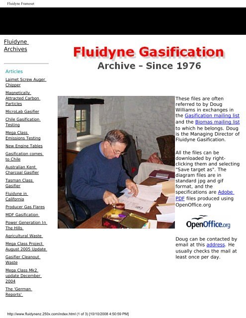
<strong>Fluidyne</strong> <strong>Frameset</strong><strong>Fluidyne</strong>ArchivesArticlesLaimet Screw AugerChipperMagneticallyAttracted CarbonParticlesMicroLab GasifierChile GasificationTestingMega ClassEmissions TestingNew Engine TablesGasification comesto ChileAustralian KentCharcoal GasifierTasman ClassGasifier<strong>Fluidyne</strong> inCaliforniaProducer Gas FlaresThese files are oftenreferred to by DougWilliams in exchanges inthe Gasification mailing listand the Biomas mailing listto which he belongs. Dougis the Managing Director of<strong>Fluidyne</strong> Gasification.All the files can bedownloaded by rightclickingthem and selecting"Save target as". Thediagram files are instandard jpg and gifformat, and thespecifications are AdobePDF files produced usingOpenOffice.orgMDF GasificationPower Generation InThe HillsAgricultural WasteMega Class ProjectAugust 2005 UpdateGasifier CleanoutWasteDoug can be contacted byemail at this address. Heusually checks the mail atleast once per day.Mega Class Mk2update December2004The 'GermanReports'http://www.fluidynenz.250x.com/index.html (1 of 3) [10/10/2008 4:50:59 PM]
<strong>Fluidyne</strong> <strong>Frameset</strong>Mega Class Mk2update June July2004Australian WW2GasifierMega Class Mk 2Pacific Class No 15Micro Class GasifierFischer-TrospheKey Links:InnovationTechnologiesIrelandLimitedGasificationAustraliaDeath of a habitatWood Chip bunkerDrierCheap workingGasifierSimple ChipGuillotineScrew AugerChippersAnniversary GasifierprojectProject Design file(PDF 516kb)New Mega ClassProjectDiagramsHow gas is madePacific Class flowPacific Class lineOpen CoreFerrocementdiagramSpecificationsPacific Class (PDFformat)ArchivesEngine TablesProducer Gas EngineOil and Soothttp://www.fluidynenz.250x.com/index.html (2 of 3) [10/10/2008 4:50:59 PM]
<strong>Fluidyne</strong> <strong>Frameset</strong>Carbon BlackWorld War IIGasifiersForestrySweetwatersEnginesPacific ClassWood to CharAnother day inparadiseCoppice WillowOther StuffLetter from VesaContact Doughttp://www.fluidynenz.250x.com/index.html (3 of 3) [10/10/2008 4:50:59 PM]
<strong>Fluidyne</strong> index rightThese files are often referred to byDoug Williams in exchanges in theGasification mailing list and theBiomas mailing list to which hebelongs. Doug is the ManagingDirector of <strong>Fluidyne</strong> Gasification.All the files can be downloaded byright-clicking them and selecting"Save target as". The diagram filesare in standard jpg and gif format,and the specifications are Adobe PDFfiles produced using OpenOffice.orgDoug can be contacted by email atthis address. He usually checks themail at least once per day.Key Links:InnovationTechnologiesIrelandLimitedGasificationAustraliahttp://www.fluidynenz.250x.com/_framed/250x/fluidynenz/flir.html (1 of 2) [10/10/2008 4:51:12 PM]
<strong>Fluidyne</strong> index righthttp://www.fluidynenz.250x.com/_framed/250x/fluidynenz/flir.html (2 of 2) [10/10/2008 4:51:12 PM]
<strong>Fluidyne</strong> index rightThese files are often referred to byDoug Williams in exchanges in theGasification mailing list and theBiomas mailing list to which hebelongs. Doug is the ManagingDirector of <strong>Fluidyne</strong> Gasification.All the files can be downloaded byright-clicking them and selecting"Save target as". The diagram filesare in standard jpg and gif format,and the specifications are Adobe PDFfiles produced using OpenOffice.orgDoug can be contacted by email atthis address. He usually checks themail at least once per day.Key Links:InnovationTechnologiesIrelandLimitedGasificationAustraliahttp://www.fluidynenz.250x.com/flir.html (1 of 2) [10/10/2008 4:51:13 PM]
<strong>Fluidyne</strong> index righthttp://www.fluidynenz.250x.com/flir.html (2 of 2) [10/10/2008 4:51:13 PM]
Laimet Screw Auger ChipperLaimet Screw Auger ChipperFuel preparation for commercial gasification projects, especially those of large size, has been a major problemfor those seeking to change over to renewable biomass available from forestry activity. With only smaller finechips from conventional plate or drum chipping technology, it is difficult to obtain a fuel chip specification tomeet the needs of charcoal size in the packed bed of gasifiers.I first saw the screw auger chipper sold as the Sasmo brand back in 1985, and have always believed thismethod could replace the traditional wood block fuel, and eventually in 2000, tested chips cut with a Sasmo inNorthern Ireland. The chips were clean cut, critical to unrestricted flow movement, but very uneven in size dueto the wood coming from storm damaged trees, mainly decaying. This created a lot of fines and dirt likematerial, causing unusual gasification problems. This was resolved by screening.With fuel preparation the critical fuel supply issue, a recommendation was made to purchase the latest versionof the Sasmo chipper, now redesigned and marketed as Laimet HP-25, www.laimet.com for our Californianproject with CalForests. This development project will be reported separately. Tractor driven for these tests,the chipper is now being set up with it's own engine.Given the rare opportunity to actually test out some of the lesser know facts of gasification fuel chip behaviourin a gasifier of know performance, provided positive experience for those attending, that I am sure will percolatedown into other uses and needs for specification sized chip.Chips are not easy to photograph in a way that truthfully convey size, but you can see the changes asexplained in the text.These tests were conducted in August 2008.http://www.fluidynenz.250x.com/_framed/250x/fluidynenz/Oct08/chipper.html (1 of 13) [10/10/2008 4:51:16 PM]
Laimet Screw Auger ChipperThis is the HP25 Laimet screwauger chipperlocated inCalifornia thatwas purchasedto evaluate thismethod of fuelpreparationspecifically forgasificationapplication.http://www.fluidynenz.250x.com/_framed/250x/fluidynenz/Oct08/chipper.html (2 of 13) [10/10/2008 4:51:16 PM]
Laimet Screw Auger ChipperBecause wewere testing fourdifferent speciesof coniferavailable fromthe collectionregion, Thechips wereblown intorecycled fertilizerbags forseparategasificationtrials.http://www.fluidynenz.250x.com/_framed/250x/fluidynenz/Oct08/chipper.html (3 of 13) [10/10/2008 4:51:16 PM]
Laimet Screw Auger ChipperHaving waitedsince 1985 to getto use one ofthese machines,the first log hadto be signed offby all involved.http://www.fluidynenz.250x.com/_framed/250x/fluidynenz/Oct08/chipper.html (4 of 13) [10/10/2008 4:51:16 PM]
Laimet Screw Auger ChipperWe tested threesizes of screwauger blades,and this is fromthe smallestblade.Having the firstlog stick and stalldue to our overcautious lowRPM speedlevel, providedthis photo of howthe chip cutsdevelop using ascrew motion.http://www.fluidynenz.250x.com/_framed/250x/fluidynenz/Oct08/chipper.html (5 of 13) [10/10/2008 4:51:16 PM]
Laimet Screw Auger ChipperInstead of liftingfull length logs,we cut them into5ft (1.5m)lengths foreasier handlingby hand. Thefinish site willincorporateequipment forfull log handling.Each 5ft lengthtook threeseconds to chip.These are themedium chip,and take note ofhttp://www.fluidynenz.250x.com/_framed/250x/fluidynenz/Oct08/chipper.html (6 of 13) [10/10/2008 4:51:16 PM]
Laimet Screw Auger Chipperthe average size,compared to thefollowingdiffering species.Medium chip, butsmaller sizerange.http://www.fluidynenz.250x.com/_framed/250x/fluidynenz/Oct08/chipper.html (7 of 13) [10/10/2008 4:51:16 PM]
Laimet Screw Auger ChipperMedium chip,again withdiffering sizerange.This is thebusiness end ofthe LaimetChipper,showing thesmall screwauger beingchanged. Thistook 1.5 hrs withquite a strugglehttp://www.fluidynenz.250x.com/_framed/250x/fluidynenz/Oct08/chipper.html (8 of 13) [10/10/2008 4:51:16 PM]
Laimet Screw Auger Chipperuntil we learntthe tricks notcovered in theinstructionmanual. Wechanged theblades four timesin ten days, butthis is notnormally doneonce in use.The screwaugers areshipped like this,in a cage that isused to returnthe augers backto the factory fortotal rebuilding.The blade edgesare like razors,and very hard.The big screw ison the right, andmedium on theleft.http://www.fluidynenz.250x.com/_framed/250x/fluidynenz/Oct08/chipper.html (9 of 13) [10/10/2008 4:51:16 PM]
Laimet Screw Auger ChipperThis is thebiggest chipsize, and as youcan see, it has agood chunkystructure.The same bigchip/chunk sideon, showinghttp://www.fluidynenz.250x.com/_framed/250x/fluidynenz/Oct08/chipper.html (10 of 13) [10/10/2008 4:51:16 PM]
Laimet Screw Auger Chippernone of thelinear fracturingcommonly seenin small chips.Changingspecies, the bigchip/chunkchanges it's sizeratios, andshatteringproduces morefines. Woodmoisture alsoplay a big part inhow the chipcuts.http://www.fluidynenz.250x.com/_framed/250x/fluidynenz/Oct08/chipper.html (11 of 13) [10/10/2008 4:51:16 PM]
Laimet Screw Auger ChipperFrom previousexperience offines in chip, wescreened out thefine bark andwhatever elsefell through thescreen. Thesefines alwaysgravitate to thebottom of piles,and get pickedup as a slug,causing acomplete changeto the stagedchar evolution ina packed carbonbed common tomany gasifiers.Note theoversized endchunks from thelog. These tooneed separatinghttp://www.fluidynenz.250x.com/_framed/250x/fluidynenz/Oct08/chipper.html (12 of 13) [10/10/2008 4:51:16 PM]
Laimet Screw Auger Chipperout as their charevolves at adiffering rate tothe averagesmall chiphttp://www.fluidynenz.250x.com/_framed/250x/fluidynenz/Oct08/chipper.html (13 of 13) [10/10/2008 4:51:16 PM]
Laimet Screw Auger ChipperLaimet Screw Auger ChipperFuel preparation for commercial gasification projects, especially those of large size, has been a major problemfor those seeking to change over to renewable biomass available from forestry activity. With only smaller finechips from conventional plate or drum chipping technology, it is difficult to obtain a fuel chip specification tomeet the needs of charcoal size in the packed bed of gasifiers.I first saw the screw auger chipper sold as the Sasmo brand back in 1985, and have always believed thismethod could replace the traditional wood block fuel, and eventually in 2000, tested chips cut with a Sasmo inNorthern Ireland. The chips were clean cut, critical to unrestricted flow movement, but very uneven in size dueto the wood coming from storm damaged trees, mainly decaying. This created a lot of fines and dirt likematerial, causing unusual gasification problems. This was resolved by screening.With fuel preparation the critical fuel supply issue, a recommendation was made to purchase the latest versionof the Sasmo chipper, now redesigned and marketed as Laimet HP-25, www.laimet.com for our Californianproject with CalForests. This development project will be reported separately. Tractor driven for these tests,the chipper is now being set up with it's own engine.Given the rare opportunity to actually test out some of the lesser know facts of gasification fuel chip behaviourin a gasifier of know performance, provided positive experience for those attending, that I am sure will percolatedown into other uses and needs for specification sized chip.Chips are not easy to photograph in a way that truthfully convey size, but you can see the changes asexplained in the text.These tests were conducted in August 2008.http://www.fluidynenz.250x.com/Oct08/chipper.html (1 of 13) [10/10/2008 4:51:19 PM]
Laimet Screw Auger ChipperThis is the HP25 Laimet screwauger chipperlocated inCalifornia thatwas purchasedto evaluate thismethod of fuelpreparationspecifically forgasificationapplication.http://www.fluidynenz.250x.com/Oct08/chipper.html (2 of 13) [10/10/2008 4:51:19 PM]
Laimet Screw Auger ChipperBecause wewere testing fourdifferent speciesof coniferavailable fromthe collectionregion, Thechips wereblown intorecycled fertilizerbags forseparategasificationtrials.http://www.fluidynenz.250x.com/Oct08/chipper.html (3 of 13) [10/10/2008 4:51:19 PM]
Laimet Screw Auger ChipperHaving waitedsince 1985 to getto use one ofthese machines,the first log hadto be signed offby all involved.http://www.fluidynenz.250x.com/Oct08/chipper.html (4 of 13) [10/10/2008 4:51:19 PM]
Laimet Screw Auger ChipperWe tested threesizes of screwauger blades,and this is fromthe smallestblade.Having the firstlog stick and stalldue to our overcautious lowRPM speedlevel, providedthis photo of howthe chip cutsdevelop using ascrew motion.http://www.fluidynenz.250x.com/Oct08/chipper.html (5 of 13) [10/10/2008 4:51:19 PM]
Laimet Screw Auger ChipperInstead of liftingfull length logs,we cut them into5ft (1.5m)lengths foreasier handlingby hand. Thefinish site willincorporateequipment forfull log handling.Each 5ft lengthtook threeseconds to chip.These are themedium chip,and take note ofhttp://www.fluidynenz.250x.com/Oct08/chipper.html (6 of 13) [10/10/2008 4:51:19 PM]
Laimet Screw Auger Chipperthe average size,compared to thefollowingdiffering species.Medium chip, butsmaller sizerange.http://www.fluidynenz.250x.com/Oct08/chipper.html (7 of 13) [10/10/2008 4:51:19 PM]
Laimet Screw Auger ChipperMedium chip,again withdiffering sizerange.This is thebusiness end ofthe LaimetChipper,showing thesmall screwauger beingchanged. Thistook 1.5 hrs withquite a strugglehttp://www.fluidynenz.250x.com/Oct08/chipper.html (8 of 13) [10/10/2008 4:51:19 PM]
Laimet Screw Auger Chipperuntil we learntthe tricks notcovered in theinstructionmanual. Wechanged theblades four timesin ten days, butthis is notnormally doneonce in use.The screwaugers areshipped like this,in a cage that isused to returnthe augers backto the factory fortotal rebuilding.The blade edgesare like razors,and very hard.The big screw ison the right, andmedium on theleft.http://www.fluidynenz.250x.com/Oct08/chipper.html (9 of 13) [10/10/2008 4:51:19 PM]
Laimet Screw Auger ChipperThis is thebiggest chipsize, and as youcan see, it has agood chunkystructure.The same bigchip/chunk sideon, showinghttp://www.fluidynenz.250x.com/Oct08/chipper.html (10 of 13) [10/10/2008 4:51:19 PM]
Laimet Screw Auger Chippernone of thelinear fracturingcommonly seenin small chips.Changingspecies, the bigchip/chunkchanges it's sizeratios, andshatteringproduces morefines. Woodmoisture alsoplay a big part inhow the chipcuts.http://www.fluidynenz.250x.com/Oct08/chipper.html (11 of 13) [10/10/2008 4:51:19 PM]
Laimet Screw Auger ChipperFrom previousexperience offines in chip, wescreened out thefine bark andwhatever elsefell through thescreen. Thesefines alwaysgravitate to thebottom of piles,and get pickedup as a slug,causing acomplete changeto the stagedchar evolution ina packed carbonbed common tomany gasifiers.Note theoversized endchunks from thelog. These tooneed separatinghttp://www.fluidynenz.250x.com/Oct08/chipper.html (12 of 13) [10/10/2008 4:51:19 PM]
Laimet Screw Auger Chipperout as their charevolves at adiffering rate tothe averagesmall chiphttp://www.fluidynenz.250x.com/Oct08/chipper.html (13 of 13) [10/10/2008 4:51:19 PM]
Magnetically Attracted Carbon ParticlesMagnetically Attracted Carbon ParticlesDiscovered while conducting packed charcoal bed analysis of an Andes Class gasifier, some of the fine carbondust located in the oxidation zone of the gas making process, were found to be attracted to a magnet. Whileunusual to see carbon sticking to a magnet, a number of explanations have been offered, with the most likelyone, that trace elements such as iron migrate with the pyrolysis gases, and carbonize in the oxidation zone.This is only a simple explanation, the truth is probably a little more complex. The photos tell their own story, andI can only apologise for my poor photography.September 2008.With the background dusthttp://www.fluidynenz.250x.com/_framed/250x/fluidynenz/Sept08/mcarbon.html (1 of 8) [10/10/2008 4:51:21 PM]
Magnetically Attracted Carbon Particlesseparated, theremainingparticles join toform a miniaturevertical carbonforest.http://www.fluidynenz.250x.com/_framed/250x/fluidynenz/Sept08/mcarbon.html (2 of 8) [10/10/2008 4:51:21 PM]
Magnetically Attracted Carbon ParticlesThis shows thetiny blister likereflective nodules,which suggeststhis carbon iscarbonized tarfrom the pyrolisisgases.http://www.fluidynenz.250x.com/_framed/250x/fluidynenz/Sept08/mcarbon.html (3 of 8) [10/10/2008 4:51:21 PM]
Magnetically Attracted Carbon ParticlesWith the nakedeye, these carbontrees looked likePine, or Fir trees.http://www.fluidynenz.250x.com/_framed/250x/fluidynenz/Sept08/mcarbon.html (4 of 8) [10/10/2008 4:51:21 PM]
Magnetically Attracted Carbon ParticlesVery difficult toget the 3D effect.http://www.fluidynenz.250x.com/_framed/250x/fluidynenz/Sept08/mcarbon.html (5 of 8) [10/10/2008 4:51:21 PM]
Magnetically Attracted Carbon ParticlesA side viewthrough thecontainer, showsthe carbon treesstanding.A couple of roguetrees grow awayfrom the mainbunch!http://www.fluidynenz.250x.com/_framed/250x/fluidynenz/Sept08/mcarbon.html (6 of 8) [10/10/2008 4:51:21 PM]
Magnetically Attracted Carbon ParticlesFuzzy, but just toshow anotherview.The magnet sethttp://www.fluidynenz.250x.com/_framed/250x/fluidynenz/Sept08/mcarbon.html (7 of 8) [10/10/2008 4:51:21 PM]
Magnetically Attracted Carbon Particlesbelow thecontained sampleextracted from themass in the background. Only atiny proportion ofthe char sampledhad this magneticattraction.http://www.fluidynenz.250x.com/_framed/250x/fluidynenz/Sept08/mcarbon.html (8 of 8) [10/10/2008 4:51:21 PM]
Magnetically Attracted Carbon ParticlesMagnetically Attracted Carbon ParticlesDiscovered while conducting packed charcoal bed analysis of an Andes Class gasifier, some of the fine carbondust located in the oxidation zone of the gas making process, were found to be attracted to a magnet. Whileunusual to see carbon sticking to a magnet, a number of explanations have been offered, with the most likelyone, that trace elements such as iron migrate with the pyrolysis gases, and carbonize in the oxidation zone.This is only a simple explanation, the truth is probably a little more complex. The photos tell their own story, andI can only apologise for my poor photography.September 2008.With the background dusthttp://www.fluidynenz.250x.com/Sept08/mcarbon.html (1 of 8) [10/10/2008 4:51:23 PM]
Magnetically Attracted Carbon Particlesseparated, theremainingparticles join toform a miniaturevertical carbonforest.http://www.fluidynenz.250x.com/Sept08/mcarbon.html (2 of 8) [10/10/2008 4:51:23 PM]
Magnetically Attracted Carbon ParticlesThis shows thetiny blister likereflective nodules,which suggeststhis carbon iscarbonized tarfrom the pyrolisisgases.http://www.fluidynenz.250x.com/Sept08/mcarbon.html (3 of 8) [10/10/2008 4:51:23 PM]
Magnetically Attracted Carbon ParticlesWith the nakedeye, these carbontrees looked likePine, or Fir trees.http://www.fluidynenz.250x.com/Sept08/mcarbon.html (4 of 8) [10/10/2008 4:51:23 PM]
Magnetically Attracted Carbon ParticlesVery difficult toget the 3D effect.http://www.fluidynenz.250x.com/Sept08/mcarbon.html (5 of 8) [10/10/2008 4:51:23 PM]
Magnetically Attracted Carbon ParticlesA side viewthrough thecontainer, showsthe carbon treesstanding.A couple of roguetrees grow awayfrom the mainbunch!http://www.fluidynenz.250x.com/Sept08/mcarbon.html (6 of 8) [10/10/2008 4:51:23 PM]
Magnetically Attracted Carbon ParticlesFuzzy, but just toshow anotherview.The magnet sethttp://www.fluidynenz.250x.com/Sept08/mcarbon.html (7 of 8) [10/10/2008 4:51:23 PM]
Magnetically Attracted Carbon Particlesbelow thecontained sampleextracted from themass in the background. Only atiny proportion ofthe char sampledhad this magneticattraction.http://www.fluidynenz.250x.com/Sept08/mcarbon.html (8 of 8) [10/10/2008 4:51:23 PM]
MicroLabMicroLabIn recent years, the interest in gasification has seen many researchers trying to set up projectsfor fuel testing, with equipment that is out of sync with the realities of applied gasificationprinciples. Bench top testing of very small amounts of fuel, certainly provides useful information,but this often cannot be extended to apply to the realities of gasification on a usable commercialscale.Small gasifiers are very rare to find from commercial manufactures, especially for raw biomass,as these sizes were proven to be more suited to charcoal fuels, and this project showing theMicrolab gasifier, was prepared as a special favour to add a gasification facility to the Universityof Ulster, Northern Ireland. It is set up to enable the gas to be blown out hot with only cycloniccleaning, or pass through a separated second cyclone and gas cooling cleaning system that canbe used to run an engine of about 1 litre cylinder capacity (at 1500 rpm). As a micro gasificationprocess, the small dimensions behave exactly as the larger systems, but still must conform tofuel specification in relation to the set parameters. As an opportunity to study gasification at thislevel, it provided me with a rare chance to compare charcoal and wood at a manageable level,and my own research stumbled a few steps forward during the proving trials.Gasification gives up it's secrets very reluctantly, and it is my hope that this gasifier will assist toprovide a new generation of informed people who choose to pursue this technology from aninformed base line. Size might create the impression that it is perfect for domestic application,but that will be for others to decide, as a market cannot be developed building these one at atime. Having built this system to meet the evolving expectations of a modern World withregulations etc, it will provide a safe and reliable tool for many years to the students of UlsterUniversity.Specifications:Gasifier Type.Maximum Output.Maximum Fuel ConsumptionFuel Hopper Test VolumeDowndraft (throated tar cracking)9.8Nm3/hr4.5 kg/hr3 litreshttp://www.fluidynenz.250x.com/_framed/250x/fluidynenz/jul08/microlab.html (1 of 14) [10/10/2008 4:51:25 PM]
MicroLabTest Time Duration20 minutesFront viewshowing thecabinetenclosure of allhotcomponents,with basicinstrumentationof threemanometersand digitalthermometer.http://www.fluidynenz.250x.com/_framed/250x/fluidynenz/jul08/microlab.html (2 of 14) [10/10/2008 4:51:25 PM]
MicroLabInteriorcomponents R-L Gasifier,Blast tube,Twin Cycloneswith single sootpot (changedto separatepots later)http://www.fluidynenz.250x.com/_framed/250x/fluidynenz/jul08/microlab.html (3 of 14) [10/10/2008 4:51:25 PM]
MicroLabRear viewshowingsawdust filterand main gascooling fan.http://www.fluidynenz.250x.com/_framed/250x/fluidynenz/jul08/microlab.html (4 of 14) [10/10/2008 4:51:25 PM]
MicroLabHot air exit,and air supplyhoses to testflare nozzle,which acts asaspirator forsuction ignitionof hearthmodulehttp://www.fluidynenz.250x.com/_framed/250x/fluidynenz/jul08/microlab.html (5 of 14) [10/10/2008 4:51:25 PM]
MicroLabTest flarenozzle,showing hotgas suctionaspirator undernozzleactuated withlow pressureair, andtangentialcombustion airinto nozzle.http://www.fluidynenz.250x.com/_framed/250x/fluidynenz/jul08/microlab.html (6 of 14) [10/10/2008 4:51:25 PM]
MicroLabReady fortesting insidebuilding, showsthat theinstrumentpanel swingsaround to suitposition ofoperator.Manometerhoses areconcealed inpipe support.First timeignition showsthe classicalhttp://www.fluidynenz.250x.com/_framed/250x/fluidynenz/jul08/microlab.html (7 of 14) [10/10/2008 4:51:25 PM]
MicroLabincandescentoxidation zone.While thisindicatescorrecttemperatures,it is only onefactor ofmaking a tarfree gasFirst gas, butcamera flashkilled themoment, butyou can justsee it againstthe background of thedoor.http://www.fluidynenz.250x.com/_framed/250x/fluidynenz/jul08/microlab.html (8 of 14) [10/10/2008 4:51:25 PM]
MicroLabAs our day waslong, this shotat night showsthe test flareburning with allthe fineparticulate,which due to aglitch, the hotcycloneejected.http://www.fluidynenz.250x.com/_framed/250x/fluidynenz/jul08/microlab.html (9 of 14) [10/10/2008 4:51:25 PM]
MicroLabThe dustejection wasfixed byseparating thecyclones froma single sootbox, intoseparatedboxeshttp://www.fluidynenz.250x.com/_framed/250x/fluidynenz/jul08/microlab.html (10 of 14) [10/10/2008 4:51:25 PM]
MicroLabNow free ofdust, the testflare has lostthe red ting ofburning soot.Thetemperaturewas prettysteady (+ or -10C) over alltests at justunder 700C.As the firsttests were alsohttp://www.fluidynenz.250x.com/_framed/250x/fluidynenz/jul08/microlab.html (11 of 14) [10/10/2008 4:51:25 PM]
MicroLabto test the gascooling, thedust ejectionalso went intothecondensateresulting in thisvery blacksample.The first blackcondensatesample is onthe left after acouple of daysto settle. Thesample on theright is afterthe soot boxeswere fitted,and has onlybeen standingone day. Bothsamples areparticles inhttp://www.fluidynenz.250x.com/_framed/250x/fluidynenz/jul08/microlab.html (12 of 14) [10/10/2008 4:51:25 PM]
MicroLabsuspensionwhich willsettle out, nottoxic blackliquor whichhashydrocarbonsin solution. Thebrown colourcomes fromdissolved ash,giving theaqueouscondensate apH of 8.2The fuel forthis size ofgasifier can bethick smallchips, or thesesugar lumpsize sawn andchoppedblocks. It isimportant thatthe charcoalformed is froma size that cancarbonise,oxidize, andreduce as itshrinks involume,without closingthe interstitialspace of thehttp://www.fluidynenz.250x.com/_framed/250x/fluidynenz/jul08/microlab.html (13 of 14) [10/10/2008 4:51:26 PM]
MicroLabpacked bed.This final photoshows the charas it changesboth volumeand size as itpassesthrough eachstage of thisgasificationprocess.http://www.fluidynenz.250x.com/_framed/250x/fluidynenz/jul08/microlab.html (14 of 14) [10/10/2008 4:51:26 PM]
MicroLabMicroLabIn recent years, the interest in gasification has seen many researchers trying to set up projectsfor fuel testing, with equipment that is out of sync with the realities of applied gasificationprinciples. Bench top testing of very small amounts of fuel, certainly provides useful information,but this often cannot be extended to apply to the realities of gasification on a usable commercialscale.Small gasifiers are very rare to find from commercial manufactures, especially for raw biomass,as these sizes were proven to be more suited to charcoal fuels, and this project showing theMicrolab gasifier, was prepared as a special favour to add a gasification facility to the Universityof Ulster, Northern Ireland. It is set up to enable the gas to be blown out hot with only cycloniccleaning, or pass through a separated second cyclone and gas cooling cleaning system that canbe used to run an engine of about 1 litre cylinder capacity (at 1500 rpm). As a micro gasificationprocess, the small dimensions behave exactly as the larger systems, but still must conform tofuel specification in relation to the set parameters. As an opportunity to study gasification at thislevel, it provided me with a rare chance to compare charcoal and wood at a manageable level,and my own research stumbled a few steps forward during the proving trials.Gasification gives up it's secrets very reluctantly, and it is my hope that this gasifier will assist toprovide a new generation of informed people who choose to pursue this technology from aninformed base line. Size might create the impression that it is perfect for domestic application,but that will be for others to decide, as a market cannot be developed building these one at atime. Having built this system to meet the evolving expectations of a modern World withregulations etc, it will provide a safe and reliable tool for many years to the students of UlsterUniversity.Specifications:Gasifier Type.Maximum Output.Maximum Fuel ConsumptionFuel Hopper Test VolumeDowndraft (throated tar cracking)9.8Nm3/hr4.5 kg/hr3 litreshttp://www.fluidynenz.250x.com/jul08/microlab.html (1 of 14) [10/10/2008 4:51:28 PM]
MicroLabTest Time Duration20 minutesFront viewshowing thecabinetenclosure of allhotcomponents,with basicinstrumentationof threemanometersand digitalthermometer.http://www.fluidynenz.250x.com/jul08/microlab.html (2 of 14) [10/10/2008 4:51:28 PM]
MicroLabInteriorcomponents R-L Gasifier,Blast tube,Twin Cycloneswith single sootpot (changedto separatepots later)http://www.fluidynenz.250x.com/jul08/microlab.html (3 of 14) [10/10/2008 4:51:28 PM]
MicroLabRear viewshowingsawdust filterand main gascooling fan.http://www.fluidynenz.250x.com/jul08/microlab.html (4 of 14) [10/10/2008 4:51:28 PM]
MicroLabHot air exit,and air supplyhoses to testflare nozzle,which acts asaspirator forsuction ignitionof hearthmodulehttp://www.fluidynenz.250x.com/jul08/microlab.html (5 of 14) [10/10/2008 4:51:28 PM]
MicroLabTest flarenozzle,showing hotgas suctionaspirator undernozzleactuated withlow pressureair, andtangentialcombustion airinto nozzle.http://www.fluidynenz.250x.com/jul08/microlab.html (6 of 14) [10/10/2008 4:51:28 PM]
MicroLabReady fortesting insidebuilding, showsthat theinstrumentpanel swingsaround to suitposition ofoperator.Manometerhoses areconcealed inpipe support.First timeignition showsthe classicalhttp://www.fluidynenz.250x.com/jul08/microlab.html (7 of 14) [10/10/2008 4:51:28 PM]
MicroLabincandescentoxidation zone.While thisindicatescorrecttemperatures,it is only onefactor ofmaking a tarfree gasFirst gas, butcamera flashkilled themoment, butyou can justsee it againstthe background of thedoor.http://www.fluidynenz.250x.com/jul08/microlab.html (8 of 14) [10/10/2008 4:51:28 PM]
MicroLabAs our day waslong, this shotat night showsthe test flareburning with allthe fineparticulate,which due to aglitch, the hotcycloneejected.http://www.fluidynenz.250x.com/jul08/microlab.html (9 of 14) [10/10/2008 4:51:28 PM]
MicroLabThe dustejection wasfixed byseparating thecyclones froma single sootbox, intoseparatedboxeshttp://www.fluidynenz.250x.com/jul08/microlab.html (10 of 14) [10/10/2008 4:51:28 PM]
MicroLabNow free ofdust, the testflare has lostthe red ting ofburning soot.Thetemperaturewas prettysteady (+ or -10C) over alltests at justunder 700C.As the firsttests were alsohttp://www.fluidynenz.250x.com/jul08/microlab.html (11 of 14) [10/10/2008 4:51:28 PM]
MicroLabto test the gascooling, thedust ejectionalso went intothecondensateresulting in thisvery blacksample.The first blackcondensatesample is onthe left after acouple of daysto settle. Thesample on theright is afterthe soot boxeswere fitted,and has onlybeen standingone day. Bothsamples areparticles inhttp://www.fluidynenz.250x.com/jul08/microlab.html (12 of 14) [10/10/2008 4:51:28 PM]
MicroLabsuspensionwhich willsettle out, nottoxic blackliquor whichhashydrocarbonsin solution. Thebrown colourcomes fromdissolved ash,giving theaqueouscondensate apH of 8.2The fuel forthis size ofgasifier can bethick smallchips, or thesesugar lumpsize sawn andchoppedblocks. It isimportant thatthe charcoalformed is froma size that cancarbonise,oxidize, andreduce as itshrinks involume,without closingthe interstitialspace of thehttp://www.fluidynenz.250x.com/jul08/microlab.html (13 of 14) [10/10/2008 4:51:28 PM]
MicroLabpacked bed.This final photoshows the charas it changesboth volumeand size as itpassesthrough eachstage of thisgasificationprocess.http://www.fluidynenz.250x.com/jul08/microlab.html (14 of 14) [10/10/2008 4:51:28 PM]
Chile Gasification TestingChile Gasification TestingWhen it becomes necessary for producer gas to replace LPG or natural gas in the commercial sectorof any country, locally manufactured gasifiers of appropriate design is a major first step. Surprisingly,there are considerable variations in designs of ancillary systems needed from place to place, wherethe gases are used for a multitude of process heat applications. There is also the need tomanufacture with materials that each country can supply and service.When Douglas Diaz of Creapor SA. in Santiago Chile requested my assistance to assess gasificationin April 2007 ( See, Gasification comes to Chile), I agreed to provide <strong>Fluidyne</strong> Technology to explorethe potential market applications using larger gasifiers. The following photos show some of the activityduring my visit April 2008 to test the larger gasifier, which has been given the identification ofthe "Andes Class", in keeping with the regions for which it has been designed. The gasifier wasconstructed within a three week period, prior to my arrival.In the test situation, none of the automation was fitted, although the internal mechanisms were inplace, and could be, and were operated manually. This allowed an evaluation to be made to adaptlocally available technology to these systems, and to provide operating experience as to why systemscan be both beneficial or detrimental to a gasifiers operational reliability. It also enables amanufacturer to be tested on the level of understanding to each modal of technology transfer.When conducting operator training programmes with the gasifier, first the manufacturer, then keycompany staff, are given a written and practical test, again in modular format, providing a capability tothen work without direct supervision regarding the gasification process. Previous experience hasproven that gasifiers supplied without training support, is a waste of time and investment to allconcerned.In providing this project profile, I have taken the opportunity to show how fast wood can turn intocharcoal reducing in size, only as it begins to enter the oxidation zone, which in this blown gasifier, isslightly above the air nozzles. No raw wood should be seen in the oxidation zone, as the amount ofendothermic heat needed to drive the gas making process, can only be achieved from a packedcharcoal bed. Many incorrect descriptions exist of this process from wood to charcoal in a downdraftgasifier of this type, so take a minute to appreciate how critical this is to making a tar free gas. At fulloutput of about 300kWt, the flow rate of fuel through this zone is 2kg/minute.Also tested for the first time (by ourselves), was a ceramic combustion chamber concept of the"Cyclomix Burner", we developed for producer gas application. It was sized at only 25% of the gasoutput, so use your imagination to see four of these blocks all burning at the same time. The ceramichttp://www.fluidynenz.250x.com/_framed/250x/fluidynenz/chilie/chilie.html (1 of 21) [10/10/2008 4:51:32 PM]
Chile Gasification Testingcomponent concept is not new, but is an area of expertise that this company can add, providing awider application for producer gas heating. This was only a test of concept, which considering the gashad no dust cleaning systems, burnt very cleanly without odour or smoke during the testing. Smokedoes appear when producer gas is combusted, where high levels of CO2 are in the gas beforecombustion.Of special mention, the fuel wood preparation. It was an excellent use of my time to cut the woodblocks for these tests, having manually cut many tonnes during the last 32 years. It is not a waste oftime where rural jobs are few, and incomes are desperately needed, where cut dry wood becomes avaluable local resource for gasified installations. Fuel wood chips specifically appropriate for gasifiersdo not exist in the wider context of wood chipping, and is an ongoing priority in the work that I amassociated.The company Creapor SA. also manufacture hot water boiler heating systems, for which they havean active development programme, as well as an assembly line for popular sizes. They have allowedme to show you a couple of photos during factory testing, which was interesting for me to see a realgasifying type combustion process in application.Doug Williams.May 2008.IMG_0189.jpg 1.When there is nohttp://www.fluidynenz.250x.com/_framed/250x/fluidynenz/chilie/chilie.html (2 of 21) [10/10/2008 4:51:32 PM]
Chile Gasification Testingprior experience ofpreparing gasifierfuel, there is onlyone way to begin,using basic manuallabour, mine in thiscase.http://www.fluidynenz.250x.com/_framed/250x/fluidynenz/chilie/chilie.html (3 of 21) [10/10/2008 4:51:32 PM]
Chile Gasification TestingIMG_0188.jpg 2.After the logs areaxe split into billets,a tungsten bladetip saw cut theblocks to a mixtureof sizes.IMG_0076.jpg 3.The finished fuel hadhttp://www.fluidynenz.250x.com/_framed/250x/fluidynenz/chilie/chilie.html (4 of 21) [10/10/2008 4:51:32 PM]
Chile Gasification Testinga bulk density ofabout 350kg/m3,average for blockEucalyptus fuel dry,ready forgasification.IMG_0043.jpg 4.http://www.fluidynenz.250x.com/_framed/250x/fluidynenz/chilie/chilie.html (5 of 21) [10/10/2008 4:51:32 PM]
Chile Gasification TestingChecking the gasifiercomponents beforefinal assembly. Thisworkshop works toISO 2000.http://www.fluidynenz.250x.com/_framed/250x/fluidynenz/chilie/chilie.html (6 of 21) [10/10/2008 4:51:32 PM]
Chile Gasification TestingIMG_0064.jpg 5.Final assemblychecks beforepainting and testing.http://www.fluidynenz.250x.com/_framed/250x/fluidynenz/chilie/chilie.html (7 of 21) [10/10/2008 4:51:32 PM]
Chile Gasification TestingIMG_0253.jpg 6.Ready for testingwith temporaryremovable start-uphose.IMG_0256.jpg 7.http://www.fluidynenz.250x.com/_framed/250x/fluidynenz/chilie/chilie.html (8 of 21) [10/10/2008 4:51:32 PM]
Chile Gasification TestingNew design ofceramic combustionchambers were alsobeing tested for thisdevelopmentprogramme. Thehanging ball is theweight to hold thefuel lockclosed duringmanually operatedtest programme.http://www.fluidynenz.250x.com/_framed/250x/fluidynenz/chilie/chilie.html (9 of 21) [10/10/2008 4:51:32 PM]
Chile Gasification TestingIMG_0211.jpg 8.First start-up was incold foggy conditions(10C), Ignition was 7seconds, and firstgas within 1.5minutes.IMG_0219.jpg 9.http://www.fluidynenz.250x.com/_framed/250x/fluidynenz/chilie/chilie.html (10 of 21) [10/10/2008 4:51:32 PM]
Chile Gasification TestingFirst test is to checkcolour of oxidationzone, which showsdesired colour likethe sun.IMG_0216.jpg 10.http://www.fluidynenz.250x.com/_framed/250x/fluidynenz/chilie/chilie.html (11 of 21) [10/10/2008 4:51:32 PM]
Chile Gasification TestingFirst gas billowingout, and undergoing"sniff" test forodours. This is nota joke comment.http://www.fluidynenz.250x.com/_framed/250x/fluidynenz/chilie/chilie.html (12 of 21) [10/10/2008 4:51:32 PM]
Chile Gasification TestingIMG_0205.jpg 11.Looking directlydown the centralcombustion nozzleafter combustion airadded.http://www.fluidynenz.250x.com/_framed/250x/fluidynenz/chilie/chilie.html (13 of 21) [10/10/2008 4:51:32 PM]
Chile Gasification TestingIMG_0208.jpg 12.Douglas Diaz on theleft, Doug Williamson the right,obviously happy withfirst test.IMG_0227.jpg 13.This is the fuelhttp://www.fluidynenz.250x.com/_framed/250x/fluidynenz/chilie/chilie.html (14 of 21) [10/10/2008 4:51:32 PM]
Chile Gasification Testing150mm above airnozzles. Note charouter ring, and rawwood centrally. Atfull output, the fuelconsumption is2kg/minute.IMG_0228.jpg 14.At 75mm above theair nozzles, the outerchar ringincreases,while thecentral raw, ortorrified wood areashrinking.http://www.fluidynenz.250x.com/_framed/250x/fluidynenz/chilie/chilie.html (15 of 21) [10/10/2008 4:51:32 PM]
Chile Gasification TestingIMG_0229.jpg 15.At 50mm above theair nozzles, the rawwood has almostcompletely turned tochar.IMG_0231.jpg 16.At 24mm above theair nozzles thehttp://www.fluidynenz.250x.com/_framed/250x/fluidynenz/chilie/chilie.html (16 of 21) [10/10/2008 4:51:32 PM]
Chile Gasification Testingcentral bed wasalmost completecharcoal, and at theair nozzle level, all20mm beads ofcharcoal. This photowas missed due toflat camera batteries.http://www.fluidynenz.250x.com/_framed/250x/fluidynenz/chilie/chilie.html (17 of 21) [10/10/2008 4:51:32 PM]
Chile Gasification TestingIMG_0240.jpg 17.This is the first viewof the waste char,which is low gradeactivated carbon. theamount depends onhow the system isset to serve the endfunction of thegasifier.http://www.fluidynenz.250x.com/_framed/250x/fluidynenz/chilie/chilie.html (18 of 21) [10/10/2008 4:51:32 PM]
Chile Gasification TestingIMG_0244.jpg 18.With fines sievedout, it can be usedas start-up char afterany servicing thatrequires bed cleanout.Correctly sizedchar is important forfirst start-ups.IMG_0091.jpg 20.http://www.fluidynenz.250x.com/_framed/250x/fluidynenz/chilie/chilie.html (19 of 21) [10/10/2008 4:51:32 PM]
Chile Gasification TestingThe companyalso designs andbuilds a variety ofhot water heatingboilers.IMG_0068.jpg 21.Two sizes ofdomestic heatingboilers being testedduring my visit.http://www.fluidynenz.250x.com/_framed/250x/fluidynenz/chilie/chilie.html (20 of 21) [10/10/2008 4:51:32 PM]
Chile Gasification Testinghttp://www.fluidynenz.250x.com/_framed/250x/fluidynenz/chilie/chilie.html (21 of 21) [10/10/2008 4:51:32 PM]
Chile Gasification TestingChile Gasification TestingWhen it becomes necessary for producer gas to replace LPG or natural gas in the commercial sectorof any country, locally manufactured gasifiers of appropriate design is a major first step. Surprisingly,there are considerable variations in designs of ancillary systems needed from place to place, wherethe gases are used for a multitude of process heat applications. There is also the need tomanufacture with materials that each country can supply and service.When Douglas Diaz of Creapor SA. in Santiago Chile requested my assistance to assess gasificationin April 2007 ( See, Gasification comes to Chile), I agreed to provide <strong>Fluidyne</strong> Technology to explorethe potential market applications using larger gasifiers. The following photos show some of the activityduring my visit April 2008 to test the larger gasifier, which has been given the identification ofthe "Andes Class", in keeping with the regions for which it has been designed. The gasifier wasconstructed within a three week period, prior to my arrival.In the test situation, none of the automation was fitted, although the internal mechanisms were inplace, and could be, and were operated manually. This allowed an evaluation to be made to adaptlocally available technology to these systems, and to provide operating experience as to why systemscan be both beneficial or detrimental to a gasifiers operational reliability. It also enables amanufacturer to be tested on the level of understanding to each modal of technology transfer.When conducting operator training programmes with the gasifier, first the manufacturer, then keycompany staff, are given a written and practical test, again in modular format, providing a capability tothen work without direct supervision regarding the gasification process. Previous experience hasproven that gasifiers supplied without training support, is a waste of time and investment to allconcerned.In providing this project profile, I have taken the opportunity to show how fast wood can turn intocharcoal reducing in size, only as it begins to enter the oxidation zone, which in this blown gasifier, isslightly above the air nozzles. No raw wood should be seen in the oxidation zone, as the amount ofendothermic heat needed to drive the gas making process, can only be achieved from a packedcharcoal bed. Many incorrect descriptions exist of this process from wood to charcoal in a downdraftgasifier of this type, so take a minute to appreciate how critical this is to making a tar free gas. At fulloutput of about 300kWt, the flow rate of fuel through this zone is 2kg/minute.Also tested for the first time (by ourselves), was a ceramic combustion chamber concept of the"Cyclomix Burner", we developed for producer gas application. It was sized at only 25% of the gasoutput, so use your imagination to see four of these blocks all burning at the same time. The ceramichttp://www.fluidynenz.250x.com/chilie/chilie.html (1 of 21) [10/10/2008 4:51:35 PM]
Chile Gasification Testingcomponent concept is not new, but is an area of expertise that this company can add, providing awider application for producer gas heating. This was only a test of concept, which considering the gashad no dust cleaning systems, burnt very cleanly without odour or smoke during the testing. Smokedoes appear when producer gas is combusted, where high levels of CO2 are in the gas beforecombustion.Of special mention, the fuel wood preparation. It was an excellent use of my time to cut the woodblocks for these tests, having manually cut many tonnes during the last 32 years. It is not a waste oftime where rural jobs are few, and incomes are desperately needed, where cut dry wood becomes avaluable local resource for gasified installations. Fuel wood chips specifically appropriate for gasifiersdo not exist in the wider context of wood chipping, and is an ongoing priority in the work that I amassociated.The company Creapor SA. also manufacture hot water boiler heating systems, for which they havean active development programme, as well as an assembly line for popular sizes. They have allowedme to show you a couple of photos during factory testing, which was interesting for me to see a realgasifying type combustion process in application.Doug Williams.May 2008.IMG_0189.jpg 1.When there is nohttp://www.fluidynenz.250x.com/chilie/chilie.html (2 of 21) [10/10/2008 4:51:35 PM]
Chile Gasification Testingprior experience ofpreparing gasifierfuel, there is onlyone way to begin,using basic manuallabour, mine in thiscase.http://www.fluidynenz.250x.com/chilie/chilie.html (3 of 21) [10/10/2008 4:51:35 PM]
Chile Gasification TestingIMG_0188.jpg 2.After the logs areaxe split into billets,a tungsten bladetip saw cut theblocks to a mixtureof sizes.IMG_0076.jpg 3.The finished fuel hadhttp://www.fluidynenz.250x.com/chilie/chilie.html (4 of 21) [10/10/2008 4:51:35 PM]
Chile Gasification Testinga bulk density ofabout 350kg/m3,average for blockEucalyptus fuel dry,ready forgasification.IMG_0043.jpg 4.http://www.fluidynenz.250x.com/chilie/chilie.html (5 of 21) [10/10/2008 4:51:35 PM]
Chile Gasification TestingChecking the gasifiercomponents beforefinal assembly. Thisworkshop works toISO 2000.http://www.fluidynenz.250x.com/chilie/chilie.html (6 of 21) [10/10/2008 4:51:35 PM]
Chile Gasification TestingIMG_0064.jpg 5.Final assemblychecks beforepainting and testing.http://www.fluidynenz.250x.com/chilie/chilie.html (7 of 21) [10/10/2008 4:51:35 PM]
Chile Gasification TestingIMG_0253.jpg 6.Ready for testingwith temporaryremovable start-uphose.IMG_0256.jpg 7.http://www.fluidynenz.250x.com/chilie/chilie.html (8 of 21) [10/10/2008 4:51:35 PM]
Chile Gasification TestingNew design ofceramic combustionchambers were alsobeing tested for thisdevelopmentprogramme. Thehanging ball is theweight to hold thefuel lockclosed duringmanually operatedtest programme.http://www.fluidynenz.250x.com/chilie/chilie.html (9 of 21) [10/10/2008 4:51:35 PM]
Chile Gasification TestingIMG_0211.jpg 8.First start-up was incold foggy conditions(10C), Ignition was 7seconds, and firstgas within 1.5minutes.IMG_0219.jpg 9.http://www.fluidynenz.250x.com/chilie/chilie.html (10 of 21) [10/10/2008 4:51:35 PM]
Chile Gasification TestingFirst test is to checkcolour of oxidationzone, which showsdesired colour likethe sun.IMG_0216.jpg 10.http://www.fluidynenz.250x.com/chilie/chilie.html (11 of 21) [10/10/2008 4:51:35 PM]
Chile Gasification TestingFirst gas billowingout, and undergoing"sniff" test forodours. This is nota joke comment.http://www.fluidynenz.250x.com/chilie/chilie.html (12 of 21) [10/10/2008 4:51:35 PM]
Chile Gasification TestingIMG_0205.jpg 11.Looking directlydown the centralcombustion nozzleafter combustion airadded.http://www.fluidynenz.250x.com/chilie/chilie.html (13 of 21) [10/10/2008 4:51:35 PM]
Chile Gasification TestingIMG_0208.jpg 12.Douglas Diaz on theleft, Doug Williamson the right,obviously happy withfirst test.IMG_0227.jpg 13.This is the fuelhttp://www.fluidynenz.250x.com/chilie/chilie.html (14 of 21) [10/10/2008 4:51:35 PM]
Chile Gasification Testing150mm above airnozzles. Note charouter ring, and rawwood centrally. Atfull output, the fuelconsumption is2kg/minute.IMG_0228.jpg 14.At 75mm above theair nozzles, the outerchar ringincreases,while thecentral raw, ortorrified wood areashrinking.http://www.fluidynenz.250x.com/chilie/chilie.html (15 of 21) [10/10/2008 4:51:35 PM]
Chile Gasification TestingIMG_0229.jpg 15.At 50mm above theair nozzles, the rawwood has almostcompletely turned tochar.IMG_0231.jpg 16.At 24mm above theair nozzles thehttp://www.fluidynenz.250x.com/chilie/chilie.html (16 of 21) [10/10/2008 4:51:35 PM]
Chile Gasification Testingcentral bed wasalmost completecharcoal, and at theair nozzle level, all20mm beads ofcharcoal. This photowas missed due toflat camera batteries.http://www.fluidynenz.250x.com/chilie/chilie.html (17 of 21) [10/10/2008 4:51:35 PM]
Chile Gasification TestingIMG_0240.jpg 17.This is the first viewof the waste char,which is low gradeactivated carbon. theamount depends onhow the system isset to serve the endfunction of thegasifier.http://www.fluidynenz.250x.com/chilie/chilie.html (18 of 21) [10/10/2008 4:51:35 PM]
Chile Gasification TestingIMG_0244.jpg 18.With fines sievedout, it can be usedas start-up char afterany servicing thatrequires bed cleanout.Correctly sizedchar is important forfirst start-ups.IMG_0091.jpg 20.http://www.fluidynenz.250x.com/chilie/chilie.html (19 of 21) [10/10/2008 4:51:35 PM]
Chile Gasification TestingThe companyalso designs andbuilds a variety ofhot water heatingboilers.IMG_0068.jpg 21.Two sizes ofdomestic heatingboilers being testedduring my visit.http://www.fluidynenz.250x.com/chilie/chilie.html (20 of 21) [10/10/2008 4:51:35 PM]
Chile Gasification Testinghttp://www.fluidynenz.250x.com/chilie/chilie.html (21 of 21) [10/10/2008 4:51:35 PM]
EmissionsMega Class Emission ReportSince we began this project in Winnipeg, Canada, to scale up the traditional way of making a tar free gas forengine applications, we have tried to keep the wider public informed on progress.Unfortunately, it has been necessary to enforce an embargo on releasing information about the developmentprogramme, due to it being presented by others as their own work. The critical technology is not always themost obvious, the gasifier design, or the fuel that it converts into gas.During my visit to Winnipeg in July, 2006, emission testing was able to commence in a very controlled manner.For the first time, the whole gasifier system and the gas it conditioned, was put to the test, and we are pleasedto share the results. These are "Certified Results", and achieved with a system that has no filtration system ofany description, but is cooled to nearly ambient temperatures before controlled combustion in the testingfacility.This is encouraging, and I can reveal that the 2008 programme should improve these results. The next phase isto extend the traditional gas making capability, but using lower value woody waste, that are normally excludedfor high performance gas making.For the many waiting for these Mega Class reports, I thank you for your interest, and patience. We have onlyone chance to do this right, and it's better to work in our facility, than learn on the job at your expense. If in yoursearch for gasifiers, you are given emission reports to support the supplier, you would be well advised to checkwith the source who conducted the tests. This prevents fraudulent documentation beingpresented, and reduces your risk to project failure.Doug Williams.February 2008em2.gifem1.gifhttp://www.fluidynenz.250x.com/_framed/250x/fluidynenz/emissions/emissions.html (1 of 2) [10/10/2008 4:51:36 PM]
Emissions538.88 KB 243.27 KBhttp://www.fluidynenz.250x.com/_framed/250x/fluidynenz/emissions/emissions.html (2 of 2) [10/10/2008 4:51:36 PM]
EmissionsMega Class Emission ReportSince we began this project in Winnipeg, Canada, to scale up the traditional way of making a tar free gas forengine applications, we have tried to keep the wider public informed on progress.Unfortunately, it has been necessary to enforce an embargo on releasing information about the developmentprogramme, due to it being presented by others as their own work. The critical technology is not always themost obvious, the gasifier design, or the fuel that it converts into gas.During my visit to Winnipeg in July, 2006, emission testing was able to commence in a very controlled manner.For the first time, the whole gasifier system and the gas it conditioned, was put to the test, and we are pleasedto share the results. These are "Certified Results", and achieved with a system that has no filtration system ofany description, but is cooled to nearly ambient temperatures before controlled combustion in the testingfacility.This is encouraging, and I can reveal that the 2008 programme should improve these results. The next phase isto extend the traditional gas making capability, but using lower value woody waste, that are normally excludedfor high performance gas making.For the many waiting for these Mega Class reports, I thank you for your interest, and patience. We have onlyone chance to do this right, and it's better to work in our facility, than learn on the job at your expense. If in yoursearch for gasifiers, you are given emission reports to support the supplier, you would be well advised to checkwith the source who conducted the tests. This prevents fraudulent documentation beingpresented, and reduces your risk to project failure.Doug Williams.February 2008em2.gifem1.gifhttp://www.fluidynenz.250x.com/emissions/emissions.html (1 of 2) [10/10/2008 4:51:37 PM]
Emissions538.88 KB 243.27 KBhttp://www.fluidynenz.250x.com/emissions/emissions.html (2 of 2) [10/10/2008 4:51:37 PM]
Engine Tables SpreadsheetEngine Tables SpreadsheetGasification Colleagues,When the original <strong>Fluidyne</strong> Engine Tables were compiled by Jack Humphries back about 1978-9, they were to provide the user with a guide, as to how the engines at that time performed onProducer Gas. It simplified the mass of calculations that required inputs not readily available tothose investigating engine powered generation, and as such, have proven to be reliable to thisvery day.Now, nearly 28 years later, the original Tables have been given a new life, by Dr OscarJimenez, who has added additional features to help those interested in the evaluation ofgasified engine power generation. It is not often that this type of information becomes available,free for public use, and I am pleased that I can assist Dr Jimenzes by making his Spreadsheetavailable on the <strong>Fluidyne</strong> Archive www.fluidynenz.250x.comLike anything that will be used across a wide sector of people interested in renewable energyresearch, there will be questions regarding it's accuracy etc. Please direct all comment orinquiry to Dr Jimenez directly, oscar@geprop.cu and not through me at <strong>Fluidyne</strong>.Doug Williams,<strong>Fluidyne</strong> Gasification.INTRODUCTORY WORDS TO THE TOOLDear Gasification Colleagues.I am pleased to offer to the gasification community a simple tool aimed at assessing technicalpre-feasibility studies of biomass gasification engine powered systems.The tool, which has been set up on Excel spread sheet format, is based on the Engine Tablefrom <strong>Fluidyne</strong> Gasification, New Zealand. www.fluidynenz.250x.com Each engine, dependingon its rpm value, is modeled on a separate sheet.http://www.fluidynenz.250x.com/_framed/250x/fluidynenz/EngineTables/enginetables.html (1 of 3) [10/10/2008 4:51:38 PM]
Engine Tables SpreadsheetIn order to assist the gasification community, in having a tool capable of helping in assessingtechnical pre-feasibility analysis, it has been enhanced, by adding some further outputs suchas:● Gas engine efficiency● Dual fuel engine efficiency● Diesel replacement (liter/h and %)● CO 2 offset.These added outputs stem basically from integrating the original Engine Tables with otherequations and data obtained from reported experiences and literature.Diesel replacement is reported in two units providing choice of assessing how much diesel issaved, in dual fuelled engines, depending on how the information is to be used.As you will see the tool allows the end user to handle basically two input data:●●The engine swept volume.Low calorific value of the gas exiting from gasifier.The first input, of course, follows the same strategy previously defined by the <strong>Fluidyne</strong> EngineTable calculations, and the second added by myself. This allows a variable calorific value ofproducer gas to be taken into consideration, making this tool a little closer to real world gasifierfunctioning. When using the tool the author suggests first, to input gas calorific value and then,analyzing output of varying engine swept volume for a defined engine rpm.Finally, I would encourage the gasification community to send comments, suggestions, orcorrection to help improving the tool.Thanking you in advance.Kindest regards.Dr. Oscar L. Jimenez.Energy Project Manager.Centre for the Management of Information and Energy Development.http://www.fluidynenz.250x.com/_framed/250x/fluidynenz/EngineTables/enginetables.html (2 of 3) [10/10/2008 4:51:38 PM]
Engine Tables SpreadsheetPhone: (537) 2027096, (537) 2061507Email: oscar@geprop.cuDownload the spreadsheet here (right click and Save As...)http://www.fluidynenz.250x.com/_framed/250x/fluidynenz/EngineTables/enginetables.html (3 of 3) [10/10/2008 4:51:38 PM]
Engine Tables SpreadsheetEngine Tables SpreadsheetGasification Colleagues,When the original <strong>Fluidyne</strong> Engine Tables were compiled by Jack Humphries back about 1978-9, they were to provide the user with a guide, as to how the engines at that time performed onProducer Gas. It simplified the mass of calculations that required inputs not readily available tothose investigating engine powered generation, and as such, have proven to be reliable to thisvery day.Now, nearly 28 years later, the original Tables have been given a new life, by Dr OscarJimenez, who has added additional features to help those interested in the evaluation ofgasified engine power generation. It is not often that this type of information becomes available,free for public use, and I am pleased that I can assist Dr Jimenzes by making his Spreadsheetavailable on the <strong>Fluidyne</strong> Archive www.fluidynenz.250x.comLike anything that will be used across a wide sector of people interested in renewable energyresearch, there will be questions regarding it's accuracy etc. Please direct all comment orinquiry to Dr Jimenez directly, oscar@geprop.cu and not through me at <strong>Fluidyne</strong>.Doug Williams,<strong>Fluidyne</strong> Gasification.INTRODUCTORY WORDS TO THE TOOLDear Gasification Colleagues.I am pleased to offer to the gasification community a simple tool aimed at assessing technicalpre-feasibility studies of biomass gasification engine powered systems.The tool, which has been set up on Excel spread sheet format, is based on the Engine Tablefrom <strong>Fluidyne</strong> Gasification, New Zealand. www.fluidynenz.250x.com Each engine, dependingon its rpm value, is modeled on a separate sheet.http://www.fluidynenz.250x.com/EngineTables/enginetables.html (1 of 3) [10/10/2008 4:51:39 PM]
Engine Tables SpreadsheetIn order to assist the gasification community, in having a tool capable of helping in assessingtechnical pre-feasibility analysis, it has been enhanced, by adding some further outputs suchas:● Gas engine efficiency● Dual fuel engine efficiency● Diesel replacement (liter/h and %)● CO 2 offset.These added outputs stem basically from integrating the original Engine Tables with otherequations and data obtained from reported experiences and literature.Diesel replacement is reported in two units providing choice of assessing how much diesel issaved, in dual fuelled engines, depending on how the information is to be used.As you will see the tool allows the end user to handle basically two input data:●●The engine swept volume.Low calorific value of the gas exiting from gasifier.The first input, of course, follows the same strategy previously defined by the <strong>Fluidyne</strong> EngineTable calculations, and the second added by myself. This allows a variable calorific value ofproducer gas to be taken into consideration, making this tool a little closer to real world gasifierfunctioning. When using the tool the author suggests first, to input gas calorific value and then,analyzing output of varying engine swept volume for a defined engine rpm.Finally, I would encourage the gasification community to send comments, suggestions, orcorrection to help improving the tool.Thanking you in advance.Kindest regards.Dr. Oscar L. Jimenez.Energy Project Manager.Centre for the Management of Information and Energy Development.http://www.fluidynenz.250x.com/EngineTables/enginetables.html (2 of 3) [10/10/2008 4:51:39 PM]
Engine Tables SpreadsheetPhone: (537) 2027096, (537) 2061507Email: oscar@geprop.cuDownload the spreadsheet here (right click and Save As...)http://www.fluidynenz.250x.com/EngineTables/enginetables.html (3 of 3) [10/10/2008 4:51:39 PM]
Gasification come to ChileGasification Comes to Chile.When enquiries are received At <strong>Fluidyne</strong> for Gasification Technology, generally it is a halfhearted enquiry, with expectations of a wonder machine to convert any combustible materialinto a high quality fuel gas. Unfortunately the literature can create this impression, as manyresearchers report on gasifying strange fuels, but do not qualify this by saying, that it is notpossible from a commercial perspective. Usually after a few letters are exchanged, the interestfades away, when the recipients realize that they are required to make it happen, if at all, fortheir situation, in that country.Each country is surprisingly different in it's expectations of how gasifiers might fit into theirenergy equations, and then there is a very differing situation on the level of technical supportfor a gasifier that might require sophisticated servicing requirements. With this in mind, I ampleased to report on how an individual in Chile, handled my decline to supply ready madegasifiers for his perceived need in Chile.After we exchanged a few letters with Douglas Diaz in Santiago, it was agreed that while aneed existed, it was too early to try and enter the market with big gasifiers, due to the shortageof skilled staff to accomplish the technical transfer training. This detail alone should be noted asthe greatest problem facing gasifier manufacturers, because they are usually made up of asmall number of dedicated individuals,and do not have large industrial empires driving theirdevelopment programmes. Supplying gasifiers across the World might be the dream, but thereality is that in ignorance, they step into a trap of their technology failing to work, outside thecountry of development, due to operational difficulties that exist within the local market.As these realities can be very disappointing, I suggested that Douglas Diaz build a smallgasifier to gain some experience of how they work, and to sample producer gas in a way thatcould be tested in ways appropriate for his needs. Using the simple plans provided from this<strong>Fluidyne</strong> Archive without deviating from the critical parameters, he was able to make gas on hisfirst firing, (much to his surprise). Some local improvisation was included, which later resulted invery easy adjustment to key features.To have a working gasifier built to a standard specification, is the first critical step toimplementing any discussions of gasification with a prospective new Licensee, and wheninvited by Douglas Diaz to visit Chile to discuss this possibility, I accepted without reservation,because an ability existed to demonstrate, not talk about the demands of the technology, andhttp://www.fluidynenz.250x.com/_framed/250x/fluidynenz/Southam/chile.html (1 of 6) [10/10/2008 4:51:41 PM]
Gasification come to Chilehe had demonstrated his own commitment to dealing with all the unknowns, for his situation.After the first demonstration to me, we opened the gasifier and reset the internal parameters ofthe gas making process, and this was done after inspecting and analysing the behaviour of thecharcoal produced from an unspecified source of waste timber. This took about 15 minutes,and it was then possible to provide instruction to restack the char bed in a size range,consistent with the natural evolution of the char in a working gas making process. Incorrectchar size in the wrong place, can create problems which can be difficult to resolve, quite oftenleading to unnecessary modifications.The much greater gas production was very noticeable, with the lesser pressure dropsstabilizing quickly. Once these adjustments were made, the gasifier was displayed anddemonstrated at a Conference convened by Douglas Diaz, with invited guests fromGovernment Forestry, Industry, and Academic interests.My Power Point presentation emphasised the need to prepare for change in the way energywas used, and to consider restructuring processes into smaller increments, so that gasificationcould full fill a role to supply that energy need. The need to establish the fuel supplyinfrastructure to supply gasifier users, had a positive slant, as it would be creating ruralemployment in economically deprived areas, and it appears that wood fuel could be suppliedfor less cost than natural gas, or LPG.As the current situation in Chile sees supplies of natural gas cut off, and the threat to LPGsupply as well, gasification does offer a sustainable energy future, but there must be changefirst. This led me to the key point for successful implementation of gasification programmes.Change Begins with AttitudeUnfortunately, I lost some photographs for reasons only the digital cameras can answer for, soplease accept not all the activity can be shown.Doug Williams.May, 2007http://www.fluidynenz.250x.com/_framed/250x/fluidynenz/Southam/chile.html (2 of 6) [10/10/2008 4:51:41 PM]
Gasification come to Chile002 First sight of gasifier made from recycled LPGcylinders.DP 002.jpg136.00 KB2280 Preparing for the first demonstration to me of the“Chilean Experience”.IMG_2280.jpg128.18 KB2282 Blue smoke indicates that fuel is not in the correctorder in the gas making process.IMG_2282.jpg125.72 KBhttp://www.fluidynenz.250x.com/_framed/250x/fluidynenz/Southam/chile.html (3 of 6) [10/10/2008 4:51:41 PM]
Gasification come to Chile008 Gas burning inside the ceramic lined burner nozzle.DP 008.jpg123.65 KB2287 Another view of the nozzle combustion, noting thecompressed air supply for the combustion.All the gas combusted within the nozzle barrel.IMG_2287.jpg64.46 KB2291 After resetting the gas making parameters, theincrease in gas volume outstripped the combustion airsupply, so burnt outside the nozzle.IMG_2291.jpg91.58 KBhttp://www.fluidynenz.250x.com/_framed/250x/fluidynenz/Southam/chile.html (4 of 6) [10/10/2008 4:51:41 PM]
Gasification come to Chile2283 The pressure drop stabilized at just under 2” WaterGauge for the higher gas output.IMG_2283.jpg106.97 KB2298. Douglas Diaz and son Martin, sorting out thedemonstration site, which included solar hot water panels,pellet burners, domestic hot water heating boilers, and thegasifier, all marketed by Douglas Diaz company.IMG_2298.jpg149.96 KB025 Martin Diaz deserves special mention for his effort toprepare a Power Point presentation for me in English, in theearly hours of the Conference morning.DP 025.jpg151.00 KBhttp://www.fluidynenz.250x.com/_framed/250x/fluidynenz/Southam/chile.html (5 of 6) [10/10/2008 4:51:41 PM]
Gasification come to Chile2303 Douglas Diaz, and myself on completion of a veryenjoyable and successful day of exposing invited guests toexperience gasification from a commercial perspective.IMG_2303.jpg156.42 KBhttp://www.fluidynenz.250x.com/_framed/250x/fluidynenz/Southam/chile.html (6 of 6) [10/10/2008 4:51:41 PM]
Gasification come to ChileGasification Comes to Chile.When enquiries are received At <strong>Fluidyne</strong> for Gasification Technology, generally it is a halfhearted enquiry, with expectations of a wonder machine to convert any combustible materialinto a high quality fuel gas. Unfortunately the literature can create this impression, as manyresearchers report on gasifying strange fuels, but do not qualify this by saying, that it is notpossible from a commercial perspective. Usually after a few letters are exchanged, the interestfades away, when the recipients realize that they are required to make it happen, if at all, fortheir situation, in that country.Each country is surprisingly different in it's expectations of how gasifiers might fit into theirenergy equations, and then there is a very differing situation on the level of technical supportfor a gasifier that might require sophisticated servicing requirements. With this in mind, I ampleased to report on how an individual in Chile, handled my decline to supply ready madegasifiers for his perceived need in Chile.After we exchanged a few letters with Douglas Diaz in Santiago, it was agreed that while aneed existed, it was too early to try and enter the market with big gasifiers, due to the shortageof skilled staff to accomplish the technical transfer training. This detail alone should be noted asthe greatest problem facing gasifier manufacturers, because they are usually made up of asmall number of dedicated individuals,and do not have large industrial empires driving theirdevelopment programmes. Supplying gasifiers across the World might be the dream, but thereality is that in ignorance, they step into a trap of their technology failing to work, outside thecountry of development, due to operational difficulties that exist within the local market.As these realities can be very disappointing, I suggested that Douglas Diaz build a smallgasifier to gain some experience of how they work, and to sample producer gas in a way thatcould be tested in ways appropriate for his needs. Using the simple plans provided from this<strong>Fluidyne</strong> Archive without deviating from the critical parameters, he was able to make gas on hisfirst firing, (much to his surprise). Some local improvisation was included, which later resulted invery easy adjustment to key features.To have a working gasifier built to a standard specification, is the first critical step toimplementing any discussions of gasification with a prospective new Licensee, and wheninvited by Douglas Diaz to visit Chile to discuss this possibility, I accepted without reservation,because an ability existed to demonstrate, not talk about the demands of the technology, andhttp://www.fluidynenz.250x.com/Southam/chile.html (1 of 6) [10/10/2008 4:51:42 PM]
Gasification come to Chilehe had demonstrated his own commitment to dealing with all the unknowns, for his situation.After the first demonstration to me, we opened the gasifier and reset the internal parameters ofthe gas making process, and this was done after inspecting and analysing the behaviour of thecharcoal produced from an unspecified source of waste timber. This took about 15 minutes,and it was then possible to provide instruction to restack the char bed in a size range,consistent with the natural evolution of the char in a working gas making process. Incorrectchar size in the wrong place, can create problems which can be difficult to resolve, quite oftenleading to unnecessary modifications.The much greater gas production was very noticeable, with the lesser pressure dropsstabilizing quickly. Once these adjustments were made, the gasifier was displayed anddemonstrated at a Conference convened by Douglas Diaz, with invited guests fromGovernment Forestry, Industry, and Academic interests.My Power Point presentation emphasised the need to prepare for change in the way energywas used, and to consider restructuring processes into smaller increments, so that gasificationcould full fill a role to supply that energy need. The need to establish the fuel supplyinfrastructure to supply gasifier users, had a positive slant, as it would be creating ruralemployment in economically deprived areas, and it appears that wood fuel could be suppliedfor less cost than natural gas, or LPG.As the current situation in Chile sees supplies of natural gas cut off, and the threat to LPGsupply as well, gasification does offer a sustainable energy future, but there must be changefirst. This led me to the key point for successful implementation of gasification programmes.Change Begins with AttitudeUnfortunately, I lost some photographs for reasons only the digital cameras can answer for, soplease accept not all the activity can be shown.Doug Williams.May, 2007http://www.fluidynenz.250x.com/Southam/chile.html (2 of 6) [10/10/2008 4:51:42 PM]
Gasification come to Chile002 First sight of gasifier made from recycled LPGcylinders.DP 002.jpg136.00 KB2280 Preparing for the first demonstration to me of the“Chilean Experience”.IMG_2280.jpg128.18 KB2282 Blue smoke indicates that fuel is not in the correctorder in the gas making process.IMG_2282.jpg125.72 KBhttp://www.fluidynenz.250x.com/Southam/chile.html (3 of 6) [10/10/2008 4:51:42 PM]
Gasification come to Chile008 Gas burning inside the ceramic lined burner nozzle.DP 008.jpg123.65 KB2287 Another view of the nozzle combustion, noting thecompressed air supply for the combustion.All the gas combusted within the nozzle barrel.IMG_2287.jpg64.46 KB2291 After resetting the gas making parameters, theincrease in gas volume outstripped the combustion airsupply, so burnt outside the nozzle.IMG_2291.jpg91.58 KBhttp://www.fluidynenz.250x.com/Southam/chile.html (4 of 6) [10/10/2008 4:51:42 PM]
Gasification come to Chile2283 The pressure drop stabilized at just under 2” WaterGauge for the higher gas output.IMG_2283.jpg106.97 KB2298. Douglas Diaz and son Martin, sorting out thedemonstration site, which included solar hot water panels,pellet burners, domestic hot water heating boilers, and thegasifier, all marketed by Douglas Diaz company.IMG_2298.jpg149.96 KB025 Martin Diaz deserves special mention for his effort toprepare a Power Point presentation for me in English, in theearly hours of the Conference morning.DP 025.jpg151.00 KBhttp://www.fluidynenz.250x.com/Southam/chile.html (5 of 6) [10/10/2008 4:51:42 PM]
Gasification come to Chile2303 Douglas Diaz, and myself on completion of a veryenjoyable and successful day of exposing invited guests toexperience gasification from a commercial perspective.IMG_2303.jpg156.42 KBhttp://www.fluidynenz.250x.com/Southam/chile.html (6 of 6) [10/10/2008 4:51:42 PM]
Australian Kent GasifierAustralian Kent Charcoal GasifierDuring a visit to Melbourne Australia on August 2006, I had the opportunity to inspect anoriginal gasifier made in Melbourne in the 1940's. It's condition was very poor, but hadobviously been well used judging by the repair plate patches around the sides.Built during a time when foundry castings were used instead of fabrication, they survive in newcondition, while the steel components rusted away with time. As a design, it is as basic asgasification can be achieved, but at a price needing regular servicing every 10 bags ofcharcoal. Failure to do this, or lacking appreciation of understanding the problems of why cleanoutswere so important, saw ash fuse into clinker around the air inlet, and the oxidation lobediverted towards the sheet metal walls, burning out the sides. A clean out hinged lid in thebottom, under the air nozzle enabled the central char and ash to drop out, leaving the chararound the sides and corners to remain in place up to the nozzle position.The air nozzle appeared to be set into the air inlet pipe with a fire clay type cement, whichconsidering the time is a bit unlikely. In Australia, the soil, or clay from termite mounds wasused to line forges and other fire box applications, by first wetting it to a mud and and molding itaround the surface to be protected. When fired it turned into a very hard and durable surface,and as a material, easy to obtain in remote places.With the gas rising vertically up through the charcoal, not much char ejected from the bed, so agrill at the top, on the opposite side to the inlet air at the bottom, only stopped char fromentering the gas outlet during filling operations. The cyclone is a very crude design, and I woulddoubt if it collected any dust which was emptied out the bottom via a missing removable lid.As these gasifiers were used on tractors and cars, the mountings allowed their fitting to front orback of the vehicle, so the gas exit pipe has a little length for cooling, and a downwards verticaloutlet. This usually went to a filter canister containing packed cotton or other fibrous filling, andwas not found with this gasifier.The success of these simple box type updraft gasifiers was due to the availability of high qualityhard charcoal made from Australian hardwoods (Eucalyptus), and I doubt if the design wouldwork well with softwood charcoal (Conifers). No steam was introduces with the air in thisdesign, which possibly was a cheaper system than the inclined cross draft gasifiers that hadself clearing air nozzles.Doug Williams.November 2006.http://www.fluidynenz.250x.com/_framed/250x/fluidynenz/Nov06/oldkent.html (1 of 7) [10/10/2008 4:51:44 PM]
Australian Kent GasifierInstruction plate for operation.IMG_2120.JPG83.12 KBFront view, size about 48”x18”x18” in size. Cyclone on theleft, air inlet bottom right, gas outlet across back top tovertical outlet on right.IMG_2121.JPG81.85 KBCyclone rusted out.IMG_2122.JPGhttp://www.fluidynenz.250x.com/_framed/250x/fluidynenz/Nov06/oldkent.html (2 of 7) [10/10/2008 4:51:44 PM]
Australian Kent Gasifier86.13 KBDittoIMG_2133.JPG92.76 KBRusted out cyclone gas exit pipe.IMG_2132.JPG68.45 KBVertical air inlet pipe has spaced cover pipe. Internal pipepossibly extends almost full length to reduce burning gascoming out during gear changes.IMG_2123.JPG94.35 KBhttp://www.fluidynenz.250x.com/_framed/250x/fluidynenz/Nov06/oldkent.html (3 of 7) [10/10/2008 4:51:44 PM]
Australian Kent GasifierA Tee fitting forms the mounting of the air inlet pipe, and hasa swivel plate (missing) over the end to cover the ignitionport.IMG_2125.JPG98.26 KBCast iron lid and view of gas exit pipe across the back side.IMG_2124.JPG82.89 KBInternal gas exit grill. Top hopper flange also cast in cast iron.IMG_2126.JPG91.49 KBhttp://www.fluidynenz.250x.com/_framed/250x/fluidynenz/Nov06/oldkent.html (4 of 7) [10/10/2008 4:51:44 PM]
Australian Kent GasifierAsbestos lid gasket fits into cast grove in lid, lubricated withgraphite.IMG_2128.JPG96.45 KBPivoting lid clamp, with spring steel lid bar.IMG_2130.JPG76.75 KBSimple hinge point positioned to lift lid seal vertically off sealflange.IMG_2131.JPG81.02 KBhttp://www.fluidynenz.250x.com/_framed/250x/fluidynenz/Nov06/oldkent.html (5 of 7) [10/10/2008 4:51:44 PM]
Australian Kent GasifierAir nozzle 3/4” pipe located just off centre on thick steel(1/2”)angled plate. This is to slide ash off nozzle and enablefire clay to be packed in around replacable pipe nozzle.Clean out port can be seen under the nozzle assembly.IMG_2172.JPG90.14 KBDittoIMG_2173.JPG105.09 KBDittoIMG_2174.JPG105.88 KBhttp://www.fluidynenz.250x.com/_framed/250x/fluidynenz/Nov06/oldkent.html (6 of 7) [10/10/2008 4:51:44 PM]
Australian Kent GasifierDittoIMG_2176.JPG98.43 KBhttp://www.fluidynenz.250x.com/_framed/250x/fluidynenz/Nov06/oldkent.html (7 of 7) [10/10/2008 4:51:44 PM]
Australian Kent GasifierAustralian Kent Charcoal GasifierDuring a visit to Melbourne Australia on August 2006, I had the opportunity to inspect anoriginal gasifier made in Melbourne in the 1940's. It's condition was very poor, but hadobviously been well used judging by the repair plate patches around the sides.Built during a time when foundry castings were used instead of fabrication, they survive in newcondition, while the steel components rusted away with time. As a design, it is as basic asgasification can be achieved, but at a price needing regular servicing every 10 bags ofcharcoal. Failure to do this, or lacking appreciation of understanding the problems of why cleanoutswere so important, saw ash fuse into clinker around the air inlet, and the oxidation lobediverted towards the sheet metal walls, burning out the sides. A clean out hinged lid in thebottom, under the air nozzle enabled the central char and ash to drop out, leaving the chararound the sides and corners to remain in place up to the nozzle position.The air nozzle appeared to be set into the air inlet pipe with a fire clay type cement, whichconsidering the time is a bit unlikely. In Australia, the soil, or clay from termite mounds wasused to line forges and other fire box applications, by first wetting it to a mud and and molding itaround the surface to be protected. When fired it turned into a very hard and durable surface,and as a material, easy to obtain in remote places.With the gas rising vertically up through the charcoal, not much char ejected from the bed, so agrill at the top, on the opposite side to the inlet air at the bottom, only stopped char fromentering the gas outlet during filling operations. The cyclone is a very crude design, and I woulddoubt if it collected any dust which was emptied out the bottom via a missing removable lid.As these gasifiers were used on tractors and cars, the mountings allowed their fitting to front orback of the vehicle, so the gas exit pipe has a little length for cooling, and a downwards verticaloutlet. This usually went to a filter canister containing packed cotton or other fibrous filling, andwas not found with this gasifier.The success of these simple box type updraft gasifiers was due to the availability of high qualityhard charcoal made from Australian hardwoods (Eucalyptus), and I doubt if the design wouldwork well with softwood charcoal (Conifers). No steam was introduces with the air in thisdesign, which possibly was a cheaper system than the inclined cross draft gasifiers that hadself clearing air nozzles.Doug Williams.November 2006.http://www.fluidynenz.250x.com/Nov06/oldkent.html (1 of 7) [10/10/2008 4:51:46 PM]
Australian Kent GasifierInstruction plate for operation.IMG_2120.JPG83.12 KBFront view, size about 48”x18”x18” in size. Cyclone on theleft, air inlet bottom right, gas outlet across back top tovertical outlet on right.IMG_2121.JPG81.85 KBCyclone rusted out.IMG_2122.JPGhttp://www.fluidynenz.250x.com/Nov06/oldkent.html (2 of 7) [10/10/2008 4:51:46 PM]
Australian Kent Gasifier86.13 KBDittoIMG_2133.JPG92.76 KBRusted out cyclone gas exit pipe.IMG_2132.JPG68.45 KBVertical air inlet pipe has spaced cover pipe. Internal pipepossibly extends almost full length to reduce burning gascoming out during gear changes.IMG_2123.JPG94.35 KBhttp://www.fluidynenz.250x.com/Nov06/oldkent.html (3 of 7) [10/10/2008 4:51:46 PM]
Australian Kent GasifierA Tee fitting forms the mounting of the air inlet pipe, and hasa swivel plate (missing) over the end to cover the ignitionport.IMG_2125.JPG98.26 KBCast iron lid and view of gas exit pipe across the back side.IMG_2124.JPG82.89 KBInternal gas exit grill. Top hopper flange also cast in cast iron.IMG_2126.JPG91.49 KBhttp://www.fluidynenz.250x.com/Nov06/oldkent.html (4 of 7) [10/10/2008 4:51:46 PM]
Australian Kent GasifierAsbestos lid gasket fits into cast grove in lid, lubricated withgraphite.IMG_2128.JPG96.45 KBPivoting lid clamp, with spring steel lid bar.IMG_2130.JPG76.75 KBSimple hinge point positioned to lift lid seal vertically off sealflange.IMG_2131.JPG81.02 KBhttp://www.fluidynenz.250x.com/Nov06/oldkent.html (5 of 7) [10/10/2008 4:51:46 PM]
Australian Kent GasifierAir nozzle 3/4” pipe located just off centre on thick steel(1/2”)angled plate. This is to slide ash off nozzle and enablefire clay to be packed in around replacable pipe nozzle.Clean out port can be seen under the nozzle assembly.IMG_2172.JPG90.14 KBDittoIMG_2173.JPG105.09 KBDittoIMG_2174.JPG105.88 KBhttp://www.fluidynenz.250x.com/Nov06/oldkent.html (6 of 7) [10/10/2008 4:51:46 PM]
Australian Kent GasifierDittoIMG_2176.JPG98.43 KBhttp://www.fluidynenz.250x.com/Nov06/oldkent.html (7 of 7) [10/10/2008 4:51:46 PM]
Tasman Class GasifierTasman Class GasifierGasification Australia, a newly established small company in Melbourne, Australia, has commenced thecomponent trials for the 10-15 kWe Tasman Class gasifier in August 2006, using Licensed technology from<strong>Fluidyne</strong> Gasification.Originally intended to supply a growing demand for a basic small gasifier from within Australia, wider interesthas required variations to be considered within the design parameters.The design criteria, requires that it be simple to operate without automated controls, or water for gas cleaning.Some degree of portability had to be considered, providing the capability for the system to be loaded forapplication in a transport role. Gas output to fit into this dual role took into consideration the average engine ofa small pickup truck, and a 3 litre engine has been targeted.Gas cooling in the extremes of tropical environments, is a focus of development to minimize loss of engineperformance due to loss of volumetric efficiencies. Heat exchangers for producer gas are not a stock item forsuppliers, and innovation is required to build a trouble free, simple system.Licensed technology requires more than just a set of construction drawings to become a gasifier manufacturer,and experience has shown that what may be easy to do in one country, is impossible in other places. Most ofthe development work that has to be achieved using pre-production systems, is to redesign around locallyavailable materials, and components, which if imported can increase the cost of production,.Many potential users of gasifiers find that engine generators are not sized correctly for producer gas, loosing50% of their power compared to gasoline. This does refer to spark ignition engines, as most small dieselgenerators have incompatible compression ratios.To over come this problem, rebuilt engines from scrapped vehicles are considered a resource that cannot beignored, and generators built using these engines. It is not thought that these could be offered for sale, as manyclients have DIY capability, and practical advise will be offered to assist these projects.The extreme hardwood fuels found in Australia are not a problem to gasify, but the universal problem of fuelpreparation into small pieces remains to be resolved. We consider this to be one for local consideration ifplanning to use these gasifiers for stand alone power generation.The following photographs were taken in August 2006 during these first trials of component testing. It isexpected to be able to report on the finished design in October, and a further set of photos will be posted.Doug Williams.September, 2006.http://www.fluidynenz.250x.com/_framed/250x/fluidynenz/Oct06/australia.html (1 of 6) [10/10/2008 4:51:47 PM]
Tasman Class GasifierSide view of gasifier set up to test cyclone andcooler/condenser concept with 12volt fan.IMG_2084.JPG81.78 KBAir flows from 12 volt fan proved to be strictly limitedfor reliable continuous operation, but considered anoption for special case installations.IMG_2089.JPG106.93 KBHinged panels will enclose the hot components,opening for clean out servicing.The small fuel hopper is sized for the testingprogramme, and will be double height in final designallowing about 2hours operation between fills.IMG_2109.JPGhttp://www.fluidynenz.250x.com/_framed/250x/fluidynenz/Oct06/australia.html (2 of 6) [10/10/2008 4:51:47 PM]
Tasman Class Gasifier90.58 KBSimple manometers measure the pressure dropsacross assemblies.IMG_2155.JPG84.64 KBThis 3 litre engine has been set up to obtaininformation on how to build a DIY generator set. It isset up high to avoid bending, and provides plenty ofspace to work out how to best reject all the wasteheat, for collection or disposal.IMG_2092.JPG151.16 KBEngine speed governing is simplified by using aPierce mechanical governor, driven from the fan belt.IMG_2096.JPG114.24 KBhttp://www.fluidynenz.250x.com/_framed/250x/fluidynenz/Oct06/australia.html (3 of 6) [10/10/2008 4:51:47 PM]
Tasman Class GasifierSimple elbow connection for gas/air mix into throttleassembly. Gas/air mixer/condensate separator justshowing on the left of the picture.IMG_2116.JPG142.07 KBA small temporary electrical load bank was set up toconsume the electrical output, and facilitate engineresponse to variable loadingIMG_2158.JPG59.58 KBThese chunky hardwood nuggets were the bestaverage size for the wood we tested. They could bereplaced with thick chips, but would need to be aminimum of 30x30x5-10mm.IMG_2137.JPG107.04 KBhttp://www.fluidynenz.250x.com/_framed/250x/fluidynenz/Oct06/australia.html (4 of 6) [10/10/2008 4:51:47 PM]
Tasman Class GasifierConifer blocks cut from the urban waste roadsiderubbish collection. First cut to 50x50x12mm, thelarge flat surfaces created flow problems in the fuelhopper. Re cut to 50x25x12mm as shown in 20 litrepail, they worked fine. The wood in the pail amountsto5 kg, and will do the same work as 1.6 liters ofdiesel. Therefore has the same value as diesel fuel,and it's cost is not exported out of the local economy.IMG_2142.JPG84.59 KBThe down side of urban waste wood is nails, and in ahigh temperature gasifier, act as a catalyst for ash toform clinker. Once the clinker begins to form, thenatural movement within the char bed is disturbed,and the gas making equilibrium moves out ofbalance.IMG_2145.JPG49.30 KBRarely seen as a separated solid from producer gas,these carbon blacks were collected from the gas/airmixer at the engine. They are a graphite structureand as such harmless to the engine, but if notremoved, build up deposits in the inlet manifolds.IMG_2103.JPG80.57 KBhttp://www.fluidynenz.250x.com/_framed/250x/fluidynenz/Oct06/australia.html (5 of 6) [10/10/2008 4:51:47 PM]
Tasman Class GasifierWhen producer gas is hot, it carries water vapor,which in turn, carries dust and carbon blacks. Thistest flare displays the radiance created by carbonblacks, as the cooling system was pushed way pastit's heat rejection capability.IMG_2164.JPG64.40 KBhttp://www.fluidynenz.250x.com/_framed/250x/fluidynenz/Oct06/australia.html (6 of 6) [10/10/2008 4:51:47 PM]
Tasman Class GasifierTasman Class GasifierGasification Australia, a newly established small company in Melbourne, Australia, has commenced thecomponent trials for the 10-15 kWe Tasman Class gasifier in August 2006, using Licensed technology from<strong>Fluidyne</strong> Gasification.Originally intended to supply a growing demand for a basic small gasifier from within Australia, wider interesthas required variations to be considered within the design parameters.The design criteria, requires that it be simple to operate without automated controls, or water for gas cleaning.Some degree of portability had to be considered, providing the capability for the system to be loaded forapplication in a transport role. Gas output to fit into this dual role took into consideration the average engine ofa small pickup truck, and a 3 litre engine has been targeted.Gas cooling in the extremes of tropical environments, is a focus of development to minimize loss of engineperformance due to loss of volumetric efficiencies. Heat exchangers for producer gas are not a stock item forsuppliers, and innovation is required to build a trouble free, simple system.Licensed technology requires more than just a set of construction drawings to become a gasifier manufacturer,and experience has shown that what may be easy to do in one country, is impossible in other places. Most ofthe development work that has to be achieved using pre-production systems, is to redesign around locallyavailable materials, and components, which if imported can increase the cost of production,.Many potential users of gasifiers find that engine generators are not sized correctly for producer gas, loosing50% of their power compared to gasoline. This does refer to spark ignition engines, as most small dieselgenerators have incompatible compression ratios.To over come this problem, rebuilt engines from scrapped vehicles are considered a resource that cannot beignored, and generators built using these engines. It is not thought that these could be offered for sale, as manyclients have DIY capability, and practical advise will be offered to assist these projects.The extreme hardwood fuels found in Australia are not a problem to gasify, but the universal problem of fuelpreparation into small pieces remains to be resolved. We consider this to be one for local consideration ifplanning to use these gasifiers for stand alone power generation.The following photographs were taken in August 2006 during these first trials of component testing. It isexpected to be able to report on the finished design in October, and a further set of photos will be posted.Doug Williams.September, 2006.http://www.fluidynenz.250x.com/Oct06/australia.html (1 of 6) [10/10/2008 4:51:49 PM]
Tasman Class GasifierSide view of gasifier set up to test cyclone andcooler/condenser concept with 12volt fan.IMG_2084.JPG81.78 KBAir flows from 12 volt fan proved to be strictly limitedfor reliable continuous operation, but considered anoption for special case installations.IMG_2089.JPG106.93 KBHinged panels will enclose the hot components,opening for clean out servicing.The small fuel hopper is sized for the testingprogramme, and will be double height in final designallowing about 2hours operation between fills.IMG_2109.JPGhttp://www.fluidynenz.250x.com/Oct06/australia.html (2 of 6) [10/10/2008 4:51:49 PM]
Tasman Class Gasifier90.58 KBSimple manometers measure the pressure dropsacross assemblies.IMG_2155.JPG84.64 KBThis 3 litre engine has been set up to obtaininformation on how to build a DIY generator set. It isset up high to avoid bending, and provides plenty ofspace to work out how to best reject all the wasteheat, for collection or disposal.IMG_2092.JPG151.16 KBEngine speed governing is simplified by using aPierce mechanical governor, driven from the fan belt.IMG_2096.JPG114.24 KBhttp://www.fluidynenz.250x.com/Oct06/australia.html (3 of 6) [10/10/2008 4:51:49 PM]
Tasman Class GasifierSimple elbow connection for gas/air mix into throttleassembly. Gas/air mixer/condensate separator justshowing on the left of the picture.IMG_2116.JPG142.07 KBA small temporary electrical load bank was set up toconsume the electrical output, and facilitate engineresponse to variable loadingIMG_2158.JPG59.58 KBThese chunky hardwood nuggets were the bestaverage size for the wood we tested. They could bereplaced with thick chips, but would need to be aminimum of 30x30x5-10mm.IMG_2137.JPG107.04 KBhttp://www.fluidynenz.250x.com/Oct06/australia.html (4 of 6) [10/10/2008 4:51:49 PM]
Tasman Class GasifierConifer blocks cut from the urban waste roadsiderubbish collection. First cut to 50x50x12mm, thelarge flat surfaces created flow problems in the fuelhopper. Re cut to 50x25x12mm as shown in 20 litrepail, they worked fine. The wood in the pail amountsto5 kg, and will do the same work as 1.6 liters ofdiesel. Therefore has the same value as diesel fuel,and it's cost is not exported out of the local economy.IMG_2142.JPG84.59 KBThe down side of urban waste wood is nails, and in ahigh temperature gasifier, act as a catalyst for ash toform clinker. Once the clinker begins to form, thenatural movement within the char bed is disturbed,and the gas making equilibrium moves out ofbalance.IMG_2145.JPG49.30 KBRarely seen as a separated solid from producer gas,these carbon blacks were collected from the gas/airmixer at the engine. They are a graphite structureand as such harmless to the engine, but if notremoved, build up deposits in the inlet manifolds.IMG_2103.JPG80.57 KBhttp://www.fluidynenz.250x.com/Oct06/australia.html (5 of 6) [10/10/2008 4:51:49 PM]
Tasman Class GasifierWhen producer gas is hot, it carries water vapor,which in turn, carries dust and carbon blacks. Thistest flare displays the radiance created by carbonblacks, as the cooling system was pushed way pastit's heat rejection capability.IMG_2164.JPG64.40 KBhttp://www.fluidynenz.250x.com/Oct06/australia.html (6 of 6) [10/10/2008 4:51:49 PM]
California<strong>Fluidyne</strong> Gasification in CaliforniaIn 1985, one of the first four Pacific Class gasifiers built by NEI <strong>Fluidyne</strong>, was sent to the USA,and later in 1989-90, joined by two more, and stored in an Emergency Civil Defense Complexin Montana. Only the first was slightly used before storing.Released for sale in 2006, they were purchased by Californian interests, and in July, was ableto assist to set one up for evaluating both electrical generation, and process heat. The newowner wishes to remain anonymous, as visitors would interrupt his normal business activity. Itis possible to say that he is a Forestry Nurseryman, and wishes to investigate in his own time, ifany advantage can be found to grow a specific fuel wood forest. This work is to support thepossible environmental changes that might affect existing forestry, and to ensure appropriatespecies are available for new energy forests. Wood chip size will also feature in these studies,and we will continue to work closely over the next few years on that aspect of gasifying forestrywastes.For this project, a search of the Internet, found a Onan natural gas generator, driven by a 7.5litre Ford engine, which at 1800RPM, gave us 28 kWe of electrical power on producer gas. Asthis engine had only 560 hours of operation, it was in reasonable condition, but the starterneeded replacement. All that was required was a simple conversion of the throttle inlet, by thefitting of a pipe tee connection for the gas/air mixture. The gas and air were mixed off engine,using a pipeline terminal, mixer/condensate separation assembly so no that water wasentrained into the engine. No alteration was made to the ignition timing.High ambient temperatures (34°-36°C) combined with low humidity did require the assistanceof an evaporative cooler to assist the gasifiers gas cooling system. The cooling phases wereout of step with the components doing the work, but achieving an average 20°C drop intemperature soon sorted out the power drop caused by high gas humidity. We also found thatengine stability improved when the combustion air was drawn from the colder air stream, as thevolumetric efficiency increased. This confirms earlier engine trials we conducted in N. Ireland,that reheating producer gas to dispose of aqueous condensate, is detrimental to the poweroutput of the engine.Operating in the blown mode, the gasifier was able to be pushed to it's maximum output of 90m3/hr, at 15” WG input air, and provided quite an impressive clean gas flare. In day light, it wasdifficult to see the flare colour, with only shimmering heat shadows on the wall, and the flamehttp://www.fluidynenz.250x.com/_framed/250x/fluidynenz/Sept06/california.html (1 of 7) [10/10/2008 4:51:51 PM]
Californiaroar, to indicate that gas was burning. Possibly the process heat option will have the greatestapplication in colder climates as the increasing price for propane is creating a need foralternative heating.The following photographs provide a glimpse of this project in the temporary site used for theTraining Programme.Doug Williams.September, 2006Pacific Class Gasifier, built 1985, stored unused until2006.IMG_1931.JPG88.18 KBBack view of gasifier, showing engine connected togasifier with temporary flexible piping.IMG_1934.JPG121.71 KBhttp://www.fluidynenz.250x.com/_framed/250x/fluidynenz/Sept06/california.html (2 of 7) [10/10/2008 4:51:51 PM]
CaliforniaEvaporative Cooler used to assist gas cooling,reducing ambient air from 36°C to 18°C.IMG_1930.JPG105.95 KBOnan Generator, 7.5 litre Ford natural gas engine.IMG_1913.JPG82.54 KBSimple Tee fitting to throttle speed control for gas/airentry into engine.IMG_1918.JPG124.10 KBhttp://www.fluidynenz.250x.com/_framed/250x/fluidynenz/Sept06/california.html (3 of 7) [10/10/2008 4:51:51 PM]
CaliforniaThree types of conifer wood drying on concrete slab.Cut to first test block size, we made them smaller forlater tests, and separated the wood types.IMG_1880.JPG87.99 KBBoxes of test wood were pre-weighed to establish fuelconsumption against operating time.IMG_1928.JPG95.49 KBRelative size of smaller wood block found to be closerto optimum required for trouble free operation. I leftthe top of my thumb in California!IMG_1929.JPG91.62 KBhttp://www.fluidynenz.250x.com/_framed/250x/fluidynenz/Sept06/california.html (4 of 7) [10/10/2008 4:51:51 PM]
CaliforniaFine chip wood not considered suitable forgasification. Testing showed other methods could beemployed to trick the packed bed into accepting finerchip.IMG_1954.JPG146.91 KBFine chip at interface of fuel size change from largerblock size test. Surprisingly, larger blocks allowedfiner chip to flow between and gasify in the interstitialspace, while maintaining bed porosity withoutplugging.IMG_1957.JPG145.39 KBChar fines can be seen collecting just above thethroat, but core char remains clear for gas passage.IMG_1965.JPG128.06 KBhttp://www.fluidynenz.250x.com/_framed/250x/fluidynenz/Sept06/california.html (5 of 7) [10/10/2008 4:51:51 PM]
CaliforniaConifer seedlings by the hectare... millions.IMG_1884.JPG130.09 KBManaged conifer forests in Northern California.IMG_1971.JPG68.54 KBNo visit to California is complete without visiting theWorld famous Redwoods.IMG_2027.JPG161.38 KBhttp://www.fluidynenz.250x.com/_framed/250x/fluidynenz/Sept06/california.html (6 of 7) [10/10/2008 4:51:51 PM]
CaliforniaSadly, disease is attacking the tops of theseRedwoods, North of San Fransisco.IMG_2054.JPG80.86 KBPossibly the only way to give scale to these trees.Storms and lightening strikes, bring down thesegiants.IMG_2068.JPG146.16 KBhttp://www.fluidynenz.250x.com/_framed/250x/fluidynenz/Sept06/california.html (7 of 7) [10/10/2008 4:51:51 PM]
California<strong>Fluidyne</strong> Gasification in CaliforniaIn 1985, one of the first four Pacific Class gasifiers built by NEI <strong>Fluidyne</strong>, was sent to the USA,and later in 1989-90, joined by two more, and stored in an Emergency Civil Defense Complexin Montana. Only the first was slightly used before storing.Released for sale in 2006, they were purchased by Californian interests, and in July, was ableto assist to set one up for evaluating both electrical generation, and process heat. The newowner wishes to remain anonymous, as visitors would interrupt his normal business activity. Itis possible to say that he is a Forestry Nurseryman, and wishes to investigate in his own time, ifany advantage can be found to grow a specific fuel wood forest. This work is to support thepossible environmental changes that might affect existing forestry, and to ensure appropriatespecies are available for new energy forests. Wood chip size will also feature in these studies,and we will continue to work closely over the next few years on that aspect of gasifying forestrywastes.For this project, a search of the Internet, found a Onan natural gas generator, driven by a 7.5litre Ford engine, which at 1800RPM, gave us 28 kWe of electrical power on producer gas. Asthis engine had only 560 hours of operation, it was in reasonable condition, but the starterneeded replacement. All that was required was a simple conversion of the throttle inlet, by thefitting of a pipe tee connection for the gas/air mixture. The gas and air were mixed off engine,using a pipeline terminal, mixer/condensate separation assembly so no that water wasentrained into the engine. No alteration was made to the ignition timing.High ambient temperatures (34°-36°C) combined with low humidity did require the assistanceof an evaporative cooler to assist the gasifiers gas cooling system. The cooling phases wereout of step with the components doing the work, but achieving an average 20°C drop intemperature soon sorted out the power drop caused by high gas humidity. We also found thatengine stability improved when the combustion air was drawn from the colder air stream, as thevolumetric efficiency increased. This confirms earlier engine trials we conducted in N. Ireland,that reheating producer gas to dispose of aqueous condensate, is detrimental to the poweroutput of the engine.Operating in the blown mode, the gasifier was able to be pushed to it's maximum output of 90m3/hr, at 15” WG input air, and provided quite an impressive clean gas flare. In day light, it wasdifficult to see the flare colour, with only shimmering heat shadows on the wall, and the flamehttp://www.fluidynenz.250x.com/Sept06/california.html (1 of 7) [10/10/2008 4:51:53 PM]
Californiaroar, to indicate that gas was burning. Possibly the process heat option will have the greatestapplication in colder climates as the increasing price for propane is creating a need foralternative heating.The following photographs provide a glimpse of this project in the temporary site used for theTraining Programme.Doug Williams.September, 2006Pacific Class Gasifier, built 1985, stored unused until2006.IMG_1931.JPG88.18 KBBack view of gasifier, showing engine connected togasifier with temporary flexible piping.IMG_1934.JPG121.71 KBhttp://www.fluidynenz.250x.com/Sept06/california.html (2 of 7) [10/10/2008 4:51:53 PM]
CaliforniaEvaporative Cooler used to assist gas cooling,reducing ambient air from 36°C to 18°C.IMG_1930.JPG105.95 KBOnan Generator, 7.5 litre Ford natural gas engine.IMG_1913.JPG82.54 KBSimple Tee fitting to throttle speed control for gas/airentry into engine.IMG_1918.JPG124.10 KBhttp://www.fluidynenz.250x.com/Sept06/california.html (3 of 7) [10/10/2008 4:51:53 PM]
CaliforniaThree types of conifer wood drying on concrete slab.Cut to first test block size, we made them smaller forlater tests, and separated the wood types.IMG_1880.JPG87.99 KBBoxes of test wood were pre-weighed to establish fuelconsumption against operating time.IMG_1928.JPG95.49 KBRelative size of smaller wood block found to be closerto optimum required for trouble free operation. I leftthe top of my thumb in California!IMG_1929.JPG91.62 KBhttp://www.fluidynenz.250x.com/Sept06/california.html (4 of 7) [10/10/2008 4:51:53 PM]
CaliforniaFine chip wood not considered suitable forgasification. Testing showed other methods could beemployed to trick the packed bed into accepting finerchip.IMG_1954.JPG146.91 KBFine chip at interface of fuel size change from largerblock size test. Surprisingly, larger blocks allowedfiner chip to flow between and gasify in the interstitialspace, while maintaining bed porosity withoutplugging.IMG_1957.JPG145.39 KBChar fines can be seen collecting just above thethroat, but core char remains clear for gas passage.IMG_1965.JPG128.06 KBhttp://www.fluidynenz.250x.com/Sept06/california.html (5 of 7) [10/10/2008 4:51:53 PM]
CaliforniaConifer seedlings by the hectare... millions.IMG_1884.JPG130.09 KBManaged conifer forests in Northern California.IMG_1971.JPG68.54 KBNo visit to California is complete without visiting theWorld famous Redwoods.IMG_2027.JPG161.38 KBhttp://www.fluidynenz.250x.com/Sept06/california.html (6 of 7) [10/10/2008 4:51:53 PM]
CaliforniaSadly, disease is attacking the tops of theseRedwoods, North of San Fransisco.IMG_2054.JPG80.86 KBPossibly the only way to give scale to these trees.Storms and lightening strikes, bring down thesegiants.IMG_2068.JPG146.16 KBhttp://www.fluidynenz.250x.com/Sept06/california.html (7 of 7) [10/10/2008 4:51:53 PM]
Producer Gas FlaresProducer Gas FlaresPossibly the first experience most researchers and consultants have with gasification,is to seethe producer gas burning as a flare. This first exposure to making a combustible gas frombiomass can be very deceptive, and the viewer lead to believe that this burning gasdemonstrates it's capability to fuel, either engines, or process heat applications.While producer gas can be so impressively combusted, hot straight out of the gasifier,contamination in the gas determines it's quality, and ultimately, the most appropriate end useapplication. This gas can contain water, char dust, carbon blacks, and ash, plus uncrackedhydrocarbons, all of which have to be removed, if the gas is for engine powered electricalgeneration.During <strong>Fluidyne</strong> projects, we have collected many photos of producer gas flares, and flu stackemissions, which combined with certified testing procedures, has provided considerableinformation on the behavior of producer gas from it's transition from hot to cold gas. The photosoffered in the <strong>Fluidyne</strong> Archive, are a selection of these test flares, and with some thought, canbe used as a guide when observing combusting producer gas.Observation is still one of the best free tools available, learn how to add this to your ownknowledge.August 2006.IMG_1936.JPGhttp://www.fluidynenz.250x.com/_framed/250x/fluidynenz/Jul06/flares.html (1 of 7) [10/10/2008 4:51:54 PM]
Producer Gas FlaresThis is a peep into a correctly functioning downdraft gasifier.IMG_1940.JPGThis flare is within 5 minutes of a cold start-up. Note how short and bushy, lots of red from finechar particles, and uncracked moisture from fuel wood. This gas has had only cyclone dustcleaning to approximately 10 micron.IMG_1941.JPGNow flare exhibits white glare as hydrogen peaks, as the gasifier is now at normal operatingtemperature, and fuel moisture is cracked to hydrogen.http://www.fluidynenz.250x.com/_framed/250x/fluidynenz/Jul06/flares.html (2 of 7) [10/10/2008 4:51:54 PM]
Producer Gas FlaresIMG_1947.JPGThe glare is quite intense, but lots to observe during these test runs.IMG_1949.JPGThe fuel wood moisture has just about been depleted, and the flare now begins to revert backto predominantly CO, although hydrogen will continue to form at a lower output.This is consistent behavior for batch fed gasifiers.http://www.fluidynenz.250x.com/_framed/250x/fluidynenz/Jul06/flares.html (3 of 7) [10/10/2008 4:51:54 PM]
Producer Gas FlaresIMG_1952.JPGAs the gas flow is closed down, the mixtures of gas can be observed in some cases to burnseparately. This does depend on the type of burner nozzle phenomena, so care should betaken to ensure that test flares are provided with correct air ratios if emission tests are beingconducted.IMG_1953.JPGSlowed right down, the flare is seen to be a well organized flame with gases burning right up tothe air inlet interface. This type of cyclomix burner nozzle was developed by <strong>Fluidyne</strong>, and thegas will not blow out, or off the nozzle with changing gas quality.http://www.fluidynenz.250x.com/_framed/250x/fluidynenz/Jul06/flares.html (4 of 7) [10/10/2008 4:51:54 PM]
Producer Gas FlaresIMG_1937.JPGThis flare is from cold filtered gas, and is the quality you need for engine application. It stillcontains water vapor, and carbon black, which will not burn in these flares. Water in the gas atthis point is not desirable, and should be removed before the gas enters the engine.131-3124_IMG.JPGOn a larger scale, this Winter flare displays it's angry red caused by uncracked hydrocarbons,char particles, and water vapor. Only cyclone cleaning of the gas dust to 10 micron has beendone for this test.http://www.fluidynenz.250x.com/_framed/250x/fluidynenz/Jul06/flares.html (5 of 7) [10/10/2008 4:51:54 PM]
Producer Gas FlaresIMG_0374.JPGFlare inside the test flu stack during earlier testing, shows same angry red, and smoke in gasfrom uncracked hydrocarbons.F1000018.JPGNow flare exhibits yellow colour as hydrogen levels increase, and uncracked hydrocarbons aretuned out of the gas making process.http://www.fluidynenz.250x.com/_framed/250x/fluidynenz/Jul06/flares.html (6 of 7) [10/10/2008 4:51:54 PM]
Producer Gas FlaresF1000020.JPGThis invisible emission would please most who see it, but it does not meet the EPA emissionstandards. Present are high levels of particulate formed from incorrect mixing of the gas andair. We have corrected this problem for our test programme, but do not be fooled by whatappears to be the perfect combustion of producer gas.http://www.fluidynenz.250x.com/_framed/250x/fluidynenz/Jul06/flares.html (7 of 7) [10/10/2008 4:51:54 PM]
Producer Gas FlaresProducer Gas FlaresPossibly the first experience most researchers and consultants have with gasification,is to seethe producer gas burning as a flare. This first exposure to making a combustible gas frombiomass can be very deceptive, and the viewer lead to believe that this burning gasdemonstrates it's capability to fuel, either engines, or process heat applications.While producer gas can be so impressively combusted, hot straight out of the gasifier,contamination in the gas determines it's quality, and ultimately, the most appropriate end useapplication. This gas can contain water, char dust, carbon blacks, and ash, plus uncrackedhydrocarbons, all of which have to be removed, if the gas is for engine powered electricalgeneration.During <strong>Fluidyne</strong> projects, we have collected many photos of producer gas flares, and flu stackemissions, which combined with certified testing procedures, has provided considerableinformation on the behavior of producer gas from it's transition from hot to cold gas. The photosoffered in the <strong>Fluidyne</strong> Archive, are a selection of these test flares, and with some thought, canbe used as a guide when observing combusting producer gas.Observation is still one of the best free tools available, learn how to add this to your ownknowledge.August 2006.IMG_1936.JPGhttp://www.fluidynenz.250x.com/Jul06/flares.html (1 of 7) [10/10/2008 4:51:55 PM]
Producer Gas FlaresThis is a peep into a correctly functioning downdraft gasifier.IMG_1940.JPGThis flare is within 5 minutes of a cold start-up. Note how short and bushy, lots of red from finechar particles, and uncracked moisture from fuel wood. This gas has had only cyclone dustcleaning to approximately 10 micron.IMG_1941.JPGNow flare exhibits white glare as hydrogen peaks, as the gasifier is now at normal operatingtemperature, and fuel moisture is cracked to hydrogen.http://www.fluidynenz.250x.com/Jul06/flares.html (2 of 7) [10/10/2008 4:51:55 PM]
Producer Gas FlaresIMG_1947.JPGThe glare is quite intense, but lots to observe during these test runs.IMG_1949.JPGThe fuel wood moisture has just about been depleted, and the flare now begins to revert backto predominantly CO, although hydrogen will continue to form at a lower output.This is consistent behavior for batch fed gasifiers.http://www.fluidynenz.250x.com/Jul06/flares.html (3 of 7) [10/10/2008 4:51:55 PM]
Producer Gas FlaresIMG_1952.JPGAs the gas flow is closed down, the mixtures of gas can be observed in some cases to burnseparately. This does depend on the type of burner nozzle phenomena, so care should betaken to ensure that test flares are provided with correct air ratios if emission tests are beingconducted.IMG_1953.JPGSlowed right down, the flare is seen to be a well organized flame with gases burning right up tothe air inlet interface. This type of cyclomix burner nozzle was developed by <strong>Fluidyne</strong>, and thegas will not blow out, or off the nozzle with changing gas quality.http://www.fluidynenz.250x.com/Jul06/flares.html (4 of 7) [10/10/2008 4:51:55 PM]
Producer Gas FlaresIMG_1937.JPGThis flare is from cold filtered gas, and is the quality you need for engine application. It stillcontains water vapor, and carbon black, which will not burn in these flares. Water in the gas atthis point is not desirable, and should be removed before the gas enters the engine.131-3124_IMG.JPGOn a larger scale, this Winter flare displays it's angry red caused by uncracked hydrocarbons,char particles, and water vapor. Only cyclone cleaning of the gas dust to 10 micron has beendone for this test.http://www.fluidynenz.250x.com/Jul06/flares.html (5 of 7) [10/10/2008 4:51:55 PM]
Producer Gas FlaresIMG_0374.JPGFlare inside the test flu stack during earlier testing, shows same angry red, and smoke in gasfrom uncracked hydrocarbons.F1000018.JPGNow flare exhibits yellow colour as hydrogen levels increase, and uncracked hydrocarbons aretuned out of the gas making process.http://www.fluidynenz.250x.com/Jul06/flares.html (6 of 7) [10/10/2008 4:51:55 PM]
Producer Gas FlaresF1000020.JPGThis invisible emission would please most who see it, but it does not meet the EPA emissionstandards. Present are high levels of particulate formed from incorrect mixing of the gas andair. We have corrected this problem for our test programme, but do not be fooled by whatappears to be the perfect combustion of producer gas.http://www.fluidynenz.250x.com/Jul06/flares.html (7 of 7) [10/10/2008 4:51:55 PM]
MDF GasificationMDF GasificationThe Atlantic Class gasification MDF project is a tribute to Dr Brian Russell, Director ofInnovation Technologies (Ireland) Ltd, who's unexpected sudden illness, resulted in his passingat the age of 43 years, in January 2006.Brian's vision to develop gasification in Ireland for the inevitable problems of sustainable energyfor industrial activity, is to be continued by his business partner Ian Milleken.--------------------------Disposal of Medium Density Fiberboard (MDF) can be a costly disposal problem for somemanufacturing facilities that use this fabrication material. Apart from the solid waste streams,usually large amounts of saw, and sanding dust is produced from the manufacturing activity.Combustion of these wastes are regulated, and gasification is proving to provide an alternativeand productive use for these waste streams.<strong>Fluidyne</strong>s Licensee and representation for the E.U. Is Innovation Technologies (Ireland)Ltd,have been researching the gasification of MDF for a number of years. Developing a gasifierthat can be of a compatible size for most applications, is at best, a high financial risk activity,but the choice of a 70-80 kWe system was determined to fit the industrial criteria beingpresented for consideration.Beginning early in 2005, the Atlantic Class gasifier was designed using parameters supplied by<strong>Fluidyne</strong>, then tuned to suit the fuel behavior during gasification. Fuel feeding componentswere developed in house based on earlier experimentation, as were fuel level sensingcomponents.Financial constraints, required a staged component development programme, with first theautomated gasifier, followed by gas cooling and cleaning systems. A used gas enginegenerator was acquired, (Hino 13.3 litre), but required replacement of a stripped ignition, andelectrical control systems. These were rebuilt with in hose expertise, and the engine wasoperational on gas, for my inspection and evaluation testing in June / July, 2005.During this visit, I was able to observe the in house research programme into MDF dustagglomeration in preparation for it to be gasified. They were also conducting gasification trialson pelletised sewage sludge, and a number of other waste streams in palletized form. Whilethe intent is not offer technology to gasify these difficult wastes, the experience provided fromhttp://www.fluidynenz.250x.com/_framed/250x/fluidynenz/mdf/mdf.html (1 of 7) [10/10/2008 4:51:57 PM]
MDF Gasificationstudying the gasification phenomena, provides valuable practical capability needed to adviseclients when evaluating waste gasification technologies. Gasification of any fuel, must beconducted from a known baseline of performance criteria in a gasification process, and theexperience acquired since 2000 by their small team is considerable.A decision to install the proto-type Atlantic Class gasifier, did mean that the smaller coolingcleaning system would provide “limited”results, but enable the power output to be linked into afactory grid supply. This allowed the gasifier to be operated for 22 hour/day, with 2hours forcooling off, before manual clean outs.It should be highlighted, that operational problems were not limited to the equipment. Therewas considerable time lost to deal with regulations, and perceived health issues by factorylabour. These were officially inspected and cleared without problems by the appropriateauthorities, but only by adding additional costs and lost time to the programme.By the time of my visit in March / April 2006, to conduct a total review of the project, just over400 hours of generation had been clocked. As part of my review, it was necesssary to run thesystem 24hr x 7days, but the factory operating schedule prevented this, so we had to accept24hr x 4 day operation over each week of the three week period. On other days during theweek, the system was used but stopped according to the factory schedule. This is not good forthe acquisition of operating data, but a reality of what to expect when working withincommercial industrial applications.Phase 2 of the component development programme has now been initiated, and this will beconcluded in July / August 2006. This will allow time for the company to reorganize their inhouse priorities, before assigning staff to future projects.Since my return to New Zealand, for the first time in my experience, I can link in to the engineand gasifier to view all the operational data, and to even stop and start it as required. This mustbe a distance record for a gasified engine powered generating system, but a wonderful tool toacquire information as it happens. Currently, the engine is not in service awaiting delivery ofthe new components.The following photos were taken during my March / April 2006 visit to Northern Ireland.It is a proto-type installation, and should not be considered to represent a completedcommercially offered system.June 2006http://www.fluidynenz.250x.com/_framed/250x/fluidynenz/mdf/mdf.html (2 of 7) [10/10/2008 4:51:57 PM]
MDF GasificationIMG_1346.jpg49.65 KBIMG_1345.jpg39.57 KBMDF dust from sandersAgglomerated dust in ball form.IMG_1347.jpg46.42 KBLarge thermally bonded MDFpellet.IMG_1348.jpg46.17 KBLarge thermally bonded MDFpellet.http://www.fluidynenz.250x.com/_framed/250x/fluidynenz/mdf/mdf.html (3 of 7) [10/10/2008 4:51:57 PM]
MDF GasificationIMG_1777.jpg66.93 KBIMG_1772.jpg46.92 KBWaste MDF strips being fed into ITI'Snapper" machine. MDF only.Snapped pieces feeding conveyer to binstorage.IMG_1768.jpg48.47 KBFull bin ready for transport to main fuel bin /conveyer.IMG_1811.jpg61.70 KBMain fuel bin / conveyer, adapted from potatograding machine.http://www.fluidynenz.250x.com/_framed/250x/fluidynenz/mdf/mdf.html (4 of 7) [10/10/2008 4:51:57 PM]
MDF GasificationIMG_1812.jpg92.35 KBIMG_1756.jpg79.16 KBAll fuel must be chunky, rather than fine chipswhich arenot suitable.Fuel feeds transverse conveyer, onto secondconveyer through wall.IMG_1784.jpg38.93 KBFuel is metered into bin of gasifier conveyer.IMG_1758.jpg63.58 KBMain gasifier conveyer feeds fuel into gasifieron demand through slide and door fuel lockshttp://www.fluidynenz.250x.com/_framed/250x/fluidynenz/mdf/mdf.html (5 of 7) [10/10/2008 4:51:57 PM]
MDF GasificationIMG_1760.jpg64.00 KBGasifier module with temporarycyclones and gas cooler / condenser on theright.IMG_1761.jpg56.60 KBProto-type Gasifier is designed to evaluate anumber of considerations that have noprecedence with this type of technology.Waste heat collection from the cooling of thegas has a number of applications, and finaldesign will depend on how the clients will usethis resource.IMG_1763.jpg42.81 KBThis is a 13.3 litre Hino engine, turbo chargedby ITI for producer gas.The two ducts bring incold air from the outside. The green pipes arefor the gas / air into the engine, and a hot airextraction from the engine to the air cleaner. Italso scavenges oil valour from the enginesump breather.IMG_1790.jpg32.67 KBView of the red hot engine turbo.http://www.fluidynenz.250x.com/_framed/250x/fluidynenz/mdf/mdf.html (6 of 7) [10/10/2008 4:51:57 PM]
MDF GasificationIMG_1787.jpg43.13 KBEngine information screen can be seen online from any location, a separate controlpanel touch screen operates the gasifiershowing all relevant information of the gastemperatures and pressure drops across thesystem.http://www.fluidynenz.250x.com/_framed/250x/fluidynenz/mdf/mdf.html (7 of 7) [10/10/2008 4:51:57 PM]
MDF GasificationMDF GasificationThe Atlantic Class gasification MDF project is a tribute to Dr Brian Russell, Director ofInnovation Technologies (Ireland) Ltd, who's unexpected sudden illness, resulted in his passingat the age of 43 years, in January 2006.Brian's vision to develop gasification in Ireland for the inevitable problems of sustainable energyfor industrial activity, is to be continued by his business partner Ian Milleken.--------------------------Disposal of Medium Density Fiberboard (MDF) can be a costly disposal problem for somemanufacturing facilities that use this fabrication material. Apart from the solid waste streams,usually large amounts of saw, and sanding dust is produced from the manufacturing activity.Combustion of these wastes are regulated, and gasification is proving to provide an alternativeand productive use for these waste streams.<strong>Fluidyne</strong>s Licensee and representation for the E.U. Is Innovation Technologies (Ireland)Ltd,have been researching the gasification of MDF for a number of years. Developing a gasifierthat can be of a compatible size for most applications, is at best, a high financial risk activity,but the choice of a 70-80 kWe system was determined to fit the industrial criteria beingpresented for consideration.Beginning early in 2005, the Atlantic Class gasifier was designed using parameters supplied by<strong>Fluidyne</strong>, then tuned to suit the fuel behavior during gasification. Fuel feeding componentswere developed in house based on earlier experimentation, as were fuel level sensingcomponents.Financial constraints, required a staged component development programme, with first theautomated gasifier, followed by gas cooling and cleaning systems. A used gas enginegenerator was acquired, (Hino 13.3 litre), but required replacement of a stripped ignition, andelectrical control systems. These were rebuilt with in hose expertise, and the engine wasoperational on gas, for my inspection and evaluation testing in June / July, 2005.During this visit, I was able to observe the in house research programme into MDF dustagglomeration in preparation for it to be gasified. They were also conducting gasification trialson pelletised sewage sludge, and a number of other waste streams in palletized form. Whilethe intent is not offer technology to gasify these difficult wastes, the experience provided fromhttp://www.fluidynenz.250x.com/mdf/mdf.html (1 of 7) [10/10/2008 4:51:59 PM]
MDF Gasificationstudying the gasification phenomena, provides valuable practical capability needed to adviseclients when evaluating waste gasification technologies. Gasification of any fuel, must beconducted from a known baseline of performance criteria in a gasification process, and theexperience acquired since 2000 by their small team is considerable.A decision to install the proto-type Atlantic Class gasifier, did mean that the smaller coolingcleaning system would provide “limited”results, but enable the power output to be linked into afactory grid supply. This allowed the gasifier to be operated for 22 hour/day, with 2hours forcooling off, before manual clean outs.It should be highlighted, that operational problems were not limited to the equipment. Therewas considerable time lost to deal with regulations, and perceived health issues by factorylabour. These were officially inspected and cleared without problems by the appropriateauthorities, but only by adding additional costs and lost time to the programme.By the time of my visit in March / April 2006, to conduct a total review of the project, just over400 hours of generation had been clocked. As part of my review, it was necesssary to run thesystem 24hr x 7days, but the factory operating schedule prevented this, so we had to accept24hr x 4 day operation over each week of the three week period. On other days during theweek, the system was used but stopped according to the factory schedule. This is not good forthe acquisition of operating data, but a reality of what to expect when working withincommercial industrial applications.Phase 2 of the component development programme has now been initiated, and this will beconcluded in July / August 2006. This will allow time for the company to reorganize their inhouse priorities, before assigning staff to future projects.Since my return to New Zealand, for the first time in my experience, I can link in to the engineand gasifier to view all the operational data, and to even stop and start it as required. This mustbe a distance record for a gasified engine powered generating system, but a wonderful tool toacquire information as it happens. Currently, the engine is not in service awaiting delivery ofthe new components.The following photos were taken during my March / April 2006 visit to Northern Ireland.It is a proto-type installation, and should not be considered to represent a completedcommercially offered system.June 2006http://www.fluidynenz.250x.com/mdf/mdf.html (2 of 7) [10/10/2008 4:51:59 PM]
MDF GasificationIMG_1346.jpg49.65 KBIMG_1345.jpg39.57 KBMDF dust from sandersAgglomerated dust in ball form.IMG_1347.jpg46.42 KBLarge thermally bonded MDFpellet.IMG_1348.jpg46.17 KBLarge thermally bonded MDFpellet.http://www.fluidynenz.250x.com/mdf/mdf.html (3 of 7) [10/10/2008 4:51:59 PM]
MDF GasificationIMG_1777.jpg66.93 KBIMG_1772.jpg46.92 KBWaste MDF strips being fed into ITI'Snapper" machine. MDF only.Snapped pieces feeding conveyer to binstorage.IMG_1768.jpg48.47 KBFull bin ready for transport to main fuel bin /conveyer.IMG_1811.jpg61.70 KBMain fuel bin / conveyer, adapted from potatograding machine.http://www.fluidynenz.250x.com/mdf/mdf.html (4 of 7) [10/10/2008 4:51:59 PM]
MDF GasificationIMG_1812.jpg92.35 KBIMG_1756.jpg79.16 KBAll fuel must be chunky, rather than fine chipswhich arenot suitable.Fuel feeds transverse conveyer, onto secondconveyer through wall.IMG_1784.jpg38.93 KBFuel is metered into bin of gasifier conveyer.IMG_1758.jpg63.58 KBMain gasifier conveyer feeds fuel into gasifieron demand through slide and door fuel lockshttp://www.fluidynenz.250x.com/mdf/mdf.html (5 of 7) [10/10/2008 4:51:59 PM]
MDF GasificationIMG_1760.jpg64.00 KBGasifier module with temporarycyclones and gas cooler / condenser on theright.IMG_1761.jpg56.60 KBProto-type Gasifier is designed to evaluate anumber of considerations that have noprecedence with this type of technology.Waste heat collection from the cooling of thegas has a number of applications, and finaldesign will depend on how the clients will usethis resource.IMG_1763.jpg42.81 KBThis is a 13.3 litre Hino engine, turbo chargedby ITI for producer gas.The two ducts bring incold air from the outside. The green pipes arefor the gas / air into the engine, and a hot airextraction from the engine to the air cleaner. Italso scavenges oil valour from the enginesump breather.IMG_1790.jpg32.67 KBView of the red hot engine turbo.http://www.fluidynenz.250x.com/mdf/mdf.html (6 of 7) [10/10/2008 4:51:59 PM]
MDF GasificationIMG_1787.jpg43.13 KBEngine information screen can be seen online from any location, a separate controlpanel touch screen operates the gasifiershowing all relevant information of the gastemperatures and pressure drops across thesystem.http://www.fluidynenz.250x.com/mdf/mdf.html (7 of 7) [10/10/2008 4:51:59 PM]
Power generation in the hillsPOWER GENERATION IN THE HILLSSince the closure of <strong>Fluidyne</strong>'s manufacturing facility in 1998, there has been little opportunity touse the small Pioneer Class gasifier and 6.25 kva generator set that I used for demonstrationtraining and testing fuels. Late in 2005, it became necessary to pull this equipment out ofstorage and set it up temporarily for a demonstration and training programme. This was held atthe end of January 2006 here in New Zealand as the first stage of implementing a new project tomanufacture a gasifier in Australia designed for their environmental conditions.There was a need for a fuel drying facility with this project, as the exercise required us to cutdown trees that I planted 29 years ago for gasifier fuel in 1977. The wood was sliced into 50mmrings then chopped into small blocks.The dryer was made using an elliptical tube heat exchanger, heated by the 260°C engineexhaust. Air was blown into a chamber under the sloping exchanger that was collected from asimple box mounted around the engine. This provided a waste heat flow of 50°C and provided areal bonus to dry the green and very wet fuel blocks. This took about 8 to 10 hours of dryingtime.Even though the installation was located out in the open, the close proximity of the gasifier andengine, created a very heated work area, and provided an indication of just how much wasteheat could be recovered from such a small system. This does improve the economics of investingin this technology, but not all locations need waste heat, but its recovery for drying fuel wood,should be seriously considered.Although not perfectly set up as one would install a permanent system, it is useful to see in atraining situation, just how well the small gasified power stations can function. The whole systemis manual without any sophisticated control systems. Most rural generation is operated morningand night, so an operating period of 4 hours from a single manual filling of the hopper, enablesits operation with a minimum of attendance.Gasified power generation needs a regular discipline of operation, and in return provides reliableperformance.Here are a few details:Daily service: Clean out waste char – 5 minutes..Change filter sawdust – 10 minutes.Check engine oil/water – 5 minutes.Refill fuel hopper to start – 5 minutes.http://www.fluidynenz.250x.com/_framed/250x/fluidynenz/Jan06/powergen.html (1 of 7) [10/10/2008 4:52:00 PM]
Power generation in the hillsGasifier ignition – 10 seconds.Gas ignition at test flare – 2.5 minutes.Engine start – 3 minutes.Full power generation from start – 4 minutes.Total system pressure drop – l.5”W.G.(37mmWG)Making wood block fuel for gasifiers may be an onerous task, but remember a 20 litre bucketcontains about 5-6 kg of wood, which can do the same work as about 1.6 litres of diesel fuel,slightly more for gasoline. It therefore is reasonable to say that it has the same value as liquidfuel for power generation, and has a value of $2.40 per bucket at the moment here in NewZealand. This would put a value of $400 per tonne, but in rural locations world wide, it wouldrepresent considerable savings, while providing useful employment and income for local labour.The most important consideration for gasified power generation is to begin planting your fuelwood trees now, because you are surely going to need them within the next 30 year time span.The following photographs show the temporary installation and its location on my 10 acre block.I erected a simple tarpaulin cover over the equipment just to keep the sun and rain off for thetwo weeks while in use. Consideration is now being given to create a permanent training facilityunder cover inside the shed.View from the installation.IMG_1666.jpg44.46 KBhttp://www.fluidynenz.250x.com/_framed/250x/fluidynenz/Jan06/powergen.html (2 of 7) [10/10/2008 4:52:00 PM]
Power generation in the hillsLooking down on the installation withthe fuel wood trees cut downimmediately on the left.IMG_1669.jpg112.93 KBWood dryer on the left, enginegenerator in the centre, and gasifieron the right.IMG_1663.jpg68.58 KBDryer during construction showingsloping heat exchanger that wascovered with l/2” bird wire to stopwood falling through tubesIMG_1587.jpg123.39 KBhttp://www.fluidynenz.250x.com/_framed/250x/fluidynenz/Jan06/powergen.html (3 of 7) [10/10/2008 4:52:00 PM]
Power generation in the hillsFinished dryer with sliding doors onfront to remove dried fuel.IMG_1589.jpg103.61 KBLarge fan draws 50°C waste heatfrom engine via yellow flexible hosefor discharge into chamber underheat exchanger. The large fan alsoprovided a large electrical load forthe engine generator so that it couldbe operated towards its maximumoutput.IMG_1660.jpg65.25 KBPioneer gasifier manufactured in1987IMG_1662.jpg73.31 KBhttp://www.fluidynenz.250x.com/_framed/250x/fluidynenz/Jan06/powergen.html (4 of 7) [10/10/2008 4:52:00 PM]
Power generation in the hills50mm slices cut from the branchesof the parent pine treeIMG_1581.jpg153.14 KBChopped blocks compared to handsizeIMG_1671.jpg69.63 KBHopper with rapidly drying fuel.IMG_1659.jpg93.21 KBhttp://www.fluidynenz.250x.com/_framed/250x/fluidynenz/Jan06/powergen.html (5 of 7) [10/10/2008 4:52:00 PM]
Power generation in the hillsTraining underway with explanationof cooling systemIMG_1614.jpg78.73 KBIgniting the gasifier for start-up.IMG_1615.jpg82.21 KBClear smiles of relief from trainees atsuccessful start-up.IMG_1617.jpg80.83 KBhttp://www.fluidynenz.250x.com/_framed/250x/fluidynenz/Jan06/powergen.html (6 of 7) [10/10/2008 4:52:00 PM]
Power generation in the hillshttp://www.fluidynenz.250x.com/_framed/250x/fluidynenz/Jan06/powergen.html (7 of 7) [10/10/2008 4:52:00 PM]
Power generation in the hillsPOWER GENERATION IN THE HILLSSince the closure of <strong>Fluidyne</strong>'s manufacturing facility in 1998, there has been little opportunity touse the small Pioneer Class gasifier and 6.25 kva generator set that I used for demonstrationtraining and testing fuels. Late in 2005, it became necessary to pull this equipment out ofstorage and set it up temporarily for a demonstration and training programme. This was held atthe end of January 2006 here in New Zealand as the first stage of implementing a new project tomanufacture a gasifier in Australia designed for their environmental conditions.There was a need for a fuel drying facility with this project, as the exercise required us to cutdown trees that I planted 29 years ago for gasifier fuel in 1977. The wood was sliced into 50mmrings then chopped into small blocks.The dryer was made using an elliptical tube heat exchanger, heated by the 260°C engineexhaust. Air was blown into a chamber under the sloping exchanger that was collected from asimple box mounted around the engine. This provided a waste heat flow of 50°C and provided areal bonus to dry the green and very wet fuel blocks. This took about 8 to 10 hours of dryingtime.Even though the installation was located out in the open, the close proximity of the gasifier andengine, created a very heated work area, and provided an indication of just how much wasteheat could be recovered from such a small system. This does improve the economics of investingin this technology, but not all locations need waste heat, but its recovery for drying fuel wood,should be seriously considered.Although not perfectly set up as one would install a permanent system, it is useful to see in atraining situation, just how well the small gasified power stations can function. The whole systemis manual without any sophisticated control systems. Most rural generation is operated morningand night, so an operating period of 4 hours from a single manual filling of the hopper, enablesits operation with a minimum of attendance.Gasified power generation needs a regular discipline of operation, and in return provides reliableperformance.Here are a few details:Daily service: Clean out waste char – 5 minutes..Change filter sawdust – 10 minutes.Check engine oil/water – 5 minutes.Refill fuel hopper to start – 5 minutes.http://www.fluidynenz.250x.com/Jan06/powergen.html (1 of 7) [10/10/2008 4:52:02 PM]
Power generation in the hillsGasifier ignition – 10 seconds.Gas ignition at test flare – 2.5 minutes.Engine start – 3 minutes.Full power generation from start – 4 minutes.Total system pressure drop – l.5”W.G.(37mmWG)Making wood block fuel for gasifiers may be an onerous task, but remember a 20 litre bucketcontains about 5-6 kg of wood, which can do the same work as about 1.6 litres of diesel fuel,slightly more for gasoline. It therefore is reasonable to say that it has the same value as liquidfuel for power generation, and has a value of $2.40 per bucket at the moment here in NewZealand. This would put a value of $400 per tonne, but in rural locations world wide, it wouldrepresent considerable savings, while providing useful employment and income for local labour.The most important consideration for gasified power generation is to begin planting your fuelwood trees now, because you are surely going to need them within the next 30 year time span.The following photographs show the temporary installation and its location on my 10 acre block.I erected a simple tarpaulin cover over the equipment just to keep the sun and rain off for thetwo weeks while in use. Consideration is now being given to create a permanent training facilityunder cover inside the shed.View from the installation.IMG_1666.jpg44.46 KBhttp://www.fluidynenz.250x.com/Jan06/powergen.html (2 of 7) [10/10/2008 4:52:02 PM]
Power generation in the hillsLooking down on the installation withthe fuel wood trees cut downimmediately on the left.IMG_1669.jpg112.93 KBWood dryer on the left, enginegenerator in the centre, and gasifieron the right.IMG_1663.jpg68.58 KBDryer during construction showingsloping heat exchanger that wascovered with l/2” bird wire to stopwood falling through tubesIMG_1587.jpg123.39 KBhttp://www.fluidynenz.250x.com/Jan06/powergen.html (3 of 7) [10/10/2008 4:52:02 PM]
Power generation in the hillsFinished dryer with sliding doors onfront to remove dried fuel.IMG_1589.jpg103.61 KBLarge fan draws 50°C waste heatfrom engine via yellow flexible hosefor discharge into chamber underheat exchanger. The large fan alsoprovided a large electrical load forthe engine generator so that it couldbe operated towards its maximumoutput.IMG_1660.jpg65.25 KBPioneer gasifier manufactured in1987IMG_1662.jpg73.31 KBhttp://www.fluidynenz.250x.com/Jan06/powergen.html (4 of 7) [10/10/2008 4:52:02 PM]
Power generation in the hills50mm slices cut from the branchesof the parent pine treeIMG_1581.jpg153.14 KBChopped blocks compared to handsizeIMG_1671.jpg69.63 KBHopper with rapidly drying fuel.IMG_1659.jpg93.21 KBhttp://www.fluidynenz.250x.com/Jan06/powergen.html (5 of 7) [10/10/2008 4:52:02 PM]
Power generation in the hillsTraining underway with explanationof cooling systemIMG_1614.jpg78.73 KBIgniting the gasifier for start-up.IMG_1615.jpg82.21 KBClear smiles of relief from trainees atsuccessful start-up.IMG_1617.jpg80.83 KBhttp://www.fluidynenz.250x.com/Jan06/powergen.html (6 of 7) [10/10/2008 4:52:02 PM]
Power generation in the hillshttp://www.fluidynenz.250x.com/Jan06/powergen.html (7 of 7) [10/10/2008 4:52:02 PM]
Agricultural WasteAGRICULTURAL WASTEMany researching biomass energy, often promote agricultural wastes as a source of gasification fuel. Quiteoften, because these wastes are used as combustion fuels in boilers and furnaces, it is assumed, that thesesame fuels can be gasified if densified into pellets or briquettes. Some can, but many wastes have an uptake ofminerals, such as silicon, and others, high levels of potassium and sodium. These three components ofbiomass make them very difficult fuels to use in high temperature gasification processes required to make a tarfree gas for engines.Probably the largest crop waste available is rice husks, and while these will burn, only the surface carbonsurrounding the silica skeleton is consumed. The remaining silica core retains its structure, but once thesurface carbon is consumed the oxidation stops, and the fire will slowly die. Only constant removal of hulls willmaintain the fire or oxidation zone, making gas with a high tar. Other known crops with high silica content, arepalm oil tree stems, and their palm nut shell, which resembles a miniature coconut. Coconut trees which arereally a type of grass, have calcium oxalate crystals in the form of raphide bundles, but can be gasified in anappropriately designed gasifier. The biggest problem, is cutting these trees into small blocks as only tungstenblade saws can be used.Bagasse from processed sugar cane can be a huge resource for gasification fuel, Usually the sugar mills use itin their own boilers, but emissions from these boilers are beginning to force mills to conform with EPAstandards. Emissions from bagasse combustion is shown in the photographs, and compared to that fromgasified fuel.Many other seed crops have husks and outer cases that might be potential gasifiable fuel, but it will benecessary to eliminate those with silica. Only testing in a gasification process of known performance andoperated by experienced staff can resolve these questions.Updraught gasifiers can gasify most fuels with mineral content, but the resulting gas is best used in furnaces orboilers.The above information is not presented as a complete summary of these agricultural wastes, but an indicationof the problems one might expect when assessing these fuels for gasification, and that gas used in an engine.http://www.fluidynenz.250x.com/_framed/250x/fluidynenz/nov05/agwaste.html (1 of 7) [10/10/2008 4:52:04 PM]
Agricultural WasteSingle (flat) Rice Hull before gasification.IMG_0341.jpg128.56 KBSingle (curled) Rice Hull after completecombustion.IMG_0342.jpg128.64 KBOuter surface of rice hull beforegasification.IMG_0337.jpg187.29 KBhttp://www.fluidynenz.250x.com/_framed/250x/fluidynenz/nov05/agwaste.html (2 of 7) [10/10/2008 4:52:04 PM]
Agricultural WasteOuter surface of rice hull after gasification.IMG_0338.jpg201.30 KBInner surface of rice hull before gasification.IMG_0339.jpg215.25 KBInner surface of rice hull after gasification.IMG_0340.jpg186.19 KBhttp://www.fluidynenz.250x.com/_framed/250x/fluidynenz/nov05/agwaste.html (3 of 7) [10/10/2008 4:52:04 PM]
Agricultural WasteThis traverse section of coconut tree stemshows the porous top section of the trunk,making it unsuitable for milling. Although ithas low density, it can be used as gasifierfuel.IMG_0164.jpg129.29 KBCalcium oxalate crystalsIMG_0168.jpg77.39 KBhttp://www.fluidynenz.250x.com/_framed/250x/fluidynenz/nov05/agwaste.html (4 of 7) [10/10/2008 4:52:04 PM]
Agricultural WasteCalcium oxalate crystalsIMG_0170.jpg77.36 KBBagasse stored as boiler fuel for nextseason's sugar mill start-up.IMG_0166.jpg98.61 KBNote how fibrous texture prevents bagassefrom becoming a free flowing fuel.IMG_0167.jpg127.52 KBhttp://www.fluidynenz.250x.com/_framed/250x/fluidynenz/nov05/agwaste.html (5 of 7) [10/10/2008 4:52:04 PM]
Agricultural WasteFine waste residue that can be gasified,need a thermally bonded briquette similar tothis one, obtained from Europe.IMG_0934.jpg34.80 KBBoiler stack emissions using bagasse fuel.Smoke.jpg44.35 KBGasified fuel emissions are a cleaner optioncompared to combustion.F1000019.jpg83.50 KBhttp://www.fluidynenz.250x.com/_framed/250x/fluidynenz/nov05/agwaste.html (6 of 7) [10/10/2008 4:52:04 PM]
Agricultural Wastehttp://www.fluidynenz.250x.com/_framed/250x/fluidynenz/nov05/agwaste.html (7 of 7) [10/10/2008 4:52:04 PM]
Agricultural WasteAGRICULTURAL WASTEMany researching biomass energy, often promote agricultural wastes as a source of gasification fuel. Quiteoften, because these wastes are used as combustion fuels in boilers and furnaces, it is assumed, that thesesame fuels can be gasified if densified into pellets or briquettes. Some can, but many wastes have an uptake ofminerals, such as silicon, and others, high levels of potassium and sodium. These three components ofbiomass make them very difficult fuels to use in high temperature gasification processes required to make a tarfree gas for engines.Probably the largest crop waste available is rice husks, and while these will burn, only the surface carbonsurrounding the silica skeleton is consumed. The remaining silica core retains its structure, but once thesurface carbon is consumed the oxidation stops, and the fire will slowly die. Only constant removal of hulls willmaintain the fire or oxidation zone, making gas with a high tar. Other known crops with high silica content, arepalm oil tree stems, and their palm nut shell, which resembles a miniature coconut. Coconut trees which arereally a type of grass, have calcium oxalate crystals in the form of raphide bundles, but can be gasified in anappropriately designed gasifier. The biggest problem, is cutting these trees into small blocks as only tungstenblade saws can be used.Bagasse from processed sugar cane can be a huge resource for gasification fuel, Usually the sugar mills use itin their own boilers, but emissions from these boilers are beginning to force mills to conform with EPAstandards. Emissions from bagasse combustion is shown in the photographs, and compared to that fromgasified fuel.Many other seed crops have husks and outer cases that might be potential gasifiable fuel, but it will benecessary to eliminate those with silica. Only testing in a gasification process of known performance andoperated by experienced staff can resolve these questions.Updraught gasifiers can gasify most fuels with mineral content, but the resulting gas is best used in furnaces orboilers.The above information is not presented as a complete summary of these agricultural wastes, but an indicationof the problems one might expect when assessing these fuels for gasification, and that gas used in an engine.http://www.fluidynenz.250x.com/nov05/agwaste.html (1 of 7) [10/10/2008 4:52:05 PM]
Agricultural WasteSingle (flat) Rice Hull before gasification.IMG_0341.jpg128.56 KBSingle (curled) Rice Hull after completecombustion.IMG_0342.jpg128.64 KBOuter surface of rice hull beforegasification.IMG_0337.jpg187.29 KBhttp://www.fluidynenz.250x.com/nov05/agwaste.html (2 of 7) [10/10/2008 4:52:05 PM]
Agricultural WasteOuter surface of rice hull after gasification.IMG_0338.jpg201.30 KBInner surface of rice hull before gasification.IMG_0339.jpg215.25 KBInner surface of rice hull after gasification.IMG_0340.jpg186.19 KBhttp://www.fluidynenz.250x.com/nov05/agwaste.html (3 of 7) [10/10/2008 4:52:05 PM]
Agricultural WasteThis traverse section of coconut tree stemshows the porous top section of the trunk,making it unsuitable for milling. Although ithas low density, it can be used as gasifierfuel.IMG_0164.jpg129.29 KBCalcium oxalate crystalsIMG_0168.jpg77.39 KBhttp://www.fluidynenz.250x.com/nov05/agwaste.html (4 of 7) [10/10/2008 4:52:05 PM]
Agricultural WasteCalcium oxalate crystalsIMG_0170.jpg77.36 KBBagasse stored as boiler fuel for nextseason's sugar mill start-up.IMG_0166.jpg98.61 KBNote how fibrous texture prevents bagassefrom becoming a free flowing fuel.IMG_0167.jpg127.52 KBhttp://www.fluidynenz.250x.com/nov05/agwaste.html (5 of 7) [10/10/2008 4:52:05 PM]
Agricultural WasteFine waste residue that can be gasified,need a thermally bonded briquette similar tothis one, obtained from Europe.IMG_0934.jpg34.80 KBBoiler stack emissions using bagasse fuel.Smoke.jpg44.35 KBGasified fuel emissions are a cleaner optioncompared to combustion.F1000019.jpg83.50 KBhttp://www.fluidynenz.250x.com/nov05/agwaste.html (6 of 7) [10/10/2008 4:52:05 PM]
Agricultural Wastehttp://www.fluidynenz.250x.com/nov05/agwaste.html (7 of 7) [10/10/2008 4:52:05 PM]
Dougs stuffAugust 2005 UpdateSince the last update on the Mega Class Gasifier development in Winnipeg, Canada, (December 2004) the wettestwinter and summer on record, has created a difficult environment to maintain the test programme schedule. Withthe exception of the engines, most of the work is outside without cover, so gasifier and workers have beensubjected to extreme conditions.In preparation for the continuous operation testing, some 200 tonnes of chip was prepared, but careless movementpicked up stone from the unsealed yard, and was mixed through the chip. As the stone was a type of limestone, itwas not noticed in the blizzard conditions that accompanied the tests, and caused considerable problems until itwas discovered. All the chips are now put through a rotary screen and a hard lesson learned by everyone.The long awaited winter testing of the condenser/gas coolers built last year, began by the moisture in the gasfreezing solid as it entered the first stage condenser. It was really a start-up operating problem, and was resolvedby installing a start-up gas by-pass into the system, that was left out intentionally on this test rig. This highlights oneof the development pitfalls of creating problems by economizing on the ancillary equipment that is needed tosupport the function of the gasifier performance. In this case the start-up gas and gasifier was too cold, andrequired venting before the cyclones and condensers. While the condenser/cooler design is more than required forcolder climates, the concepts being researched must be adequate for tropical conditions. <strong>Fluidyne</strong>s earlier gasifierwork in tropical countries has been used as “Yardstick” of performance criteria, and the phenomena created in thistype of system, manipulated for the higher gas flows.Having resolved the condensate freezing problem, the large volume of gas produced from 2.5 tonnes/hr chip fuelhad to be combusted in a more controlled manner before commencement of the summer EPA emission tests. Aswinter emission tests are invalid, emphasis was placed over the winter months on destructive component testing.In preparation for the summer emission test, the oxidation chamber already 30 feet high, had to be extended byanother 30 feet, and now enables maximum gas flow testing. Just to have this piece of equipment makes thedemands of proving emission standards easier to obtain. Ultimately all manufacturers are faced with the samedilemma of proving their technology, no easy task in any country as emissions become more regulated.It has now been five years (August 2000-2005) since the MK1 Mega Class concept was first tested, and 16 monthssince the beginning of the MK2 trials, Most of the gasifier operating time has been used for testing components, insome cases to destruction as maximum operating parameters were established.When a new system of gasification is being tested, a series of expected outcomes are predicted based onexperience. It came as a surprise therefore, that once continuous operation began, to experience new phenomenanot characteristic of downdraught gasifier performance.The char is almost totally converted in the reduction phase leaving only a granular ash, and very little activatedcarbon waste. The condensate runs clear without carbon black in suspension, and the gas burns almost withoutcolour, and without any type of filtration system. The change of gas quality can be seen by reviewing the flamehttp://www.fluidynenz.250x.com/_framed/250x/fluidynenz/Aug2005/August2005.html (1 of 5) [10/10/2008 4:52:07 PM]
Dougs stuffcolour from the first start-up shown in the first Mk2 report.Over this summer, testing has been conducted with the assistance from the University of Manitoba, and gasanalysis being done at EERC in Grand Forks, by Darren Schmidt's team. This has resulted in a correction of whenthe gas tests commence in relation to the start-up time of the gasifier, so that the whole system is temperaturestabilized before test samples are collected.After a lot of discussion it has been decided to shelve the multiple V8 engine generation system, and an associationhas been made with a specialist company who provides large engines for power generation. They have provided a500kWe dual fuel engine as a test facility, and will use this to obtain operating data for larger (>2MWe) engines.At 10 tonnes for the 500kWe engine a new concrete foundation had to be laid for its mounting, again requiring a lotof effort to just run the engine on some of the gas. Surplus gas is to be flared. This engine will be operationalAugust 2005.Nothing has been done on the fuel feeding system at this point in time, but they advise a new system will bedeveloped shortly.It is expected that all the systems will be in place before the end of 2005, and information will be released as itbecomes available reliably tested.For those interested in the clean gasification of coal, I can only say at this time, that biomass is the emphasis of thecurrent development programme. We have gasified sulfurous nut grade coal with observable good results, but thatwas just to see how the process handled coal. It would seem that this design could make the switch to syn gas asan oxygen blown system, but that would require some serious input of $$$, and additional technicians on the team.If the need and money are there to support that need, air gasified low grade coals can be achieved, given the timerequired to obtain certified test results for permits and EPA emissions standards.The selected photos show some of the details mentioned, and provides some idea of how much effort is required todevelop large gasification systems.These can be seen on the <strong>Fluidyne</strong> Archive www.fluidynenz.250x.comDoug Williams.<strong>Fluidyne</strong> Gasification.http://www.fluidynenz.250x.com/_framed/250x/fluidynenz/Aug2005/August2005.html (2 of 5) [10/10/2008 4:52:07 PM]
Dougs stuffThis shows the rotary screen used to clean the stone out of the wood chips.The elevator was loader fed from the stock pile and after screening,elevated into the 40' moving floor trailer storage.gasifer 001.jpg70.58 KBHere you can see the condenser/gas cooler, with the surface rustedcyclones on the right.No surface protection has been implemented on any of the testcomponents, except the supplied mist eliminator tank on the left. This is onecomponent supplied by outside expertise that failed when applied toproducer gas.gasifer 008.jpg75.69 KBThe scaffolding around the oxidation chamber provides access to the testports for the emission tests, and the horizontal extension of the chamber,can be seen coming in from the right.23-07-05_2026.jpg40.49 KBhttp://www.fluidynenz.250x.com/_framed/250x/fluidynenz/Aug2005/August2005.html (3 of 5) [10/10/2008 4:52:07 PM]
Dougs stuffSeen against a blue sky, the gas straight out of the gasifier, withoutcycloning, filtering, or cooling, burns almost without colour. Compare thisflame from that show on the first Mk2 test firing April 2004 to see thereduction of sub micron carbon blacks, and uncracked hydrocarbon, thatwas leaking through an undetected sealing failure.12-07-05_1012.jpg23.82 KBThese are the sieved fuel chips, but as a fuel are far from perfect.23-07-05_2033.jpg56.01 KBIdeal chips are not shredded and long, but crisply cut into about 2” length,and consistent in thickness. www.laimet.com This link will connect you towhat we consider to be the best chipping system for commercialgasification fuel.IMG_2413.jpg60.01 KBhttp://www.fluidynenz.250x.com/_framed/250x/fluidynenz/Aug2005/August2005.html (4 of 5) [10/10/2008 4:52:07 PM]
Dougs stuffThis 500kWe Mirrlees dual fuel engine and alternator will be used toestablish operating performance for a range of larger engines. Of particularinterest is that the engine is set up for bio diesel, and this facilitates furtherreductions of fossil fuel emissions.18-07-05_1615.jpg39.56 KB18-07-05_1614.jpg33.35 KBhttp://www.fluidynenz.250x.com/_framed/250x/fluidynenz/Aug2005/August2005.html (5 of 5) [10/10/2008 4:52:07 PM]
Dougs stuffAugust 2005 UpdateSince the last update on the Mega Class Gasifier development in Winnipeg, Canada, (December 2004) the wettestwinter and summer on record, has created a difficult environment to maintain the test programme schedule. Withthe exception of the engines, most of the work is outside without cover, so gasifier and workers have beensubjected to extreme conditions.In preparation for the continuous operation testing, some 200 tonnes of chip was prepared, but careless movementpicked up stone from the unsealed yard, and was mixed through the chip. As the stone was a type of limestone, itwas not noticed in the blizzard conditions that accompanied the tests, and caused considerable problems until itwas discovered. All the chips are now put through a rotary screen and a hard lesson learned by everyone.The long awaited winter testing of the condenser/gas coolers built last year, began by the moisture in the gasfreezing solid as it entered the first stage condenser. It was really a start-up operating problem, and was resolvedby installing a start-up gas by-pass into the system, that was left out intentionally on this test rig. This highlights oneof the development pitfalls of creating problems by economizing on the ancillary equipment that is needed tosupport the function of the gasifier performance. In this case the start-up gas and gasifier was too cold, andrequired venting before the cyclones and condensers. While the condenser/cooler design is more than required forcolder climates, the concepts being researched must be adequate for tropical conditions. <strong>Fluidyne</strong>s earlier gasifierwork in tropical countries has been used as “Yardstick” of performance criteria, and the phenomena created in thistype of system, manipulated for the higher gas flows.Having resolved the condensate freezing problem, the large volume of gas produced from 2.5 tonnes/hr chip fuelhad to be combusted in a more controlled manner before commencement of the summer EPA emission tests. Aswinter emission tests are invalid, emphasis was placed over the winter months on destructive component testing.In preparation for the summer emission test, the oxidation chamber already 30 feet high, had to be extended byanother 30 feet, and now enables maximum gas flow testing. Just to have this piece of equipment makes thedemands of proving emission standards easier to obtain. Ultimately all manufacturers are faced with the samedilemma of proving their technology, no easy task in any country as emissions become more regulated.It has now been five years (August 2000-2005) since the MK1 Mega Class concept was first tested, and 16 monthssince the beginning of the MK2 trials, Most of the gasifier operating time has been used for testing components, insome cases to destruction as maximum operating parameters were established.When a new system of gasification is being tested, a series of expected outcomes are predicted based onexperience. It came as a surprise therefore, that once continuous operation began, to experience new phenomenanot characteristic of downdraught gasifier performance.The char is almost totally converted in the reduction phase leaving only a granular ash, and very little activatedcarbon waste. The condensate runs clear without carbon black in suspension, and the gas burns almost withoutcolour, and without any type of filtration system. The change of gas quality can be seen by reviewing the flamehttp://www.fluidynenz.250x.com/Aug2005/August2005.html (1 of 5) [10/10/2008 4:52:08 PM]
Dougs stuffcolour from the first start-up shown in the first Mk2 report.Over this summer, testing has been conducted with the assistance from the University of Manitoba, and gasanalysis being done at EERC in Grand Forks, by Darren Schmidt's team. This has resulted in a correction of whenthe gas tests commence in relation to the start-up time of the gasifier, so that the whole system is temperaturestabilized before test samples are collected.After a lot of discussion it has been decided to shelve the multiple V8 engine generation system, and an associationhas been made with a specialist company who provides large engines for power generation. They have provided a500kWe dual fuel engine as a test facility, and will use this to obtain operating data for larger (>2MWe) engines.At 10 tonnes for the 500kWe engine a new concrete foundation had to be laid for its mounting, again requiring a lotof effort to just run the engine on some of the gas. Surplus gas is to be flared. This engine will be operationalAugust 2005.Nothing has been done on the fuel feeding system at this point in time, but they advise a new system will bedeveloped shortly.It is expected that all the systems will be in place before the end of 2005, and information will be released as itbecomes available reliably tested.For those interested in the clean gasification of coal, I can only say at this time, that biomass is the emphasis of thecurrent development programme. We have gasified sulfurous nut grade coal with observable good results, but thatwas just to see how the process handled coal. It would seem that this design could make the switch to syn gas asan oxygen blown system, but that would require some serious input of $$$, and additional technicians on the team.If the need and money are there to support that need, air gasified low grade coals can be achieved, given the timerequired to obtain certified test results for permits and EPA emissions standards.The selected photos show some of the details mentioned, and provides some idea of how much effort is required todevelop large gasification systems.These can be seen on the <strong>Fluidyne</strong> Archive www.fluidynenz.250x.comDoug Williams.<strong>Fluidyne</strong> Gasification.http://www.fluidynenz.250x.com/Aug2005/August2005.html (2 of 5) [10/10/2008 4:52:08 PM]
Dougs stuffThis shows the rotary screen used to clean the stone out of the wood chips.The elevator was loader fed from the stock pile and after screening,elevated into the 40' moving floor trailer storage.gasifer 001.jpg70.58 KBHere you can see the condenser/gas cooler, with the surface rustedcyclones on the right.No surface protection has been implemented on any of the testcomponents, except the supplied mist eliminator tank on the left. This is onecomponent supplied by outside expertise that failed when applied toproducer gas.gasifer 008.jpg75.69 KBThe scaffolding around the oxidation chamber provides access to the testports for the emission tests, and the horizontal extension of the chamber,can be seen coming in from the right.23-07-05_2026.jpg40.49 KBhttp://www.fluidynenz.250x.com/Aug2005/August2005.html (3 of 5) [10/10/2008 4:52:08 PM]
Dougs stuffSeen against a blue sky, the gas straight out of the gasifier, withoutcycloning, filtering, or cooling, burns almost without colour. Compare thisflame from that show on the first Mk2 test firing April 2004 to see thereduction of sub micron carbon blacks, and uncracked hydrocarbon, thatwas leaking through an undetected sealing failure.12-07-05_1012.jpg23.82 KBThese are the sieved fuel chips, but as a fuel are far from perfect.23-07-05_2033.jpg56.01 KBIdeal chips are not shredded and long, but crisply cut into about 2” length,and consistent in thickness. www.laimet.com This link will connect you towhat we consider to be the best chipping system for commercialgasification fuel.IMG_2413.jpg60.01 KBhttp://www.fluidynenz.250x.com/Aug2005/August2005.html (4 of 5) [10/10/2008 4:52:08 PM]
Dougs stuffThis 500kWe Mirrlees dual fuel engine and alternator will be used toestablish operating performance for a range of larger engines. Of particularinterest is that the engine is set up for bio diesel, and this facilitates furtherreductions of fossil fuel emissions.18-07-05_1615.jpg39.56 KB18-07-05_1614.jpg33.35 KBhttp://www.fluidynenz.250x.com/Aug2005/August2005.html (5 of 5) [10/10/2008 4:52:08 PM]
Gasifier Clean Out WastesGASIFIER CLEAN-OUT WASTESIn the discussion of gasification, little is said about the waste that results from biomass, and therefore littleappreciation of the fact, that some Authorities may consider them to be toxic.The amount and type of waste is dependent on the nature of the biomass, so it is important to establish foryourself, if it's disposal will constitute a threat to humans and the environment. It is not possible to discuss themany variations that could exist, but most of this information could be used as a guide for most systems.There are usually three sources of waste, course charcoal and ash from the bottom of the gasifier, fine soot(carbon) and ash from the cyclones and filters, and aqueous condensate as a result of gas cooling.Course charcoal removed during the operation of a down draft gasifier, has had the incandescent CO2produced in the oxidation zone, pass through it in the reduction phase, and the charcoal becomes low gradeactivated carbon. It is important to remember, that the degree of activation will be related to the temperature ofthe gas, and how it flows through the bottom char, as it can be quite uneven in some designs. If it is of a sizethat can be utilised, it should first be sieved to remove the ash and fines.Dust from the cyclones and filters must be handled with caution. Cyclone dust is very much like talcum powder(about 10 micron) and filter dust cake can be even finer. If removing manually, the dust can easily becomeentrained in disturbed air, so a spray of water, or adding water to make a slurry makes it safer to handle. Thisdust is very good to add to soils or compost heaps, but location determines it's ultimate disposal.Aqueous condensate from a correctly working gasifier, consists of water with suspended carbon solids,dissolved ash, and usually has a pH 8.2, or close to that figure. If the gasifier is malfunctioning, or incorrectfuels are trying to be gasified, the condensate becomes a toxic black liquor, and as such is a hazardous waste.It is very unpleasant to handle, and it's sticky tar scum will create a servicing problem within thecooler/condensers.When the condensate is just dirty water, the course activated charcoal can be used to filter the solids andsuspended colour out of the condensate before disposal down drainage systems. A simple test by spraying ona small patch of grass or weeds, can quickly show if it is detrimental to plant life, and if it is, then alternativedisposal has to be considered.The following photographs were taken during gasification fuel trials in June 2005.http://www.fluidynenz.250x.com/_framed/250x/fluidynenz/IrelandJune2005/cleanout.html (1 of 4) [10/10/2008 4:52:09 PM]
Gasifier Clean Out WastesCourse activated charcoal as removedfrom the gasifier.IMG_1255.jpg154.22 KBThis is the same course charcoal to showsize, but if wood chips, or other fine fuelis gasified, the charcoal will be smaller.This charcoal is from Medium DensityFibre Board. (MDF).IMG_1343.jpg45.42 KBThis is the dust typically found incyclones. Note flocculated sootformations on the sides of the container,caused by reversion of the gas to sootand CO2 at temperatures over 500C.Also note small craters where largerparticles of char have impacted into thefiner surface dust.IMG_1260.jpg42.10 KBhttp://www.fluidynenz.250x.com/_framed/250x/fluidynenz/IrelandJune2005/cleanout.html (2 of 4) [10/10/2008 4:52:09 PM]
Gasifier Clean Out WastesCyclone dust shows a mixture of particlesizes when disturbed.IMG_1261.jpg76.59 KBAqueous condensate, the bottle on theleft is as drained but been left to standover night, and the bottle on the right hasbeen filtered through the coarse activatedcharcoal.IMG_1279.jpg37.20 KBThese condensate samples show thecondensate straight out of the gasifier onthe left, and how the same sample lookedafter settling over night.IMG_1339.jpg39.41 KBhttp://www.fluidynenz.250x.com/_framed/250x/fluidynenz/IrelandJune2005/cleanout.html (3 of 4) [10/10/2008 4:52:09 PM]
Gasifier Clean Out WastesThe condensate puddle on the whitesurface, is from the condensate sampleallowed to settle over night. The colour isjust perceivable.IMG_1327.jpg22.67 KBhttp://www.fluidynenz.250x.com/_framed/250x/fluidynenz/IrelandJune2005/cleanout.html (4 of 4) [10/10/2008 4:52:09 PM]
Gasifier Clean Out WastesGASIFIER CLEAN-OUT WASTESIn the discussion of gasification, little is said about the waste that results from biomass, and therefore littleappreciation of the fact, that some Authorities may consider them to be toxic.The amount and type of waste is dependent on the nature of the biomass, so it is important to establish foryourself, if it's disposal will constitute a threat to humans and the environment. It is not possible to discuss themany variations that could exist, but most of this information could be used as a guide for most systems.There are usually three sources of waste, course charcoal and ash from the bottom of the gasifier, fine soot(carbon) and ash from the cyclones and filters, and aqueous condensate as a result of gas cooling.Course charcoal removed during the operation of a down draft gasifier, has had the incandescent CO2produced in the oxidation zone, pass through it in the reduction phase, and the charcoal becomes low gradeactivated carbon. It is important to remember, that the degree of activation will be related to the temperature ofthe gas, and how it flows through the bottom char, as it can be quite uneven in some designs. If it is of a sizethat can be utilised, it should first be sieved to remove the ash and fines.Dust from the cyclones and filters must be handled with caution. Cyclone dust is very much like talcum powder(about 10 micron) and filter dust cake can be even finer. If removing manually, the dust can easily becomeentrained in disturbed air, so a spray of water, or adding water to make a slurry makes it safer to handle. Thisdust is very good to add to soils or compost heaps, but location determines it's ultimate disposal.Aqueous condensate from a correctly working gasifier, consists of water with suspended carbon solids,dissolved ash, and usually has a pH 8.2, or close to that figure. If the gasifier is malfunctioning, or incorrectfuels are trying to be gasified, the condensate becomes a toxic black liquor, and as such is a hazardous waste.It is very unpleasant to handle, and it's sticky tar scum will create a servicing problem within thecooler/condensers.When the condensate is just dirty water, the course activated charcoal can be used to filter the solids andsuspended colour out of the condensate before disposal down drainage systems. A simple test by spraying ona small patch of grass or weeds, can quickly show if it is detrimental to plant life, and if it is, then alternativedisposal has to be considered.The following photographs were taken during gasification fuel trials in June 2005.http://www.fluidynenz.250x.com/IrelandJune2005/cleanout.html (1 of 4) [10/10/2008 4:52:10 PM]
Gasifier Clean Out WastesCourse activated charcoal as removedfrom the gasifier.IMG_1255.jpg154.22 KBThis is the same course charcoal to showsize, but if wood chips, or other fine fuelis gasified, the charcoal will be smaller.This charcoal is from Medium DensityFibre Board. (MDF).IMG_1343.jpg45.42 KBThis is the dust typically found incyclones. Note flocculated sootformations on the sides of the container,caused by reversion of the gas to sootand CO2 at temperatures over 500C.Also note small craters where largerparticles of char have impacted into thefiner surface dust.IMG_1260.jpg42.10 KBhttp://www.fluidynenz.250x.com/IrelandJune2005/cleanout.html (2 of 4) [10/10/2008 4:52:10 PM]
Gasifier Clean Out WastesCyclone dust shows a mixture of particlesizes when disturbed.IMG_1261.jpg76.59 KBAqueous condensate, the bottle on theleft is as drained but been left to standover night, and the bottle on the right hasbeen filtered through the coarse activatedcharcoal.IMG_1279.jpg37.20 KBThese condensate samples show thecondensate straight out of the gasifier onthe left, and how the same sample lookedafter settling over night.IMG_1339.jpg39.41 KBhttp://www.fluidynenz.250x.com/IrelandJune2005/cleanout.html (3 of 4) [10/10/2008 4:52:10 PM]
Gasifier Clean Out WastesThe condensate puddle on the whitesurface, is from the condensate sampleallowed to settle over night. The colour isjust perceivable.IMG_1327.jpg22.67 KBhttp://www.fluidynenz.250x.com/IrelandJune2005/cleanout.html (4 of 4) [10/10/2008 4:52:10 PM]
December 2004 updateHi Gasification Colleagues<strong>Fluidyne</strong> Update December 2004I promised to provide regular reports on the Mega Class Gasifier development in Canada, but since and duringmy September/October visit, the weather has been quite a problem at the installation. With never ending rain,just trying to keep the prepared chip fuel dry in the large quantities that we were using taxed everybody'spatience. With winter and snow now present, a fuel preparation building is being constructed and a special highspeed docking saw installed to handle another line of waste wood.We have also located a trailerised hogger, and the reports on its performance indicate a long term solution tofuel chip preparation. I hope to show photos of it in action on site.During this visit to continue the componentry development for the winter test programme, I built a "Cyclonic"burner nozzle for the oxidation tower. We developed this burner nozzle back in 1984, and by installing this onein the tower, combustion of the gas can be done without soot formation. It runs at about 10 MWt, but it hasplenty of scope to increase the output if we push the gasifier harder later in our tests. Although we have run at2.5T/hr, current testing is being held down to 2T/hr while we monitor the cooling system behaviour, then we willstart the maximum output trials next summer.In the Canadian environment, we have a seasonal climate change that provides the extremes of temperature agasifier must be able to handle in the different environments of installations. The final design concept has allthe gasifier components encased to control heat and air flows in both directions depending on climaticconditions, but we are leaving that until last when we are satisfied with the configuration plans.On my last visit in June/July 2004, a design for the gas cooler was prepared to add to the first stage of thecondenser/cooler. This has now been built and installed and is working to expectations. While coolingtechnology is well established, cooling producer gas has its own special needs, and off the shelf equipment didnot provide an optimised design for our needs. From past experience with small scale systems, an opportunityexisted to test a number of ideas within the design to extract the maximum heat out of the gas. This alsoimproves the removal of condensing moisture and the carbon blacks which it carries.With these major components now in place, emission tests are to be completed before Christmas 2004, andthen the final stage of running the multiple engines can proceed. I should mention that winter emission tests arenot valid for EPA test procedures and the EPA tests will follow in the summer. We do have a technical hitchwith the alternator being 600V, making it difficult to hook into the grid, but steps are being taken to use thepower on site to run the timber driers at the adjacent mill.Photos of the Cyclone Burner can be seen on the <strong>Fluidyne</strong> Archive - www.fluidynenz.250x.comhttp://www.fluidynenz.250x.com/_framed/250x/fluidynenz/Dec04/dec04.html (1 of 3) [10/10/2008 4:52:11 PM]
December 2004 updateRegards,Doug WilliamsFLUIDYNE GASIFICATIONImage_106a.jpg73.82 KBThese cluster cyclones have been well tested since this photo was taken. The collecting performancematches samples from previous work in Northern Ireland and Germany. The carbon and ash are veryfluffy resembling talcum powder (about 10 micron). About 90% of the particles that escape cyclones aresub micron in size, and these have to be removed by other means to prevent their adding to an excessiveparticle emission count.IMG_0673a.jpg55.78 KBhttp://www.fluidynenz.250x.com/_framed/250x/fluidynenz/Dec04/dec04.html (2 of 3) [10/10/2008 4:52:11 PM]
December 2004 updateThis is the 'Cyclomix Burner' which has been designed to slip onto the gas inlet pipe of the oxidationtower, and connect to a fan for combustion air. Air and gas come in from opposing tangents, meeting andmixing just inside the outlet. No diffuser or swirl plates are required to hold the flame onto the burner, infact the flame is impossible to blow off if gas is present to maintain ignition.IMG_0449a.jpg73.17 KBHere is a sample of the wood chip made from the Blow Hog machine. The chip is quite thick compared tothat from a drum type chipper.http://www.fluidynenz.250x.com/_framed/250x/fluidynenz/Dec04/dec04.html (3 of 3) [10/10/2008 4:52:11 PM]
December 2004 updateHi Gasification Colleagues<strong>Fluidyne</strong> Update December 2004I promised to provide regular reports on the Mega Class Gasifier development in Canada, but since and duringmy September/October visit, the weather has been quite a problem at the installation. With never ending rain,just trying to keep the prepared chip fuel dry in the large quantities that we were using taxed everybody'spatience. With winter and snow now present, a fuel preparation building is being constructed and a special highspeed docking saw installed to handle another line of waste wood.We have also located a trailerised hogger, and the reports on its performance indicate a long term solution tofuel chip preparation. I hope to show photos of it in action on site.During this visit to continue the componentry development for the winter test programme, I built a "Cyclonic"burner nozzle for the oxidation tower. We developed this burner nozzle back in 1984, and by installing this onein the tower, combustion of the gas can be done without soot formation. It runs at about 10 MWt, but it hasplenty of scope to increase the output if we push the gasifier harder later in our tests. Although we have run at2.5T/hr, current testing is being held down to 2T/hr while we monitor the cooling system behaviour, then we willstart the maximum output trials next summer.In the Canadian environment, we have a seasonal climate change that provides the extremes of temperature agasifier must be able to handle in the different environments of installations. The final design concept has allthe gasifier components encased to control heat and air flows in both directions depending on climaticconditions, but we are leaving that until last when we are satisfied with the configuration plans.On my last visit in June/July 2004, a design for the gas cooler was prepared to add to the first stage of thecondenser/cooler. This has now been built and installed and is working to expectations. While coolingtechnology is well established, cooling producer gas has its own special needs, and off the shelf equipment didnot provide an optimised design for our needs. From past experience with small scale systems, an opportunityexisted to test a number of ideas within the design to extract the maximum heat out of the gas. This alsoimproves the removal of condensing moisture and the carbon blacks which it carries.With these major components now in place, emission tests are to be completed before Christmas 2004, andthen the final stage of running the multiple engines can proceed. I should mention that winter emission tests arenot valid for EPA test procedures and the EPA tests will follow in the summer. We do have a technical hitchwith the alternator being 600V, making it difficult to hook into the grid, but steps are being taken to use thepower on site to run the timber driers at the adjacent mill.Photos of the Cyclone Burner can be seen on the <strong>Fluidyne</strong> Archive - www.fluidynenz.250x.comhttp://www.fluidynenz.250x.com/Dec04/dec04.html (1 of 3) [10/10/2008 4:52:12 PM]
December 2004 updateRegards,Doug WilliamsFLUIDYNE GASIFICATIONImage_106a.jpg73.82 KBThese cluster cyclones have been well tested since this photo was taken. The collecting performancematches samples from previous work in Northern Ireland and Germany. The carbon and ash are veryfluffy resembling talcum powder (about 10 micron). About 90% of the particles that escape cyclones aresub micron in size, and these have to be removed by other means to prevent their adding to an excessiveparticle emission count.IMG_0673a.jpg55.78 KBhttp://www.fluidynenz.250x.com/Dec04/dec04.html (2 of 3) [10/10/2008 4:52:12 PM]
December 2004 updateThis is the 'Cyclomix Burner' which has been designed to slip onto the gas inlet pipe of the oxidationtower, and connect to a fan for combustion air. Air and gas come in from opposing tangents, meeting andmixing just inside the outlet. No diffuser or swirl plates are required to hold the flame onto the burner, infact the flame is impossible to blow off if gas is present to maintain ignition.IMG_0449a.jpg73.17 KBHere is a sample of the wood chip made from the Blow Hog machine. The chip is quite thick compared tothat from a drum type chipper.http://www.fluidynenz.250x.com/Dec04/dec04.html (3 of 3) [10/10/2008 4:52:12 PM]
German reportsThe 'German Reports'Published October 1997Report #1Hello Gasification ColleaguesIn response to our editor's plea earlier this year for more chat on this Network, I thought you may be interestedin some comments regarding gasification in Germany. Having just spent four weeks there, I had theopportunity to see a few gasifiers, talk to many students (and their Professors), other gasifier manufacturers,engine designers, and anyone else unlucky enough to be caught up in discussion relating to gasification.There were also a few project proposals to review for funding application, and gasification equipmentassessment to see if their design had the capability to match their suppliers glowing specifications! With somuch to cover, I think it is best to make a number of reports so that you don't get too bored ploughing throughthis in one go.Gasification is a hot topic in Germany, and with the E.U. funding renewable energy research projects, it isnatural everyone who can write a proposal is endeavoring to feed from the public purse. It was very hard not tobelieve there wasn't a special training centre hidden away somewhere on how to prepare E.U. fundedproposals. Everyone trying so hard to dress up projects to sound new and exciting. It was difficult butnecessary to point out that just about all there is to know of any relevance is already available in the literature.Because my own speciality is high performance engine gasification, I was disappointed to find that enginegasifier projects were being proposed using process heat type gasifiers. It is a widely held belief to those Iquestioned, that if it makes gas, you can use it for anything. Furthermore if you make a big one and fuel it withrubbish demolition wood (shredded) you can power villages and small towns. This is tremendous enthusiasmbut difficult to accept when none had even small gasifiers operating to commercial standards with engines.On reflection, I haven't received any reports of reliably operating commercially manufactured wood gasifiers inGermany except our own in Furstenwalde. Anybody out there like to identify engine gasifiers that can be seenworking anywhere in Europe?Possibly the projects that caused me to bristle most were those proposing gasifier testing with different fuels,and comparing gasifiers ability to gasify standard fuels. In the first instance it is quite clear from reading theliterature that few projects have gasifiers operating, expertise, and no appreciation of what constitutes acorrectly functioning gasifier. Have a look in your own library and see how many references you can finddescribing behaviour of the gasifier when it is functioning correctly. One thing for sure, any gasifier testprogramme has to be invalid if the gasifier cannot be reliably demonstrated by the manufacturer using his ownapproved fuel., Then having demonstrated the gasifiers reliability, all gasifiers that meet this requirementshould have the opportunity to participate in the test programme. If this isn't done, and some sort of randomhttp://www.fluidynenz.250x.com/_framed/250x/fluidynenz/german%20reports.html (1 of 7) [10/10/2008 4:52:13 PM]
German reportsselection of gasifiers are tested, then whoever is conducting the tests could be seen in less than a crediblelight. This is how I commented to those who presented their proposals for scrutiny, and hopefully the rewriteswill assist them to get funds eventually.Whilst on the subject of fuel, at several different meetings I was asked my opinion of densified fuel (briquettes).As a gasifier fuel, sawdust briquettes worked O.K. in our <strong>Fluidyne</strong> gasifier, but other agricultural wastes haveindividual problems and unlikely to be good fuel. There is also the point that briquettes are energy consumptiveto produce so therefore expensive. This could be offset if the sawdust is a waste disposal problem and the costof briquetting charged to the waste source. The cost of the briquettes should then cost no more than thatcharged for wood chips. The idea is to produce energy from wood, not use energy to create the fuel. Thedebate was lively, and I can only conclude the briquette manufacturers are suggesting that their fuel will solveall gas making problems. Anybody like to comment on this?Next report: Engines, turbines and dreamers.Doug Williams<strong>Fluidyne</strong> Gasification Ltd.Report #2ENGINESBeing an energy consultant these days is tough, and to have any voice in the market place for your servicestakes something special. In Germany or I should say the E.U. Cogen is the in thing, so as one might expect,there are plenty of workshops assembling these systems.Designed with the precision of a Swiss watch and squeezed with their instrument packages into containers, allthey need is a biomass rocket to launch them into the marketplaceWithout any doubt the engine manufacturers can build the engines we need, and natural gas engines workquite well although derated on producer gas. I spoke to several manufacturers of engines about optimising forproducer gas and their reaction was sure, how many thousand units? It was a question I needed to ask formyself, even though it will be a miracle if the market ever demands special engines.The designers I spoke to were pleased for the opportunity to discuss some of the finer points of producer gascombustion, and learn first hand of our experiences of dual fuelling diesel gen sets. Our first Lister engine hadclocked up 5,000 hours by March 1985, so they were keen to learn about the life expectancy of standardcomponents. Without entering a very lengthy technical description, the bottom line is that with clean gas,engine life is the same or slightly better. The type of problems that can develop using standard engines will ofcourse depend on the features of that specific engine, so I look forward to testing some of the newer gasengine features some are incorporating into their designs.Here are a few less known facts about producer gas and engines."Clean" Producer Gas:● High 110+ octane anti knock properties.● Spontaneously combust at about 571 degrees C.http://www.fluidynenz.250x.com/_framed/250x/fluidynenz/german%20reports.html (2 of 7) [10/10/2008 4:52:13 PM]
German reports●●●●●●●●●●●Can be compressed up to 16:1 ratioIs a slow burning high torque fuel (like steam)Stoichrometric ratio 0.9/1.2:1, impossible to ignite outside of these limits, so cannot burn lean or richmixtures.Steam addition or moisture content does not enhance combustion.Humidity or moisture in gas will carry carbon blacks through most filtration systems, last chanceseparation of both is after gas/air mixer.Wet gas is dirty gas.Producer gases separate into laminar flows in pipelines, and after turbulence (passing through fan) willseparate again within one metre.Quantity of dust of carbon (
German reportsto include generation for aero derived gas turbines. I use the words proposed and potential deliberately,because those who suggest this option have little appreciation of the technical challenges to be overcome. Thesituation in Germany is no different and this proposal came up at almost every meeting I had.From 1983 to 1988, <strong>Fluidyne</strong> (our company) was part of the NEI Power Engineering Group, and we wereasked to apply our understanding of gasification to gas turbines. Only two questions were asked:●●Given that you could get producer gas into a conventional gas turbine what would the effect be oncomponents.What are the practicalities of converting existing turbine design.The answer to question one had to be hypothetical, because the combustion chambers are too short, and thegas / air mixture would be extremely unstable. This would cause the formation of soot due to incorrectproportional mixing before ignition. When this soot is added to the submicron carbon blacks and alkalinemoisture present in the gas, deposits could be expected to form on the impeller blades and buckets. Impactedcarbon particles would combust in the presence of free oxygen and result in surface pits and ash deposits. Itwas predicted that the ash would form an even but unstable skin like coating, that would eventuate invibrational stresses from the uneven shedding of the skin.Based on our question one answer, question two allowed us the opportunity to 'imagineer' the attributes ofproducer gas into a turbine combustion situation. Our conclusions were that existing gas turbines incorporatedprinciples that made their conversion to producer gas 'difficult', and did not recommend this option oftechnology adaptation. We also added that a technology development pathway existed if the market neededproducer gas turbines.End of Story!CONSIDER THE NEEDS OF A GAS TURBINE PROJECT●●●●●Large quantities of very clean gas there must be no condensable hydrocarbons (tar), pyrolysis oils ormoisture in the gas streamParticulates should not be detectableIf the gasification process meets this specification, then it should be proved by operation use in bigenginesAfter about 2,000 - 3,000 hours and the engine is still clean, it 'might' be suitable for turbine applicationThe go and build an appropriate turbine and you are in businessWhile some manufacturers have already begun this work, my own perspective of the gas making process putsturbine projects on hold. This doesn't mean that our projects will be stuck with engine generation, but only thatour long term development programme will provide experienced needed to support these expensive projects.Although turbine manufacturers have ongoing development programmes, it shouldn't be expected that they findsolutions to problems created by the gas maker.It isn't my intention to destroy the dreams of over enthusiastic promoters of biomass energy. Indeed we needthese people in every strata of our society. If there is a need, it's to direct enthusiasm towards that which isachievable and in the process, create the ability to move forward.Commercial companies who pursue biomass technologies as another string to their manufacturing bow takehttp://www.fluidynenz.250x.com/_framed/250x/fluidynenz/german%20reports.html (4 of 7) [10/10/2008 4:52:13 PM]
German reportsreal chances. Where the expertise of the technology relies on the employee to get it from paper to plant, thereputation of the company can pass into the hands of the dreamers.There is little ability within the business sector to question the advice of the consultants relating to gasifiedprojects, which when they fall over, reinforces the cry for more research. During this visit to Germany Ireviewed three projects using 800kWe electrical gasified CHP systems that were in the hands of the dreamers.None are operational and are in various stages of implementation as I write.●●●Community Power Station fuelled on hedge clippings - scaled up from a 50kWe electrical doubleburning principle gasifier. Two of these small gasifiers were not commercially operable on theirdesignated fuel, and a third is about to be installed at an unsuspecting technical institute for fuel testing.A Power Company fuelled on shredded wood waste - with nondefinable secret gasification processcomplete with secret box gas cleanup system. Anything is possible, but an engine supplier informedme that an earlier project had cost them DM200,000 and dirty gas was the main problem.A Power Company - three 800kWe gasifiers each with a single nozzle and fuelled with shredded woodwaste. Defined as an annular hearth process, this system design has the physical impossibility to movethe volume of fuel into the area of gas making and the velocity of the gas through the reduction zone willentrain the fine char preventing the formation of the reduction zone.The fact that these three projects have even reached the implementation stage without appropriate scrutiny willcreate enormous distortions as to the capability of gasified power generation. It not only reflects badly on thosewho implement the project, it unfortunately tars all of our capability with the same brush.Gasification exists within many forms of combustion equipment although few recognise or even pay attention tothe phenomena. The transition from gasification theory to working installations eventually requires hammers onsteel to create an environment where the phenomena of gasification (not combustion) takes place. Everysingle component, shape, size, position, surface treatment etc create complex inter-related phenomena andperformance which determine how the gasifier behaves.From a manufacturing perspective it is the failure to understand the existence of created phenomena thatcause malfunction to so many gasifier designs. If you set out to design and build gasifiers the knowledge to doso begins at the fuel source. Each fuel has its own need of preparation, movement into the system, thengasification after which it must be cooled, cleaned then used for whatever ...I know many who read this gasification digest have interest and personal involvement with this technology.From whichever aspect of your own input, are you sure that your efforts are moving this technology forward.Are you also sure you are working with up to date information, because some of the historical information isvery misleading. With the best intentions some of us do create problems for each other instead of providingcomplimentary support.My nine trips to Germany have enabled me to share (in condensed form) some insights which quite franklycause me concerns which I will raise in my German Report No 4 "High Over Europe"Doug Williams<strong>Fluidyne</strong> Gasificationhttp://www.fluidynenz.250x.com/_framed/250x/fluidynenz/german%20reports.html (5 of 7) [10/10/2008 4:52:13 PM]
German reportsReport # 4High over EuropeThe day I left Germany (22 September) we drove from Oldenburg across the dyke at the top of the Netherlandsand down to Amsterdam via a lot of side roads (motorway problems). With a huge high over most of Europe,the North Sea was like glass and the ever present windmills still and silent.Our enforced crawl through the side roads of the countryside, highlighted the problems of what must be thebest drained overfertilized swamp in the world.Once in the air I looked down on the high density housing and industrial areas of the Netherlands andGermany, and I don't mind admitting to feeling a little overwhelmed. Has anyone out there a calculation of howmany Departments to Minister of Energy exist, or how many technical institutions advise or help formulateenergy policy. How many former biomass researchers have rotated their way through Aid Agencies and otherinstitutions?While you think about that, I have need to step back a few years to 1985, when four of us from New Zealandwent to Bandung in Indonesia for the Second International Gasification Conference It was very expensive toattend (for those who paid their own way) but here I saw negative gasification (NG) "at work" for the first time.NG is where everything is explained, but you don't get told how to do it, and when attempted doesn't quitework. Its nothing that another few failed projects in far away places won't solve however, as no one reallychecks out these projects.NG had its origin in the heady days of the oil price crisis, when both governments and Aid Agencies floodedtechnical institutes, consultancies, etc. with rather large amounts of money. The idea was to get biomassenergy working, but there never was an integration of expertise and infrastructure to ensure this could beachieved. My concerns for the direction of NG had grown considerably by 1988, and I endeavoured toestablish contact with other gasifier manufacturers. The need to form an association to represent our industryand have input into long term planning and policies was clearly missing. It didn't happen as commercialmanufacturers were too few at that time and busy struggling to survive.In the nine years since 1988, there has been a continuous rotation of NG knowledge and it now percolatesthrough most countries' policies towards power generation from biomass.When it was announced in the U.K. of the Non Fossil Fuel Order (NFFO) it seemed every consultant who drewbreath wrote to us wanting to gasify everything but mouse droppings. The same happened from other EUcountries as money came up for grabs to reduce CO2 emissions. This scramble for money is really a matter ofsurvival, as most institutional activities are struggling for operational funding. Competing for project fundsprevents pooling expertise in a constructive manner, and it does nothing long term for the co-ordination of effortto reduce our dependence on fossil fuels.So back to reality and I am high over Europe after four weeks of hard work pushing Positive Gasification (PG).PG is when every question is answered with a lecture, every problem has a solution, and you see your teamcome alive as their own knowledge is pushed and pulled into alignment. When the penny of understandingdrops, suddenly everything changes, particularly attitude towards biomass energy. During these four weeksour Russian speaking design team who knew nothing about gasification, went from tree to engine designingeach system with a degree of practical skill that doesn't seem to count any more. All over 50, they areconsidered unemployable and these men designed, built and commissioned steel mills! The waste of industrialhttp://www.fluidynenz.250x.com/_framed/250x/fluidynenz/german%20reports.html (6 of 7) [10/10/2008 4:52:13 PM]
German reportsexpertise within the EU will eventually be recognised as the loss of a national asset, but only a dilution of theirskills will remain by the time that happens.We had their skills however, and redesigned our Pacific Class gasifier so that it could be manufactured in theUkraine. Moving <strong>Fluidyne</strong> gasification technology into Russia is to meet the electrical shortages of theirindustry, and small C.H.P. engine systems are appropriate for their needs. The ability to meet these needsextend further than just making gasifiers and chopping wood. The implementation programme needssupporting infrastructure such as operator training, gasifier servicing, fuel supply and replanting of fuelplantations. Even to create a core team in Germany has taken three years, so to move on again is proving tobe a daunting task.Here are a few questions to ponder.●●●●Why did hardnosed businessmen in the UK, Germany and now Russia, have to get their questionsanswered and purchase equipment half a world away in New Zealand? What's wrong with EUtechnology?How can competing factions within the EU resolve biomass energy problems without co-ordination.Has poorly directed and monitored research actually created a Frankenstein within bureaucracies,lurching around swiping us with NGWhat can we do to rectify the above and lots more you can name yourself?During the writing of these German Reports, which I must emphasise is pure biased opinion, I have stood up toshow that a person is ultimately behind every company name and is responsible for the technology theypresent. In my chosen field of engine gasification, there are no competitors, only colleagues struggling toovercome the inertia of dictatorial administrations.Possibly I have also spoken for the many friends within institutes consultancies and industry who cannotcomment in such a public forum. They don't all agree with my views which keeps me ever vigilant toinvestigate and improve my own presentation of biomass energy.Whilst I have named these as German Reports, its problems and comments are universal. I haven't written thisto impress anyone, solicit work, sell equipment, or expand my non existent industrial empire. Sharingknowledge of each others' activities ultimately benefits us all.Doug Williams<strong>Fluidyne</strong> Gasificationhttp://www.fluidynenz.250x.com/_framed/250x/fluidynenz/german%20reports.html (7 of 7) [10/10/2008 4:52:13 PM]
German reportsThe 'German Reports'Published October 1997Report #1Hello Gasification ColleaguesIn response to our editor's plea earlier this year for more chat on this Network, I thought you may be interestedin some comments regarding gasification in Germany. Having just spent four weeks there, I had theopportunity to see a few gasifiers, talk to many students (and their Professors), other gasifier manufacturers,engine designers, and anyone else unlucky enough to be caught up in discussion relating to gasification.There were also a few project proposals to review for funding application, and gasification equipmentassessment to see if their design had the capability to match their suppliers glowing specifications! With somuch to cover, I think it is best to make a number of reports so that you don't get too bored ploughing throughthis in one go.Gasification is a hot topic in Germany, and with the E.U. funding renewable energy research projects, it isnatural everyone who can write a proposal is endeavoring to feed from the public purse. It was very hard not tobelieve there wasn't a special training centre hidden away somewhere on how to prepare E.U. fundedproposals. Everyone trying so hard to dress up projects to sound new and exciting. It was difficult butnecessary to point out that just about all there is to know of any relevance is already available in the literature.Because my own speciality is high performance engine gasification, I was disappointed to find that enginegasifier projects were being proposed using process heat type gasifiers. It is a widely held belief to those Iquestioned, that if it makes gas, you can use it for anything. Furthermore if you make a big one and fuel it withrubbish demolition wood (shredded) you can power villages and small towns. This is tremendous enthusiasmbut difficult to accept when none had even small gasifiers operating to commercial standards with engines.On reflection, I haven't received any reports of reliably operating commercially manufactured wood gasifiers inGermany except our own in Furstenwalde. Anybody out there like to identify engine gasifiers that can be seenworking anywhere in Europe?Possibly the projects that caused me to bristle most were those proposing gasifier testing with different fuels,and comparing gasifiers ability to gasify standard fuels. In the first instance it is quite clear from reading theliterature that few projects have gasifiers operating, expertise, and no appreciation of what constitutes acorrectly functioning gasifier. Have a look in your own library and see how many references you can finddescribing behaviour of the gasifier when it is functioning correctly. One thing for sure, any gasifier testprogramme has to be invalid if the gasifier cannot be reliably demonstrated by the manufacturer using his ownapproved fuel., Then having demonstrated the gasifiers reliability, all gasifiers that meet this requirementshould have the opportunity to participate in the test programme. If this isn't done, and some sort of randomhttp://www.fluidynenz.250x.com/german reports.html (1 of 7) [10/10/2008 4:52:14 PM]
German reportsselection of gasifiers are tested, then whoever is conducting the tests could be seen in less than a crediblelight. This is how I commented to those who presented their proposals for scrutiny, and hopefully the rewriteswill assist them to get funds eventually.Whilst on the subject of fuel, at several different meetings I was asked my opinion of densified fuel (briquettes).As a gasifier fuel, sawdust briquettes worked O.K. in our <strong>Fluidyne</strong> gasifier, but other agricultural wastes haveindividual problems and unlikely to be good fuel. There is also the point that briquettes are energy consumptiveto produce so therefore expensive. This could be offset if the sawdust is a waste disposal problem and the costof briquetting charged to the waste source. The cost of the briquettes should then cost no more than thatcharged for wood chips. The idea is to produce energy from wood, not use energy to create the fuel. Thedebate was lively, and I can only conclude the briquette manufacturers are suggesting that their fuel will solveall gas making problems. Anybody like to comment on this?Next report: Engines, turbines and dreamers.Doug Williams<strong>Fluidyne</strong> Gasification Ltd.Report #2ENGINESBeing an energy consultant these days is tough, and to have any voice in the market place for your servicestakes something special. In Germany or I should say the E.U. Cogen is the in thing, so as one might expect,there are plenty of workshops assembling these systems.Designed with the precision of a Swiss watch and squeezed with their instrument packages into containers, allthey need is a biomass rocket to launch them into the marketplaceWithout any doubt the engine manufacturers can build the engines we need, and natural gas engines workquite well although derated on producer gas. I spoke to several manufacturers of engines about optimising forproducer gas and their reaction was sure, how many thousand units? It was a question I needed to ask formyself, even though it will be a miracle if the market ever demands special engines.The designers I spoke to were pleased for the opportunity to discuss some of the finer points of producer gascombustion, and learn first hand of our experiences of dual fuelling diesel gen sets. Our first Lister engine hadclocked up 5,000 hours by March 1985, so they were keen to learn about the life expectancy of standardcomponents. Without entering a very lengthy technical description, the bottom line is that with clean gas,engine life is the same or slightly better. The type of problems that can develop using standard engines will ofcourse depend on the features of that specific engine, so I look forward to testing some of the newer gasengine features some are incorporating into their designs.Here are a few less known facts about producer gas and engines."Clean" Producer Gas:● High 110+ octane anti knock properties.● Spontaneously combust at about 571 degrees C.http://www.fluidynenz.250x.com/german reports.html (2 of 7) [10/10/2008 4:52:14 PM]
German reports●●●●●●●●●●●Can be compressed up to 16:1 ratioIs a slow burning high torque fuel (like steam)Stoichrometric ratio 0.9/1.2:1, impossible to ignite outside of these limits, so cannot burn lean or richmixtures.Steam addition or moisture content does not enhance combustion.Humidity or moisture in gas will carry carbon blacks through most filtration systems, last chanceseparation of both is after gas/air mixer.Wet gas is dirty gas.Producer gases separate into laminar flows in pipelines, and after turbulence (passing through fan) willseparate again within one metre.Quantity of dust of carbon (
German reportsto include generation for aero derived gas turbines. I use the words proposed and potential deliberately,because those who suggest this option have little appreciation of the technical challenges to be overcome. Thesituation in Germany is no different and this proposal came up at almost every meeting I had.From 1983 to 1988, <strong>Fluidyne</strong> (our company) was part of the NEI Power Engineering Group, and we wereasked to apply our understanding of gasification to gas turbines. Only two questions were asked:●●Given that you could get producer gas into a conventional gas turbine what would the effect be oncomponents.What are the practicalities of converting existing turbine design.The answer to question one had to be hypothetical, because the combustion chambers are too short, and thegas / air mixture would be extremely unstable. This would cause the formation of soot due to incorrectproportional mixing before ignition. When this soot is added to the submicron carbon blacks and alkalinemoisture present in the gas, deposits could be expected to form on the impeller blades and buckets. Impactedcarbon particles would combust in the presence of free oxygen and result in surface pits and ash deposits. Itwas predicted that the ash would form an even but unstable skin like coating, that would eventuate invibrational stresses from the uneven shedding of the skin.Based on our question one answer, question two allowed us the opportunity to 'imagineer' the attributes ofproducer gas into a turbine combustion situation. Our conclusions were that existing gas turbines incorporatedprinciples that made their conversion to producer gas 'difficult', and did not recommend this option oftechnology adaptation. We also added that a technology development pathway existed if the market neededproducer gas turbines.End of Story!CONSIDER THE NEEDS OF A GAS TURBINE PROJECT●●●●●Large quantities of very clean gas there must be no condensable hydrocarbons (tar), pyrolysis oils ormoisture in the gas streamParticulates should not be detectableIf the gasification process meets this specification, then it should be proved by operation use in bigenginesAfter about 2,000 - 3,000 hours and the engine is still clean, it 'might' be suitable for turbine applicationThe go and build an appropriate turbine and you are in businessWhile some manufacturers have already begun this work, my own perspective of the gas making process putsturbine projects on hold. This doesn't mean that our projects will be stuck with engine generation, but only thatour long term development programme will provide experienced needed to support these expensive projects.Although turbine manufacturers have ongoing development programmes, it shouldn't be expected that they findsolutions to problems created by the gas maker.It isn't my intention to destroy the dreams of over enthusiastic promoters of biomass energy. Indeed we needthese people in every strata of our society. If there is a need, it's to direct enthusiasm towards that which isachievable and in the process, create the ability to move forward.Commercial companies who pursue biomass technologies as another string to their manufacturing bow takehttp://www.fluidynenz.250x.com/german reports.html (4 of 7) [10/10/2008 4:52:14 PM]
German reportsreal chances. Where the expertise of the technology relies on the employee to get it from paper to plant, thereputation of the company can pass into the hands of the dreamers.There is little ability within the business sector to question the advice of the consultants relating to gasifiedprojects, which when they fall over, reinforces the cry for more research. During this visit to Germany Ireviewed three projects using 800kWe electrical gasified CHP systems that were in the hands of the dreamers.None are operational and are in various stages of implementation as I write.●●●Community Power Station fuelled on hedge clippings - scaled up from a 50kWe electrical doubleburning principle gasifier. Two of these small gasifiers were not commercially operable on theirdesignated fuel, and a third is about to be installed at an unsuspecting technical institute for fuel testing.A Power Company fuelled on shredded wood waste - with nondefinable secret gasification processcomplete with secret box gas cleanup system. Anything is possible, but an engine supplier informedme that an earlier project had cost them DM200,000 and dirty gas was the main problem.A Power Company - three 800kWe gasifiers each with a single nozzle and fuelled with shredded woodwaste. Defined as an annular hearth process, this system design has the physical impossibility to movethe volume of fuel into the area of gas making and the velocity of the gas through the reduction zone willentrain the fine char preventing the formation of the reduction zone.The fact that these three projects have even reached the implementation stage without appropriate scrutiny willcreate enormous distortions as to the capability of gasified power generation. It not only reflects badly on thosewho implement the project, it unfortunately tars all of our capability with the same brush.Gasification exists within many forms of combustion equipment although few recognise or even pay attention tothe phenomena. The transition from gasification theory to working installations eventually requires hammers onsteel to create an environment where the phenomena of gasification (not combustion) takes place. Everysingle component, shape, size, position, surface treatment etc create complex inter-related phenomena andperformance which determine how the gasifier behaves.From a manufacturing perspective it is the failure to understand the existence of created phenomena thatcause malfunction to so many gasifier designs. If you set out to design and build gasifiers the knowledge to doso begins at the fuel source. Each fuel has its own need of preparation, movement into the system, thengasification after which it must be cooled, cleaned then used for whatever ...I know many who read this gasification digest have interest and personal involvement with this technology.From whichever aspect of your own input, are you sure that your efforts are moving this technology forward.Are you also sure you are working with up to date information, because some of the historical information isvery misleading. With the best intentions some of us do create problems for each other instead of providingcomplimentary support.My nine trips to Germany have enabled me to share (in condensed form) some insights which quite franklycause me concerns which I will raise in my German Report No 4 "High Over Europe"Doug Williams<strong>Fluidyne</strong> Gasificationhttp://www.fluidynenz.250x.com/german reports.html (5 of 7) [10/10/2008 4:52:14 PM]
German reportsReport # 4High over EuropeThe day I left Germany (22 September) we drove from Oldenburg across the dyke at the top of the Netherlandsand down to Amsterdam via a lot of side roads (motorway problems). With a huge high over most of Europe,the North Sea was like glass and the ever present windmills still and silent.Our enforced crawl through the side roads of the countryside, highlighted the problems of what must be thebest drained overfertilized swamp in the world.Once in the air I looked down on the high density housing and industrial areas of the Netherlands andGermany, and I don't mind admitting to feeling a little overwhelmed. Has anyone out there a calculation of howmany Departments to Minister of Energy exist, or how many technical institutions advise or help formulateenergy policy. How many former biomass researchers have rotated their way through Aid Agencies and otherinstitutions?While you think about that, I have need to step back a few years to 1985, when four of us from New Zealandwent to Bandung in Indonesia for the Second International Gasification Conference It was very expensive toattend (for those who paid their own way) but here I saw negative gasification (NG) "at work" for the first time.NG is where everything is explained, but you don't get told how to do it, and when attempted doesn't quitework. Its nothing that another few failed projects in far away places won't solve however, as no one reallychecks out these projects.NG had its origin in the heady days of the oil price crisis, when both governments and Aid Agencies floodedtechnical institutes, consultancies, etc. with rather large amounts of money. The idea was to get biomassenergy working, but there never was an integration of expertise and infrastructure to ensure this could beachieved. My concerns for the direction of NG had grown considerably by 1988, and I endeavoured toestablish contact with other gasifier manufacturers. The need to form an association to represent our industryand have input into long term planning and policies was clearly missing. It didn't happen as commercialmanufacturers were too few at that time and busy struggling to survive.In the nine years since 1988, there has been a continuous rotation of NG knowledge and it now percolatesthrough most countries' policies towards power generation from biomass.When it was announced in the U.K. of the Non Fossil Fuel Order (NFFO) it seemed every consultant who drewbreath wrote to us wanting to gasify everything but mouse droppings. The same happened from other EUcountries as money came up for grabs to reduce CO2 emissions. This scramble for money is really a matter ofsurvival, as most institutional activities are struggling for operational funding. Competing for project fundsprevents pooling expertise in a constructive manner, and it does nothing long term for the co-ordination of effortto reduce our dependence on fossil fuels.So back to reality and I am high over Europe after four weeks of hard work pushing Positive Gasification (PG).PG is when every question is answered with a lecture, every problem has a solution, and you see your teamcome alive as their own knowledge is pushed and pulled into alignment. When the penny of understandingdrops, suddenly everything changes, particularly attitude towards biomass energy. During these four weeksour Russian speaking design team who knew nothing about gasification, went from tree to engine designingeach system with a degree of practical skill that doesn't seem to count any more. All over 50, they areconsidered unemployable and these men designed, built and commissioned steel mills! The waste of industrialhttp://www.fluidynenz.250x.com/german reports.html (6 of 7) [10/10/2008 4:52:14 PM]
German reportsexpertise within the EU will eventually be recognised as the loss of a national asset, but only a dilution of theirskills will remain by the time that happens.We had their skills however, and redesigned our Pacific Class gasifier so that it could be manufactured in theUkraine. Moving <strong>Fluidyne</strong> gasification technology into Russia is to meet the electrical shortages of theirindustry, and small C.H.P. engine systems are appropriate for their needs. The ability to meet these needsextend further than just making gasifiers and chopping wood. The implementation programme needssupporting infrastructure such as operator training, gasifier servicing, fuel supply and replanting of fuelplantations. Even to create a core team in Germany has taken three years, so to move on again is proving tobe a daunting task.Here are a few questions to ponder.●●●●Why did hardnosed businessmen in the UK, Germany and now Russia, have to get their questionsanswered and purchase equipment half a world away in New Zealand? What's wrong with EUtechnology?How can competing factions within the EU resolve biomass energy problems without co-ordination.Has poorly directed and monitored research actually created a Frankenstein within bureaucracies,lurching around swiping us with NGWhat can we do to rectify the above and lots more you can name yourself?During the writing of these German Reports, which I must emphasise is pure biased opinion, I have stood up toshow that a person is ultimately behind every company name and is responsible for the technology theypresent. In my chosen field of engine gasification, there are no competitors, only colleagues struggling toovercome the inertia of dictatorial administrations.Possibly I have also spoken for the many friends within institutes consultancies and industry who cannotcomment in such a public forum. They don't all agree with my views which keeps me ever vigilant toinvestigate and improve my own presentation of biomass energy.Whilst I have named these as German Reports, its problems and comments are universal. I haven't written thisto impress anyone, solicit work, sell equipment, or expand my non existent industrial empire. Sharingknowledge of each others' activities ultimately benefits us all.Doug Williams<strong>Fluidyne</strong> Gasificationhttp://www.fluidynenz.250x.com/german reports.html (7 of 7) [10/10/2008 4:52:14 PM]
listserv.repp.org Mailing Listslistserv.repp.org Mailing ListsNo such list gasificationBelow is a listing of all the public mailing lists on listserv.repp.org. Click on a list name to get moreinformation about the list, or to subscribe, unsubscribe, and change the preferences on yoursubscription. To visit the general information page for an unadvertised list, open a URL similar to thisone, but with a '/' and the right list name appended.List administrators, you can visit the list admin overview page to find the management interface foryour list.If you are having trouble using the lists, please contact mailman@listserv.repp.org.List DescriptionBioconversion Discussion of biological conversion to fuels and chemicalsDigestion For discussion of Anaerobic DigestionGasification Discussion of biomass pyrolysis and gasificationGreenbuilding Environmentally-preferable design, construction, building elementsStoves Discussion of biomass cooking stovesStrawbale Strawbale Construction Discussion Listversion 2.1.11.cp2Python Poweredhttp://listserv.repp.org/mailman/listinfo/gasification [10/10/2008 4:52:16 PM]
listserv.repp.org Mailing Listslistserv.repp.org Mailing ListsNo such list bioenergyBelow is a listing of all the public mailing lists on listserv.repp.org. Click on a list name to get moreinformation about the list, or to subscribe, unsubscribe, and change the preferences on yoursubscription. To visit the general information page for an unadvertised list, open a URL similar to thisone, but with a '/' and the right list name appended.List administrators, you can visit the list admin overview page to find the management interface foryour list.If you are having trouble using the lists, please contact mailman@listserv.repp.org.List DescriptionBioconversion Discussion of biological conversion to fuels and chemicalsDigestion For discussion of Anaerobic DigestionGasification Discussion of biomass pyrolysis and gasificationGreenbuilding Environmentally-preferable design, construction, building elementsStoves Discussion of biomass cooking stovesStrawbale Strawbale Construction Discussion Listversion 2.1.11.cp2Python Poweredhttp://listserv.repp.org/mailman/listinfo/bioenergy [10/10/2008 4:52:17 PM]
www: OpenOffice.org - The Free and Open Productivity SuiteOpenOffice.orgThe free and open productivity suiteGeneral links❍Donating Funds❍❍❍Mailing ListsReport a BugWhat's New●I want to learn more aboutOpenOffice.org❍Project GuidelinesWhat is OpenOffice.org? And why should I use it?❍Licenses●SearchI want to download OpenOffice.orgAdvanced searchGoogle searchHow do I...●Download OpenOffice.org 2.4.1 for free, or find out about other ways ofgetting it (not all platforms and languages are up yet)I need help with my OpenOffice.org❍SitemapHelp is at hand whenever you need it❍FAQ●❍Get help?I want to do more with myOpenOffice.orgExtend OpenOffice.org with additional functionality, templates and clipart●I want to participate in OpenOffice.orgOpenOffice.org is made with help from people all over the world. Feel freeto contribute!http://www.openoffice.org/ (1 of 2) [10/10/2008 4:52:20 PM]
www: OpenOffice.org - The Free and Open Productivity SuiteOOoCon 2008Register now for the OpenOffice.org Annual Conference 2008 - see theConference Programme for full details.Release Candidate 4 availableThe release candidate 4 of OpenOffice.org 3.0 is now ready for testing.Download this release from our download page.http://www.openoffice.org/ (2 of 2) [10/10/2008 4:52:20 PM]
Dougs stuffMega Class Mk2 update - June July 2004When we speak of gasification little attention is drawn to the complete system. While smallsystems are quite manageable in their need for fuel feeding, gas cleaning and cooling and wasteclean outs, larger systems take on a dynamic that in itself is hard to initiate for the systemsdeveloper.During June/July 2004 I spent four weeks in Winnipeg, Canada supervising the building of theprototype cleaning/cooling system for the Mark II Mega Class Gasifier Project, we also added atemporary fuel lock so that continuous operation of the gasifier could be maintained for the initialtest programme. The fuel feeding alone became a little frantic during the operation of the gasifieras the consumption rate exceeded the expected 2T/hr to 2.5T/hr, producing some 5,400m3/hr ofgas. So the first tests were limited to a slightly shorter duration than expected until we built up alarger fuel stockpile.Connecting the gas from the cooling system to the flare stack/oxidation chamber had to be at ahigh level across the yard, and was achieved by using 10"inch galvanised ducting salvaged froma scrap yard. The joints of the sections were sealed with duct tape and the whole system was setup in a very short time.As can be imagined, cooling large quantities of gas down to ambient temperature from an inputof 300°C requires a large heat exchanger and this project has provided the opportunity to designa component specifically for the needs of producer gas. The heat exchanger is supplied with hotgas from the first stage of the gas cleaning system from a pair of cluster cyclones with fourcyclones to each cluster. This design has been in continuous evolvement since <strong>Fluidyne</strong>introduced the principle back in 1983 for the early model Pacific Class.Because all the components of the cooling/cleaning system are prototypes, some used materialshave been used in the construction to keep the development cost at an acceptable level. Oncethese designs have been fully tested during the Winter test programme, new modules will bebuilt to incorporate the finer details not required in the prototype.No actual emission tests or gas analyses have been done in this current test programme, nor hasthe condensate flow of one gallon per minute been tested. We expect the condensate to containsoot and dissolved ash from the first stage cooler because it looks like black water - similar tocondensate previously tested. Condensate from the second stage is crystal clear water, so wedon't expect to find much by way of contamination. There is no visible condensing tar at ourtractor test engine and no visible contamination of the paper filter before the engine. All in all avery productive cleaning/cooling system test was achieved.I am returning to Winnipeg on 14 September 2004 to set the Winter test programme, andhttp://www.fluidynenz.250x.com/_framed/250x/fluidynenz/junejuly2004/junejulyupdate.htm (1 of 5) [10/10/2008 4:52:21 PM]
Dougs stuffevaluate the performance of a second cooling tower which has now been added to the assembly.It is expected that now the gas has been proven to be clean, we should be able to fire up the V8engines and finalise the completion of the power generation module.A further update on this project will be submitted to this forum later in the year.Doug Williams<strong>Fluidyne</strong> GasificationGasifier test installation with oxidationchamber / test flare standing acrossthe yard. Test flare fills chamber from4' up from the bottom to top.F1000022.jpg98.70 KB<strong>Fluidyne</strong> cyclone cluster connectinggas to first stage cooler / condenserF1000015.jpg71.27 KBhttp://www.fluidynenz.250x.com/_framed/250x/fluidynenz/junejuly2004/junejulyupdate.htm (2 of 5) [10/10/2008 4:52:21 PM]
Dougs stuffFuel lock from coal fired boilersalvaged from the scrap yard for$500. Original cost $30,000F1000005.jpg61.91 KBThis "Blow Hog" machine is 70 yearsold and was rescued from a sawmillswamp. It made very nice fuelparticles, perfect for gasification andtrue to its name blew the fuel piece40' across the yard!IMG_0450.jpg83.96 KB"Blow Hog" with elevator sending fuelchip into a moving floor box trailer.This was before we blew the chip intothe trailer.IMG_0453.jpg75.74 KBhttp://www.fluidynenz.250x.com/_framed/250x/fluidynenz/junejuly2004/junejulyupdate.htm (3 of 5) [10/10/2008 4:52:21 PM]
Dougs stuffA better view of the six V8 enginesdriving the alternator seen at therear, but not connected.IMG_0352.jpg94.17 KBThis is the size of the 1.2 MWealternator compared to one of theteamF1000014.jpg63.57 KBThe end result of flaring 5,400 M³/hrgas. Only a heat shimmer with novisible emissions.F1000019.jpg82.42 KBhttp://www.fluidynenz.250x.com/_framed/250x/fluidynenz/junejuly2004/junejulyupdate.htm (4 of 5) [10/10/2008 4:52:21 PM]
Dougs stuffhttp://www.fluidynenz.250x.com/_framed/250x/fluidynenz/junejuly2004/junejulyupdate.htm (5 of 5) [10/10/2008 4:52:21 PM]
Dougs stuffMega Class Mk2 update - June July 2004When we speak of gasification little attention is drawn to the complete system. While smallsystems are quite manageable in their need for fuel feeding, gas cleaning and cooling and wasteclean outs, larger systems take on a dynamic that in itself is hard to initiate for the systemsdeveloper.During June/July 2004 I spent four weeks in Winnipeg, Canada supervising the building of theprototype cleaning/cooling system for the Mark II Mega Class Gasifier Project, we also added atemporary fuel lock so that continuous operation of the gasifier could be maintained for the initialtest programme. The fuel feeding alone became a little frantic during the operation of the gasifieras the consumption rate exceeded the expected 2T/hr to 2.5T/hr, producing some 5,400m3/hr ofgas. So the first tests were limited to a slightly shorter duration than expected until we built up alarger fuel stockpile.Connecting the gas from the cooling system to the flare stack/oxidation chamber had to be at ahigh level across the yard, and was achieved by using 10"inch galvanised ducting salvaged froma scrap yard. The joints of the sections were sealed with duct tape and the whole system was setup in a very short time.As can be imagined, cooling large quantities of gas down to ambient temperature from an inputof 300°C requires a large heat exchanger and this project has provided the opportunity to designa component specifically for the needs of producer gas. The heat exchanger is supplied with hotgas from the first stage of the gas cleaning system from a pair of cluster cyclones with fourcyclones to each cluster. This design has been in continuous evolvement since <strong>Fluidyne</strong>introduced the principle back in 1983 for the early model Pacific Class.Because all the components of the cooling/cleaning system are prototypes, some used materialshave been used in the construction to keep the development cost at an acceptable level. Oncethese designs have been fully tested during the Winter test programme, new modules will bebuilt to incorporate the finer details not required in the prototype.No actual emission tests or gas analyses have been done in this current test programme, nor hasthe condensate flow of one gallon per minute been tested. We expect the condensate to containsoot and dissolved ash from the first stage cooler because it looks like black water - similar tocondensate previously tested. Condensate from the second stage is crystal clear water, so wedon't expect to find much by way of contamination. There is no visible condensing tar at ourtractor test engine and no visible contamination of the paper filter before the engine. All in all avery productive cleaning/cooling system test was achieved.I am returning to Winnipeg on 14 September 2004 to set the Winter test programme, andhttp://www.fluidynenz.250x.com/junejuly2004/junejulyupdate.htm (1 of 5) [10/10/2008 4:52:22 PM]
Dougs stuffevaluate the performance of a second cooling tower which has now been added to the assembly.It is expected that now the gas has been proven to be clean, we should be able to fire up the V8engines and finalise the completion of the power generation module.A further update on this project will be submitted to this forum later in the year.Doug Williams<strong>Fluidyne</strong> GasificationGasifier test installation with oxidationchamber / test flare standing acrossthe yard. Test flare fills chamber from4' up from the bottom to top.F1000022.jpg98.70 KB<strong>Fluidyne</strong> cyclone cluster connectinggas to first stage cooler / condenserF1000015.jpg71.27 KBhttp://www.fluidynenz.250x.com/junejuly2004/junejulyupdate.htm (2 of 5) [10/10/2008 4:52:22 PM]
Dougs stuffFuel lock from coal fired boilersalvaged from the scrap yard for$500. Original cost $30,000F1000005.jpg61.91 KBThis "Blow Hog" machine is 70 yearsold and was rescued from a sawmillswamp. It made very nice fuelparticles, perfect for gasification andtrue to its name blew the fuel piece40' across the yard!IMG_0450.jpg83.96 KB"Blow Hog" with elevator sending fuelchip into a moving floor box trailer.This was before we blew the chip intothe trailer.IMG_0453.jpg75.74 KBhttp://www.fluidynenz.250x.com/junejuly2004/junejulyupdate.htm (3 of 5) [10/10/2008 4:52:22 PM]
Dougs stuffA better view of the six V8 enginesdriving the alternator seen at therear, but not connected.IMG_0352.jpg94.17 KBThis is the size of the 1.2 MWealternator compared to one of theteamF1000014.jpg63.57 KBThe end result of flaring 5,400 M³/hrgas. Only a heat shimmer with novisible emissions.F1000019.jpg82.42 KBhttp://www.fluidynenz.250x.com/junejuly2004/junejulyupdate.htm (4 of 5) [10/10/2008 4:52:22 PM]
Dougs stuffhttp://www.fluidynenz.250x.com/junejuly2004/junejulyupdate.htm (5 of 5) [10/10/2008 4:52:22 PM]
Antique Australian GasifierWWII Australian Charcoal GasifierI am sure we all have an interest in simple gasification, but the rules of gasification are the same today as theywere in WW11. It is true that the gasifiers used in Australia and New Zealand were simple compared to thoseused in Europe, but then ours were more likely to be home made, but they were built to a fairly common design.I should mention that Australia had a lot of very old ringbarked dead wood and this was often used instead ofthe charcoal, so you find some confusion in how people thought their gasifiers worked!Most cars had charcoal or precarbonised coal/coke, so condensate and tar as experienced with wood gasifierswas less of a problem to the engines. Most simple to build were cross draught with one rather large air nozzlethat had a water jacket round it to generate steam. This was introduced into the nozzle where it reacted with theincandescent char to produce the hydrogen. Some had a small control valve that dripped the water directly intothe hot nozzle, while others had circulating water through the nozzle jacket to prevent it from melting. Thenozzle could be moved in or out through a sleeve in the side wall to obtain the correct distance from the grateon the opposite wall.Cooling and cleaning usually relied on long connecting pipes with a sawdust or cloth filter with many variationsintroduced by individual circumstances and availability of materials.Manufactured gas/air mixers became quite elaborate and were cast in brass (I have one) but these were foronly one model of car I believe, here in New Zealand.While travelling in Queensland I actually found a charcoal gasifier at a kiosk park in the Bunya mountains westof Kingaroy. It still had charcoal in the bottom, but was complete in every way although a bit battered.Front of gasifier. Eliptical shaped caseshowing:* Clean out port in front bottom*Single air nozzle bottom left with watertube connection on top and bottom ofnozzle* Gas outlet pipe rising from bottom rightentering cyclone with bottom cone rustedaway. Gas leaves cyclone out of top thenhttp://www.fluidynenz.250x.com/_framed/250x/fluidynenz/ausgas/ausgas.html (1 of 4) [10/10/2008 4:52:23 PM]
Antique Australian Gasifierausgas1.jpg89.48 KBcrosses over to second cyclone on rear leftRear of gasifier showing* Cyclone cross over gas pipe and gasoutlet pipe (battered) exiting top of righthand cyclone* Rectangular water tank for nozzle coolingand steam generation with side pipe beingpossibly hot water return connectionausgas2.jpg88.31 KB* Mounting brackets possibly for tractor orbumper bar mounting of car/truckEliptical case has internal wall opposite airnozzle with vertical barred grate fitted into asimple slide so that it can be removed toclean out char between grate and gasoutlet. Lid is just clamped down with centralthrust, but with no pressure releasing safetyvalve functionausgas3.jpg67.13 KBNew Zealand made cast brass gas/air mixer.http://www.fluidynenz.250x.com/_framed/250x/fluidynenz/ausgas/ausgas.html (2 of 4) [10/10/2008 4:52:23 PM]
Antique Australian GasifierGas enters through left hand end, air enterstop left controlled by a butterfly valve.Throttle butterfly with connection lever is forgas/air mix speed control. Flange on topright mounts directly onto the enginemanifold. Bottom flange right connects togasoline carburetorImg_0608.jpg49.93 KBImg_0610.jpg54.38 KBImg_0609.jpg54.14 KBhttp://www.fluidynenz.250x.com/_framed/250x/fluidynenz/ausgas/ausgas.html (3 of 4) [10/10/2008 4:52:23 PM]
Antique Australian GasifierShaft passing lengthways through mainbody is sliding changeover valve that shutsoff carburetor or gas/air mix.Img_0611.jpg54.74 KBhttp://www.fluidynenz.250x.com/_framed/250x/fluidynenz/ausgas/ausgas.html (4 of 4) [10/10/2008 4:52:23 PM]
Antique Australian GasifierWWII Australian Charcoal GasifierI am sure we all have an interest in simple gasification, but the rules of gasification are the same today as theywere in WW11. It is true that the gasifiers used in Australia and New Zealand were simple compared to thoseused in Europe, but then ours were more likely to be home made, but they were built to a fairly common design.I should mention that Australia had a lot of very old ringbarked dead wood and this was often used instead ofthe charcoal, so you find some confusion in how people thought their gasifiers worked!Most cars had charcoal or precarbonised coal/coke, so condensate and tar as experienced with wood gasifierswas less of a problem to the engines. Most simple to build were cross draught with one rather large air nozzlethat had a water jacket round it to generate steam. This was introduced into the nozzle where it reacted with theincandescent char to produce the hydrogen. Some had a small control valve that dripped the water directly intothe hot nozzle, while others had circulating water through the nozzle jacket to prevent it from melting. Thenozzle could be moved in or out through a sleeve in the side wall to obtain the correct distance from the grateon the opposite wall.Cooling and cleaning usually relied on long connecting pipes with a sawdust or cloth filter with many variationsintroduced by individual circumstances and availability of materials.Manufactured gas/air mixers became quite elaborate and were cast in brass (I have one) but these were foronly one model of car I believe, here in New Zealand.While travelling in Queensland I actually found a charcoal gasifier at a kiosk park in the Bunya mountains westof Kingaroy. It still had charcoal in the bottom, but was complete in every way although a bit battered.Front of gasifier. Eliptical shaped caseshowing:* Clean out port in front bottom*Single air nozzle bottom left with watertube connection on top and bottom ofnozzle* Gas outlet pipe rising from bottom rightentering cyclone with bottom cone rustedaway. Gas leaves cyclone out of top thenhttp://www.fluidynenz.250x.com/ausgas/ausgas.html (1 of 4) [10/10/2008 4:52:25 PM]
Antique Australian Gasifierausgas1.jpg89.48 KBcrosses over to second cyclone on rear leftRear of gasifier showing* Cyclone cross over gas pipe and gasoutlet pipe (battered) exiting top of righthand cyclone* Rectangular water tank for nozzle coolingand steam generation with side pipe beingpossibly hot water return connectionausgas2.jpg88.31 KB* Mounting brackets possibly for tractor orbumper bar mounting of car/truckEliptical case has internal wall opposite airnozzle with vertical barred grate fitted into asimple slide so that it can be removed toclean out char between grate and gasoutlet. Lid is just clamped down with centralthrust, but with no pressure releasing safetyvalve functionausgas3.jpg67.13 KBNew Zealand made cast brass gas/air mixer.http://www.fluidynenz.250x.com/ausgas/ausgas.html (2 of 4) [10/10/2008 4:52:25 PM]
Antique Australian GasifierGas enters through left hand end, air enterstop left controlled by a butterfly valve.Throttle butterfly with connection lever is forgas/air mix speed control. Flange on topright mounts directly onto the enginemanifold. Bottom flange right connects togasoline carburetorImg_0608.jpg49.93 KBImg_0610.jpg54.38 KBImg_0609.jpg54.14 KBhttp://www.fluidynenz.250x.com/ausgas/ausgas.html (3 of 4) [10/10/2008 4:52:25 PM]
Antique Australian GasifierShaft passing lengthways through mainbody is sliding changeover valve that shutsoff carburetor or gas/air mix.Img_0611.jpg54.74 KBhttp://www.fluidynenz.250x.com/ausgas/ausgas.html (4 of 4) [10/10/2008 4:52:25 PM]
Mega Class Mark 2MK 2 Mega Class Project 2004In September 2000, <strong>Fluidyne</strong>'s first large scale engine gasifier was commissioned for testing in Canada;continuing until September 2003. On completion of these tests, a new MK II Mega Class has been builtand was successfully test fired on 27 April 2004.This new gasifier has been incresed in size again from the original one tonne to two tonne per hourproviding sufficient gas to generate approximately 2 MWe/hr from an engine generating system.The design of the gasifier was achieved with the assistance of our associated company InnovationTechnologies Ireland (ITI) and the fabrication was completed in Winnepeg, Canada. Parallel developmentof gas cooling, waste heat recovery and gas cooling components are being built for this project. Theseancilliary systems are expected to be in place June / July 2004, by which time the engines will be readyfor connection to the gas.The multiple engine concept being explored for this project is using spark ignition engines specificallymodified for producer gas to overcome the cost of singular large engines. Details of the enginesperformance etc will be added to this file when available.IMG_0300.jpg90.72 KBIMG_0298.jpg91.88 KBFront of Gasifier showing air supply fanRear end and gas outlets fitted with temporary cyclones forfirst firing testshttp://www.fluidynenz.250x.com/_framed/250x/fluidynenz/april2004/mega2.htm (1 of 2) [10/10/2008 4:52:26 PM]
Mega Class Mark 2100_3242.jpg55.21 KBMultiple engines, 6 x V8 502 cubic inch capacity connected to drive 1.5 MWe alternator. Engines and their individual gas/airratio are computer controlled. This installation is to provide a working base from which to develop cheaper alternative optionsto expensive single large gas engines.Canada5May2004.jpg54.93 KBTest flare flowing at approximately 25% of maximum gas flow. Red colour due to carbon blacks in gas, only coarse materialscollected in cyclones 10> micronhttp://www.fluidynenz.250x.com/_framed/250x/fluidynenz/april2004/mega2.htm (2 of 2) [10/10/2008 4:52:26 PM]
Mega Class Mark 2MK 2 Mega Class Project 2004In September 2000, <strong>Fluidyne</strong>'s first large scale engine gasifier was commissioned for testing in Canada;continuing until September 2003. On completion of these tests, a new MK II Mega Class has been builtand was successfully test fired on 27 April 2004.This new gasifier has been incresed in size again from the original one tonne to two tonne per hourproviding sufficient gas to generate approximately 2 MWe/hr from an engine generating system.The design of the gasifier was achieved with the assistance of our associated company InnovationTechnologies Ireland (ITI) and the fabrication was completed in Winnepeg, Canada. Parallel developmentof gas cooling, waste heat recovery and gas cooling components are being built for this project. Theseancilliary systems are expected to be in place June / July 2004, by which time the engines will be readyfor connection to the gas.The multiple engine concept being explored for this project is using spark ignition engines specificallymodified for producer gas to overcome the cost of singular large engines. Details of the enginesperformance etc will be added to this file when available.IMG_0300.jpg90.72 KBIMG_0298.jpg91.88 KBFront of Gasifier showing air supply fanRear end and gas outlets fitted with temporary cyclones forfirst firing testshttp://www.fluidynenz.250x.com/april2004/mega2.htm (1 of 2) [10/10/2008 4:52:26 PM]
Mega Class Mark 2100_3242.jpg55.21 KBMultiple engines, 6 x V8 502 cubic inch capacity connected to drive 1.5 MWe alternator. Engines and their individual gas/airratio are computer controlled. This installation is to provide a working base from which to develop cheaper alternative optionsto expensive single large gas engines.Canada5May2004.jpg54.93 KBTest flare flowing at approximately 25% of maximum gas flow. Red colour due to carbon blacks in gas, only coarse materialscollected in cyclones 10> micronhttp://www.fluidynenz.250x.com/april2004/mega2.htm (2 of 2) [10/10/2008 4:52:26 PM]
Pacific Class No 15Pacific Class No. 15 2004This project has been planned for some 25 years since the owner planted his forest on anuneconomic hill country farm. The pines from this forest have already been logged and it is nowtime for the hardwoods ie Eucalyptus, to be harvested and processed on site. In setting up thissawmill and drying facility, all powered on wastes from the forest, it is hoped to provide a showcase from which to demonstrate technologies that provide visitors with a practical appreciation ofsustainable renewable energy at work. Provision is also being made to locate a training facilityfor forestry engineering students on site.IMG_0334.jpg74.83 KBPacific Class Gasifier No 15, built by contractor for client. Control panel is not fitted andgas pipe connections are temporary for testing. This gasifier has been modified to runon wood chips rather than wood blocks necessitating a small test programme to set thegas making parameters.http://www.fluidynenz.250x.com/_framed/250x/fluidynenz/april2004/pacific.htm (1 of 3) [10/10/2008 4:52:27 PM]
Pacific Class No 15IMG_0333.jpg34.41 KBIgnition port open to show incandescent oxidation zone. There is no starved air pyrolisisin this type of high performance engine gasification where the hearth temperaturesrange from 1200 – 1500°C.IMG_0332.jpg57.70 KBTest flare shows red carbon blacks burning that are normally collected in granular filterbed which was not filled for these tests.http://www.fluidynenz.250x.com/_framed/250x/fluidynenz/april2004/pacific.htm (2 of 3) [10/10/2008 4:52:27 PM]
Pacific Class No 15warkworth pan2.jpg50.35 KBEucalyptus forest as seen from the gasifier test site, where the gasifier is to generatepower for the sawmill, dressing shed and timber dryer.http://www.fluidynenz.250x.com/_framed/250x/fluidynenz/april2004/pacific.htm (3 of 3) [10/10/2008 4:52:27 PM]
Pacific Class No 15Pacific Class No. 15 2004This project has been planned for some 25 years since the owner planted his forest on anuneconomic hill country farm. The pines from this forest have already been logged and it is nowtime for the hardwoods ie Eucalyptus, to be harvested and processed on site. In setting up thissawmill and drying facility, all powered on wastes from the forest, it is hoped to provide a showcase from which to demonstrate technologies that provide visitors with a practical appreciation ofsustainable renewable energy at work. Provision is also being made to locate a training facilityfor forestry engineering students on site.IMG_0334.jpg74.83 KBPacific Class Gasifier No 15, built by contractor for client. Control panel is not fitted andgas pipe connections are temporary for testing. This gasifier has been modified to runon wood chips rather than wood blocks necessitating a small test programme to set thegas making parameters.http://www.fluidynenz.250x.com/april2004/pacific.htm (1 of 3) [10/10/2008 4:52:28 PM]
Pacific Class No 15IMG_0333.jpg34.41 KBIgnition port open to show incandescent oxidation zone. There is no starved air pyrolisisin this type of high performance engine gasification where the hearth temperaturesrange from 1200 – 1500°C.IMG_0332.jpg57.70 KBTest flare shows red carbon blacks burning that are normally collected in granular filterbed which was not filled for these tests.http://www.fluidynenz.250x.com/april2004/pacific.htm (2 of 3) [10/10/2008 4:52:28 PM]
Pacific Class No 15warkworth pan2.jpg50.35 KBEucalyptus forest as seen from the gasifier test site, where the gasifier is to generatepower for the sawmill, dressing shed and timber dryer.http://www.fluidynenz.250x.com/april2004/pacific.htm (3 of 3) [10/10/2008 4:52:28 PM]
Micro ClassMicro Class Wood GasifierThe Micro Class Gasifier has been built to provide a research tool for <strong>Fluidyne</strong> to test sampleamounts of fuel for high performance engine gasifiers. As shown, it has a small fuel stack holding1kg which can be changed for larger capacity.Fitted with gas cooling and dust separation components, the system has a maximum gas output ofabout 12 cubic metres/hr. This is of course dependent on the fuel type and specific air nozzle, throatand grate sizes. Shown in the photograph is a test flame from which colour and temperature aremonitored providing indication of gas quality. Clean tar free gas has a temperature of about 1,050degrees C.microfIMG_0533.jpg63.67 KBmicroIMG_0524.jpg67.18 KBmicroIMG_0525.jpg79.03 KBhttp://www.fluidynenz.250x.com/_framed/250x/fluidynenz/microclass.html (1 of 2) [10/10/2008 4:52:29 PM]
Micro ClassmicroIMG_0526.jpg82.38 KBmicroIMG_0527.jpg61.41 KBpellet slag.jpg84.73 KBPellets.jpg96.74 KBhttp://www.fluidynenz.250x.com/_framed/250x/fluidynenz/microclass.html (2 of 2) [10/10/2008 4:52:29 PM]
Micro ClassMicro Class Wood GasifierThe Micro Class Gasifier has been built to provide a research tool for <strong>Fluidyne</strong> to test sampleamounts of fuel for high performance engine gasifiers. As shown, it has a small fuel stack holding1kg which can be changed for larger capacity.Fitted with gas cooling and dust separation components, the system has a maximum gas output ofabout 12 cubic metres/hr. This is of course dependent on the fuel type and specific air nozzle, throatand grate sizes. Shown in the photograph is a test flame from which colour and temperature aremonitored providing indication of gas quality. Clean tar free gas has a temperature of about 1,050degrees C.microfIMG_0533.jpg63.67 KBmicroIMG_0524.jpg67.18 KBmicroIMG_0525.jpg79.03 KBhttp://www.fluidynenz.250x.com/microclass.html (1 of 2) [10/10/2008 4:52:30 PM]
Micro ClassmicroIMG_0526.jpg82.38 KBmicroIMG_0527.jpg61.41 KBpellet slag.jpg84.73 KBPellets.jpg96.74 KBhttp://www.fluidynenz.250x.com/microclass.html (2 of 2) [10/10/2008 4:52:30 PM]
FISCHER-TROSPHEFISCHER-TROSPHEThe conversion of biomass into liquid transport fuels is frequently proposed as a substitute forfossil fuels. In some cases suggestions for micro scale plants do have potential, depending ofcourse on the type of conversion process.Where existing oil refineries can be utilised, the gasification of biomass using air as the oxidisingmedium offers interesting options.As a feed stock, producer gas can be processed through a fairly simple Fischer-Trosphe system.The economics are of course driven by need, and when need is related to national wellbeing,things can happen with an acceptance of greater effort.During the oil price crisis of the 1970s, New Zealand was caught without supplies of natural gasor oil from the reserves known to exist. The then Department of Scientific and IndustrialResearch (DSIR) conducted extensive investigation into biomass based fuels and their trials withoxygen blown gasification bought them to <strong>Fluidyne</strong>'s workshop looking for assistance.By choosing the oxygen blown gasification process, their first tests were very successful and itwas thought the whole project would be completed in a couple of months. Then the accountscame in for the oxygen killing the trials stone dead as the gasifier wouldn't work with air.<strong>Fluidyne</strong>'s own development work was also in the early stages of evolving tar free gas, so wepooled our knowledge with the DSIR and facilitated each other to sort out some of the lessunderstood phenomena.Once the DSIR started to make air blown producer gas, they constructed a small plant tosimulate the Fischer-Trospche process. Producer gas was compressed to 10 atmospheres andreleased through a column of volcanic iron sand that had diesel fuel as the saturating agent. Offthe top came petroleum wax which then could be refined into diesel or petrol. At that time(1976), the economics required 2,000T/D to supply all of New Zealand's transport fuels. Onemillion hectares of pinus radiata forest would have produced more wood energy than NewZealand's then current annual fossil fuel and electrical energy usage of about 330 x 10 15 J/yr.Producer gas can meet lower expectations of national need if that need exists. We cannot controlhttp://www.fluidynenz.250x.com/_framed/250x/fluidynenz/fischer.htm (1 of 3) [10/10/2008 4:52:31 PM]
FISCHER-TROSPHEthe politics or the economics that surround the implementation of renewable energies, but weshould continue to be responsible for their technical evolvement.Irrespective of how we perceive producer gas and gasification as a technology, it is but astepping stone into the next phase of technical evolution.fisc1.jpg81.01 KBA rare photo of Dr Jim Cousins on the right who was NewZealand's leading researcher into biomass energy in the1970s. The gasifier is on the left end of the base, and theslightly modified standard air compressor for the gascompression is just visible at the rear. The only drawbackto this process is the need for tar free gas.fisc2.gif42.45 KBBasic layout of sawdust fed gasifier and simple Fischer-Trospche process.http://www.fluidynenz.250x.com/_framed/250x/fluidynenz/fischer.htm (2 of 3) [10/10/2008 4:52:31 PM]
FISCHER-TROSPHEhttp://www.fluidynenz.250x.com/_framed/250x/fluidynenz/fischer.htm (3 of 3) [10/10/2008 4:52:31 PM]
FISCHER-TROSPHEFISCHER-TROSPHEThe conversion of biomass into liquid transport fuels is frequently proposed as a substitute forfossil fuels. In some cases suggestions for micro scale plants do have potential, depending ofcourse on the type of conversion process.Where existing oil refineries can be utilised, the gasification of biomass using air as the oxidisingmedium offers interesting options.As a feed stock, producer gas can be processed through a fairly simple Fischer-Trosphe system.The economics are of course driven by need, and when need is related to national wellbeing,things can happen with an acceptance of greater effort.During the oil price crisis of the 1970s, New Zealand was caught without supplies of natural gasor oil from the reserves known to exist. The then Department of Scientific and IndustrialResearch (DSIR) conducted extensive investigation into biomass based fuels and their trials withoxygen blown gasification bought them to <strong>Fluidyne</strong>'s workshop looking for assistance.By choosing the oxygen blown gasification process, their first tests were very successful and itwas thought the whole project would be completed in a couple of months. Then the accountscame in for the oxygen killing the trials stone dead as the gasifier wouldn't work with air.<strong>Fluidyne</strong>'s own development work was also in the early stages of evolving tar free gas, so wepooled our knowledge with the DSIR and facilitated each other to sort out some of the lessunderstood phenomena.Once the DSIR started to make air blown producer gas, they constructed a small plant tosimulate the Fischer-Trospche process. Producer gas was compressed to 10 atmospheres andreleased through a column of volcanic iron sand that had diesel fuel as the saturating agent. Offthe top came petroleum wax which then could be refined into diesel or petrol. At that time(1976), the economics required 2,000T/D to supply all of New Zealand's transport fuels. Onemillion hectares of pinus radiata forest would have produced more wood energy than NewZealand's then current annual fossil fuel and electrical energy usage of about 330 x 10 15 J/yr.Producer gas can meet lower expectations of national need if that need exists. We cannot controlhttp://www.fluidynenz.250x.com/fischer.htm (1 of 3) [10/10/2008 4:52:32 PM]
FISCHER-TROSPHEthe politics or the economics that surround the implementation of renewable energies, but weshould continue to be responsible for their technical evolvement.Irrespective of how we perceive producer gas and gasification as a technology, it is but astepping stone into the next phase of technical evolution.fisc1.jpg81.01 KBA rare photo of Dr Jim Cousins on the right who was NewZealand's leading researcher into biomass energy in the1970s. The gasifier is on the left end of the base, and theslightly modified standard air compressor for the gascompression is just visible at the rear. The only drawbackto this process is the need for tar free gas.fisc2.gif42.45 KBBasic layout of sawdust fed gasifier and simple Fischer-Trospche process.http://www.fluidynenz.250x.com/fischer.htm (2 of 3) [10/10/2008 4:52:32 PM]
FISCHER-TROSPHEhttp://www.fluidynenz.250x.com/fischer.htm (3 of 3) [10/10/2008 4:52:32 PM]
GumDEATH OF A HABITATEucalyptus trees are now growing in many countries, and their amazing ability to adapt to a vast range ofenvironmental conditions make them ideal for renewable energy forestry projects. Generally speaking they areplanted as a mono species, but in Australia - their country of origin, they belong to a huge community of treesthat make up the scleraphyll forests of thisvast country.Depending on the soil fertility, the predominance of one species or another can be seen quite distinctly andhealthy specimens have an extraordinary beauty.In the area of central Queensland where I lived as a teenager (1950's) I helped cut down the giant bluegums,quite widely distributed through the forest, and we were followed by the railway sleeper cutters who took out allthe big Ironbarks. The remaining big eucalyptus not having any millable value were later ringbarked to clear thearea for grazing.Revisiting this area 46 years later, the damage to this fragile environment is all too clear to see, but it's too lateto restore this environment to the habitat it once formed.The following photographs will give you some idea of how easy it is to destroy something that has protected theland for thousands of years.August 20021. Cleared of all large trees, there remains only2. All the large trees on the right and in the distance growhttp://www.fluidynenz.250x.com/_framed/250x/fluidynenz/gum.htm (1 of 3) [10/10/2008 4:52:33 PM]
Gumthe bleached skeletons of their existence. Thesmaller trees are mainly acacias and banksiasalong the creek bank where the golden sand is now filledwith silt washed from the surrounding paddocks3. All trees not considered as useful areringbarked and left to die. The cuts of the axe areclear to see.4. Like accusing fingers pointing to nowhere, this is thecost to put meat in your hamburger.5. The final indignity to a once healthyenvironment as the trees still hang on to the soilthey evolved to protect.6. Happy grazing country enjoy the view as the next stagewill be to open cut mine the almost continuous coaldeposits of central Queensland.http://www.fluidynenz.250x.com/_framed/250x/fluidynenz/gum.htm (2 of 3) [10/10/2008 4:52:33 PM]
Gumhttp://www.fluidynenz.250x.com/_framed/250x/fluidynenz/gum.htm (3 of 3) [10/10/2008 4:52:33 PM]
GumDEATH OF A HABITATEucalyptus trees are now growing in many countries, and their amazing ability to adapt to a vast range ofenvironmental conditions make them ideal for renewable energy forestry projects. Generally speaking they areplanted as a mono species, but in Australia - their country of origin, they belong to a huge community of treesthat make up the scleraphyll forests of thisvast country.Depending on the soil fertility, the predominance of one species or another can be seen quite distinctly andhealthy specimens have an extraordinary beauty.In the area of central Queensland where I lived as a teenager (1950's) I helped cut down the giant bluegums,quite widely distributed through the forest, and we were followed by the railway sleeper cutters who took out allthe big Ironbarks. The remaining big eucalyptus not having any millable value were later ringbarked to clear thearea for grazing.Revisiting this area 46 years later, the damage to this fragile environment is all too clear to see, but it's too lateto restore this environment to the habitat it once formed.The following photographs will give you some idea of how easy it is to destroy something that has protected theland for thousands of years.August 20021. Cleared of all large trees, there remains only2. All the large trees on the right and in the distance growhttp://www.fluidynenz.250x.com/gum.htm (1 of 3) [10/10/2008 4:52:34 PM]
Gumthe bleached skeletons of their existence. Thesmaller trees are mainly acacias and banksiasalong the creek bank where the golden sand is now filledwith silt washed from the surrounding paddocks3. All trees not considered as useful areringbarked and left to die. The cuts of the axe areclear to see.4. Like accusing fingers pointing to nowhere, this is thecost to put meat in your hamburger.5. The final indignity to a once healthyenvironment as the trees still hang on to the soilthey evolved to protect.6. Happy grazing country enjoy the view as the next stagewill be to open cut mine the almost continuous coaldeposits of central Queensland.http://www.fluidynenz.250x.com/gum.htm (2 of 3) [10/10/2008 4:52:34 PM]
Gumhttp://www.fluidynenz.250x.com/gum.htm (3 of 3) [10/10/2008 4:52:34 PM]
<strong>Fluidyne</strong> Archive - Dry ChipsWood Chip Bunker Drier1. This small bunker was set up to test dry Coppice Willow chips at Long Ashton AgriculturalResearch Station, Bristol, UK. A central phlenum chamber received hot air from a CHP engine andthen into floor ducts across the bunkers. There was no control on the ducts to shut them off, butthey provided the information to build larger bunkers.2. At Rural Generation in Londonderry, Northern Ireland, this grain drying shed is used betweenharvest times as a wood chip dryer. Grilled channels can be seen across the floor which are fed by along phlenum chamber outside the wall. Hinged doors cover the duct ends so that the bunker can bedried in segments depending on how full the bunker becomes.3. On top of the 9 foot stack, the boundary line can be seen between the Coppice Willow and largerwood chips. The willow has just been cut and is the harvest from 10 acres. Wood chips were stackedin to fill the storage area to maximum capacity.4. Close up you can see the edge of the Willow boundary drying and then the surfaces darken asmoisture increases as it passes out of the surface layer from the wet pile.5. To separate fines out of the wood chip at RGL, we used a potato machine to shake the fines out ofthe chip. These fines on examination contained a lot of dirt and rotten wood, which in a gasificationprocess results in an increase of ash and slagging.12 3http://www.fluidynenz.250x.com/_framed/250x/fluidynenz/drychips.html (1 of 2) [10/10/2008 4:52:35 PM]
<strong>Fluidyne</strong> Archive - Dry Chipschip1.jpg106.70 KBchip2.jpg132.73 KBchip3.jpg117.76 KB45chip4.jpg163.26 KBchip5.jpg115.54 KBhttp://www.fluidynenz.250x.com/_framed/250x/fluidynenz/drychips.html (2 of 2) [10/10/2008 4:52:35 PM]
<strong>Fluidyne</strong> Archive - Dry ChipsWood Chip Bunker Drier1. This small bunker was set up to test dry Coppice Willow chips at Long Ashton AgriculturalResearch Station, Bristol, UK. A central phlenum chamber received hot air from a CHP engine andthen into floor ducts across the bunkers. There was no control on the ducts to shut them off, butthey provided the information to build larger bunkers.2. At Rural Generation in Londonderry, Northern Ireland, this grain drying shed is used betweenharvest times as a wood chip dryer. Grilled channels can be seen across the floor which are fed by along phlenum chamber outside the wall. Hinged doors cover the duct ends so that the bunker can bedried in segments depending on how full the bunker becomes.3. On top of the 9 foot stack, the boundary line can be seen between the Coppice Willow and largerwood chips. The willow has just been cut and is the harvest from 10 acres. Wood chips were stackedin to fill the storage area to maximum capacity.4. Close up you can see the edge of the Willow boundary drying and then the surfaces darken asmoisture increases as it passes out of the surface layer from the wet pile.5. To separate fines out of the wood chip at RGL, we used a potato machine to shake the fines out ofthe chip. These fines on examination contained a lot of dirt and rotten wood, which in a gasificationprocess results in an increase of ash and slagging.12 3http://www.fluidynenz.250x.com/drychips.html (1 of 2) [10/10/2008 4:52:36 PM]
<strong>Fluidyne</strong> Archive - Dry Chipschip1.jpg106.70 KBchip2.jpg132.73 KBchip3.jpg117.76 KB45chip4.jpg163.26 KBchip5.jpg115.54 KBhttp://www.fluidynenz.250x.com/drychips.html (2 of 2) [10/10/2008 4:52:36 PM]
Cheap Working GasifierCHEAP WORKING GASIFIERUsing the dimension of <strong>Fluidyne</strong>'s 25th Anniversary Gasifier design, two French engineering studentsbuilt this Gasifier from salvaged scrap steel, during their Summer work experience at ITI (InnovationTechnologies Ireland). The lower section is an old compressor tank, and the upper fuel hopper - awater tank. The hearth bowl is an old truck wheel with the hollow outer flange used to contain a ropeof insulation material forming the seal. Three toggle bolts tighten the hopper down onto the seal. Aspring loaded hinged sealed lid makes a good safety valve, and a 100mm gas outlet connects to theflare stack.This size of gasifier can have 3, 4, 6 or 8 air nozzles and a manifold made from box section shouldbe shaped accordingly. Shown here, we have the ability to use 6 air nozzles, but only 3 are used atthe moment.The air inlet design leaves a little to be desired, but blown with a good strong electric fan, thegasifier made excellent clean gas 3 minutes from ignition.If you decide to make one of these gasifiers, you will need instructions on how to operate itcorrectly, so contact me direct and provide some information on what type of wood you will be usingas a fuel.The fuel wood consumption will be from 10kg/hr - 45kg/hr depending on the number of air nozzles.fsg1.jpg58.99 KBfsg2.jpg41.20 KBfsg3.jpg43.77 KBhttp://www.fluidynenz.250x.com/_framed/250x/fluidynenz/fsg.html (1 of 2) [10/10/2008 4:52:37 PM]
Cheap Working Gasifierfsg4.jpg52.74 KBfsg5.jpg45.48 KBfsg6.jpg54.70 KBhttp://www.fluidynenz.250x.com/_framed/250x/fluidynenz/fsg.html (2 of 2) [10/10/2008 4:52:37 PM]
Cheap Working GasifierCHEAP WORKING GASIFIERUsing the dimension of <strong>Fluidyne</strong>'s 25th Anniversary Gasifier design, two French engineering studentsbuilt this Gasifier from salvaged scrap steel, during their Summer work experience at ITI (InnovationTechnologies Ireland). The lower section is an old compressor tank, and the upper fuel hopper - awater tank. The hearth bowl is an old truck wheel with the hollow outer flange used to contain a ropeof insulation material forming the seal. Three toggle bolts tighten the hopper down onto the seal. Aspring loaded hinged sealed lid makes a good safety valve, and a 100mm gas outlet connects to theflare stack.This size of gasifier can have 3, 4, 6 or 8 air nozzles and a manifold made from box section shouldbe shaped accordingly. Shown here, we have the ability to use 6 air nozzles, but only 3 are used atthe moment.The air inlet design leaves a little to be desired, but blown with a good strong electric fan, thegasifier made excellent clean gas 3 minutes from ignition.If you decide to make one of these gasifiers, you will need instructions on how to operate itcorrectly, so contact me direct and provide some information on what type of wood you will be usingas a fuel.The fuel wood consumption will be from 10kg/hr - 45kg/hr depending on the number of air nozzles.fsg1.jpg58.99 KBfsg2.jpg41.20 KBfsg3.jpg43.77 KBhttp://www.fluidynenz.250x.com/fsg.html (1 of 2) [10/10/2008 4:52:38 PM]
Cheap Working Gasifierfsg4.jpg52.74 KBfsg5.jpg45.48 KBfsg6.jpg54.70 KBhttp://www.fluidynenz.250x.com/fsg.html (2 of 2) [10/10/2008 4:52:38 PM]
Dougs stuffSIMPLE CHIP GUILLOTINEThis drawing is only to illustrate the concept and principle of a double leverage blade which canbe used to cut round wood into small pieces or chips.The descending curved blade rotates slightly as it shears through the fibres. The hardness of thewood will limit the diameter cut.As only a small segment of the rotary blade is in use, it can be rotated as the cutting edgebecomes blunt. It could be sharpened with a hand held whetstone block.For a robust design, the cheek plates should be square up the back to conceal the blade, and apyramid shape gusset plate should be welded across the back to stiffen the assembly.The handle pivot should allow clearance of the blade in the 'up' position, and operate from saychest to waist so that body weight can be applied to the handle. A few chain links can be weldedto the handle and base so it can be locked down to prevent children playing with it.simplechipper.gif13.50 KBhttp://www.fluidynenz.250x.com/_framed/250x/fluidynenz/simplechip.htm [10/10/2008 4:52:38 PM]
Dougs stuffSIMPLE CHIP GUILLOTINEThis drawing is only to illustrate the concept and principle of a double leverage blade which canbe used to cut round wood into small pieces or chips.The descending curved blade rotates slightly as it shears through the fibres. The hardness of thewood will limit the diameter cut.As only a small segment of the rotary blade is in use, it can be rotated as the cutting edgebecomes blunt. It could be sharpened with a hand held whetstone block.For a robust design, the cheek plates should be square up the back to conceal the blade, and apyramid shape gusset plate should be welded across the back to stiffen the assembly.The handle pivot should allow clearance of the blade in the 'up' position, and operate from saychest to waist so that body weight can be applied to the handle. A few chain links can be weldedto the handle and base so it can be locked down to prevent children playing with it.simplechipper.gif13.50 KBhttp://www.fluidynenz.250x.com/simplechip.htm [10/10/2008 4:52:39 PM]
ChipperScrew Auger ChippersThe problem of fuel wood preparation for gasification projects is a universal problem and theeasiest option is to use chipped wood. Many projects using chipped wood have failed eventhough the gasification equipment is considered "state of the art".Chippers using rotary bladed drums or rotating plates with blades produce a fine chip, perfect forcombustion but not suitable for gasification. In gasification the fine chip breaks down too quicklyand fills the interstitial space between the particles preventing inflow of air and the outflow ofgas.Screw auger chippers provide the best chip size option and this brochure shows an ideal size formost gasifier projects.Kopo Hoggersmall.jpg302.89 KBKopo Hogger 2small.jpg248.97 KBhttp://www.fluidynenz.250x.com/_framed/250x/fluidynenz/kopo.html [10/10/2008 4:52:40 PM]
ChipperScrew Auger ChippersThe problem of fuel wood preparation for gasification projects is a universal problem and theeasiest option is to use chipped wood. Many projects using chipped wood have failed eventhough the gasification equipment is considered "state of the art".Chippers using rotary bladed drums or rotating plates with blades produce a fine chip, perfect forcombustion but not suitable for gasification. In gasification the fine chip breaks down too quicklyand fills the interstitial space between the particles preventing inflow of air and the outflow ofgas.Screw auger chippers provide the best chip size option and this brochure shows an ideal size formost gasifier projects.Kopo Hoggersmall.jpg302.89 KBKopo Hogger 2small.jpg248.97 KBhttp://www.fluidynenz.250x.com/kopo.html [10/10/2008 4:52:41 PM]
Dougs stuffDownload the Pioneer Class gasifier design article (516kb Adobe PDF)Introduction2001 marks the 25th anniversary of our company <strong>Fluidyne</strong> becoming involved with the researchand development of wood gasifiers for electrical power generation.From a commercial perspective, gasification is still struggling to overcome the bad impressionscreated by prematurely implemented projects of the 70s and 80s and to a certain sector of ouradministrations these problems still exist into today's technology.During the years we have all contributed to this forum I have endeavoured to assist thosecommitted to using gasifiers within the limitations imposed by my commercial commitments andin part by paranoia of having other companies copy our designs.http://www.fluidynenz.250x.com/_framed/250x/fluidynenz/anniversary.htm (1 of 3) [10/10/2008 4:52:42 PM]
Dougs stuffOn reflection for many interested in gasifiers, just having questions answered is not enough, andthey have a real need to actually build a correctly designed gasifier that can run an enginewithout destroying it.There is also a need by some to investigate the various changes that take place in the transitionof wood to char to gas. Clearly its time to provide assistance in a more practical manner thanjust answering questions.In 1989 <strong>Fluidyne</strong> was awarded a contract to supervise the gasification research team at BremenUniversity in the development of a simply constructed wood gasifier for developing countries.The design was really just a larger more versatile gasifier based on <strong>Fluidyne</strong>'s Pioneer Classgasifier that did not reach commercial production. Originally designed for 10kWe outputconsuming 14 kg of wood/hour, its an ideal little gasifier for running engines up to about 2000cc,or just flaring the gas for testing fuels etc. Construction could utilise existing scrap cylinders, andif you don't mind frequent cheap replacement parts, you can make everything out of standardsteel pipe and plate. For more reliability however, using a heat resistant stainless steel, likeInconel, or Avesta 253MA for the reduction tube, grate and nozzle tips will give you years ofoperation (ours is about 13 years old).This is a great little gasifier with no vices, and it tolerates beginner operators. Easily opened thefuel bed remains intact for examination layer by layer, enough data for any ardent researcher orstudent demonstrating renewable energy.At the mention of students, this is not a toy or a model gasifier and all safety regulations mustbe applied to its use in any location.Correctly operated, this little gasifier produces a tar free gas from a wide range of wood fuelparticle sizes from chips or small blocks, so it should work on fuels available to most users. Itdoes not however gasify sawdust, peat, MSW or other unmentionables which from years ofexperience we know don't work in our systems.Gas cooling and cleaning can be complicated if built to commercial standards, so I will let yousort out the best option to suit your situation. Besides I still have to keep some secrets formyself!The original Pioneer Class drawing is on the <strong>Fluidyne</strong> Archive with a basic description of parts.There is plenty of room for innovation, just don't change they key dimensions except in themanner prescribed.As I am preparing for my 12th trip to Europe in as many years leaving on the 1st June, I don'thave time to answer endless questions. Just build it and then in July when I'm back in NewZealand we can sort out your individual queries. With any luck several will be operational andothers will be encouraged to join in the fun.Looking forward to seeing your projects posted in July.http://www.fluidynenz.250x.com/_framed/250x/fluidynenz/anniversary.htm (2 of 3) [10/10/2008 4:52:42 PM]
Dougs stuffRegardsDoug Williams<strong>Fluidyne</strong> Gasification.Download the Pioneer Class gasifier design article (516kb Adobe PDF)http://www.fluidynenz.250x.com/_framed/250x/fluidynenz/anniversary.htm (3 of 3) [10/10/2008 4:52:42 PM]
Dougs stuffDownload the Pioneer Class gasifier design article (516kb Adobe PDF)Introduction2001 marks the 25th anniversary of our company <strong>Fluidyne</strong> becoming involved with the researchand development of wood gasifiers for electrical power generation.From a commercial perspective, gasification is still struggling to overcome the bad impressionscreated by prematurely implemented projects of the 70s and 80s and to a certain sector of ouradministrations these problems still exist into today's technology.During the years we have all contributed to this forum I have endeavoured to assist thosecommitted to using gasifiers within the limitations imposed by my commercial commitments andin part by paranoia of having other companies copy our designs.http://www.fluidynenz.250x.com/anniversary.htm (1 of 3) [10/10/2008 4:52:43 PM]
Dougs stuffOn reflection for many interested in gasifiers, just having questions answered is not enough, andthey have a real need to actually build a correctly designed gasifier that can run an enginewithout destroying it.There is also a need by some to investigate the various changes that take place in the transitionof wood to char to gas. Clearly its time to provide assistance in a more practical manner thanjust answering questions.In 1989 <strong>Fluidyne</strong> was awarded a contract to supervise the gasification research team at BremenUniversity in the development of a simply constructed wood gasifier for developing countries.The design was really just a larger more versatile gasifier based on <strong>Fluidyne</strong>'s Pioneer Classgasifier that did not reach commercial production. Originally designed for 10kWe outputconsuming 14 kg of wood/hour, its an ideal little gasifier for running engines up to about 2000cc,or just flaring the gas for testing fuels etc. Construction could utilise existing scrap cylinders, andif you don't mind frequent cheap replacement parts, you can make everything out of standardsteel pipe and plate. For more reliability however, using a heat resistant stainless steel, likeInconel, or Avesta 253MA for the reduction tube, grate and nozzle tips will give you years ofoperation (ours is about 13 years old).This is a great little gasifier with no vices, and it tolerates beginner operators. Easily opened thefuel bed remains intact for examination layer by layer, enough data for any ardent researcher orstudent demonstrating renewable energy.At the mention of students, this is not a toy or a model gasifier and all safety regulations mustbe applied to its use in any location.Correctly operated, this little gasifier produces a tar free gas from a wide range of wood fuelparticle sizes from chips or small blocks, so it should work on fuels available to most users. Itdoes not however gasify sawdust, peat, MSW or other unmentionables which from years ofexperience we know don't work in our systems.Gas cooling and cleaning can be complicated if built to commercial standards, so I will let yousort out the best option to suit your situation. Besides I still have to keep some secrets formyself!The original Pioneer Class drawing is on the <strong>Fluidyne</strong> Archive with a basic description of parts.There is plenty of room for innovation, just don't change they key dimensions except in themanner prescribed.As I am preparing for my 12th trip to Europe in as many years leaving on the 1st June, I don'thave time to answer endless questions. Just build it and then in July when I'm back in NewZealand we can sort out your individual queries. With any luck several will be operational andothers will be encouraged to join in the fun.Looking forward to seeing your projects posted in July.http://www.fluidynenz.250x.com/anniversary.htm (2 of 3) [10/10/2008 4:52:43 PM]
Dougs stuffRegardsDoug Williams<strong>Fluidyne</strong> Gasification.Download the Pioneer Class gasifier design article (516kb Adobe PDF)http://www.fluidynenz.250x.com/anniversary.htm (3 of 3) [10/10/2008 4:52:43 PM]
<strong>Fluidyne</strong> 25 yearsIntroduction2001 marks the 25 th anniversary of our company <strong>Fluidyne</strong> becoming involved with the research anddevelopment of wood gasifiers for electrical power generation.From a commercial perspective, gasification is still struggling to overcome the bad impressionscreated by prematurely implemented projects of the 70s and 80s and to a certain sector of ouradministrations these problems still exist into today's technology.During the years we have all contributed to this forum I have endeavoured to assist those committedto using gasifiers within the limitations imposed by my commercial commitments and in part byparanoia of having other companies copy our designs.On reflection for many interested in gasifiers, just having questions answered is not enough, andthey have a real need to actually build a correctly designed gasifier that can run an engine withoutdestroying it.There is also a need by some to investigate the various changes that take place in the transition ofwood to char to gas. Clearly its time to provide assistance in a more practical manner than justanswering questions.In 1989 <strong>Fluidyne</strong> was awarded a contract to supervise the gasification research team at BremenUniversity in the development of a simply constructed wood gasifier for developing countries.The design was really just a larger more versatile gasifier based on <strong>Fluidyne</strong>'s Pioneer Class gasifierthat did not reach commercial production. Originally designed for 10kWe output consuming 14 kgof wood/hour, its an ideal little gasifier for running engines up to about 2000cc, or just flaring thegas for testing fuels etc. Construction could utilise existing scrap cylinders, and if you don't mindfrequent cheap replacement parts, you can make everything out of standard steel pipe and plate.For more reliability however, using a heat resistant stainless steel, like Inconel, or Avesta 253MAfor the reduction tube, grate and nozzle tips will give you years of operation (ours is about 13 yearsold).This is a great little gasifier with no vices, and it tolerates beginner operators. Easily opened thefuel bed remains intact for examination layer by layer, enough data for any ardent researcher orstudent demonstrating renewable energy.At the mention of students, this is not a toy or a model gasifier and all safety regulations must beapplied to its use in any location.Correctly operated, this little gasifier produces a tar free gas from a wide range of wood fuel particlesizes from chips or small blocks, so it should work on fuels available to most users. It does nothowever gasify sawdust, peat, MSW or other unmentionables which from years of experience weknow don't work in our systems.Gas cooling and cleaning can be complicated if built to commercial standards, so I will let you sortout the best option to suit your situation. Besides I still have to keep some secrets for myself!The original Pioneer Class drawing is on the <strong>Fluidyne</strong> Archive with a basic description of parts.There is plenty of room for innovation, just don't change they key dimensions except in the mannerprescribed.
As I am preparing for my 12 th trip to Europe in as many years leaving on the 1 st June, I don't havetime to answer endless questions. Just build it and then in July when I'm back in New Zealand wecan sort out your individual queries. With any luck several will be operational and others will beencouraged to join in the fun.Looking forward to seeing your projects posted in July.RegardsDoug Williams<strong>Fluidyne</strong> Gasification.http://members.nbci.com/whitools/
Operating NotesA gasifier's performance is only as good as the fuel preparation, and each type of fuel or species ofwood may require ad adjustment of the throat tube or grate to perform trouble free. All fuel must bedry (about 15-20%).Fuel flow creates problems if the fuel doesn't flow, and we use a steel bar connecting the engine tothe gasifier base leg to put a little vibration into the system.Depending on whether you blow the gasifier or suck it, a manometer on the inlet or outlet willprovide a resistance measurement across the hearth bed. The actual measurement depends on thefuel but I like to see about 3-4" W.G. On suction.For first time start-up set the internal measurements as shown in red (on the drawing) as this is OKfor most wood types using small blocks or large chips. Fill the hearth with charcoal crushed toabout the size of your thumb nail, until its about 100-l20mm over the nozzles then add about 40litres of wood. If there is a large air space over the top of the wood, drop a couple of pages ofburning newspaper inside and close the lid. This consumes the surplus oxygen and prevents start upexplosions.Now start the suction fan and offer a flaming rag or torch to one of the air nozzles. It should lightinstantly and gas should evolve within minutes.The fire should burn very bright if you have plenty of suction and really you want to see it stay likethis all the time. If for some reason your suction or engine isn't big enough you can squeeze downthe end of the nozzle horizontally to get the right colour.Should the hearth bed increase resistance lift the grate until the pressure stabilises, or lower it ifresistance keeps dropping away.Tar may be present in the gas if the throat tube is too low, so lift it slightly, but try to stay out of theoxidation lobe or it will melt or burn the throat inlet.Producer gas from wood is very wet and as the gas cools it is important to strip the condensingwater away from the gas steam.
SafetyUnder no circumstances operate the gasifier in an unventilated situation and every care should betaken to avoid inhaling smoke or fumes from the system.Regulations may exist that prevent you from operating these systems and it is important to checkany restrictions that may apply to your situation.
QuestionsAll questions should be directed through the Gasification List in order for answers to becomeongoing archive reference.http://www.crest.org/discussion/gasification/current/
<strong>Fluidyne</strong> DIY GasifierConstructionThe basic requirement for this project is two 3mm steel cylinders rolled out of sheet, or a longexisting scrap cylinder that can be cut in two. Both cylinders should be about 460mm in diameterso that the taper above the nozzles is avoided.Retain the same length for the hearth cylinder and taper as shown on the drawing, but the fuelhopper can be as long as you can practically handle. We found 60-80 litres is a good size.Join the cylinders in the middle with a flange using 6 x 10mm bolts. You can use a H.T. Sealingrope or a joining compound, we use the rope.The three nozzle mountings are half inch BSP pipe sockets or pipe joiner welded half in through thewall. The half inch pipe nozzles screw in from the inside, and a small sleeve of heat resistantstainless Avesta 253ma or equivalent, welded around the end make them last longer.For safety reasons the air inlets on the outside should have a connecting manifold or a 90 degreesbend screwed in facing down. You need to cap these for shut down of the gasifier.This prevents any flash backs blasting you with flaming charcoal.The throat tube/reduction zone is 160mm long and passes through a support plate made out of 5 or6mm steel plate. We cut two notches out of the plate on opposite sides of the central hole, andwelded tits onto the tube so it can move up or down in small increments. The support plate sits onlugs so the whole inner assembly can be removed to access the bottom end.Make the grate exactly as shown with clearance of the ends inside the throat tube. It really is best touse the heat resistant stainless for this job, but if nothing is available, make a heap of replacementsout of steel bar.A stalk hangs down from the centre of the grate and passes down the tube support through thebottom end. Weld a 12mm nut on the outside of this support tube so that a long bolt or threaded rodcan be screwed in, to push the grate up or lower it a little. You can also tap this bolt and shock thegrate a little if a plug develops.Clean-outs are through a short 80mm pipe barrel nipple cut in half and a pipe cap screws on to makea seal. Make sure it does seal or air will leak in or gas out!It is important to make a large outlet connection or you will throttle the hot gases exiting, and flangeit to whatever you are going to connect onto the hearth.By necessity the fuel hopper must have a sealing lid and it should have a spring clamp as a safetyvalve. Any air leaks through the lid will cause repeated small explosions in the hopper. A pokerport just above the flange is useful to ensure the bed is packed before start-ups.Try to obtain Avesta 253ma or Inconel for the nozzle sleeves and throat tube (2mm) and 12mm forthe grate bars.Mountings can be welded to the hearth outer case and a clearance should be left underneath toaccess the grate adjustment and "tapper".
Drawing and picture
This was the original size of the Pioneer Class hearth and fuel hopper, but the narrow hopper causedfuel flow problems. We fitted a larger hopper, hence the taper on the drawing above the nozzles. Itis easier to just have the larger parallel cylinders.You can see the ignition port, and air inlet which is between two nozzles. The grate shaker leverdidn't really work and tapping the bottom is OK.Mount the vibrator arm from the engine about 150mm below the bottom on the leg mounting.Sandblast and paint with silicone manifold paint.
http://www.fluidynenz.250x.com/_framed/250x/fluidynenz/mega%20archive.htmlThe Mega Class Gasifier Project.High performance gas making as requiredfor large engines or turbine application hasbeen inhibited by the dimensionallimitations imposed by conventional gasifierdesigns. <strong>Fluidyne</strong>'s work with packedcarbon beds has also identified specificneeds for different wood species requiringthe gasification parameters to be changedor "tuned".Tuning the gasifier requires smallincrements of change to create theoptimum phenomena resulting in a gaswith no condensible tars or pyrolysis oilswhen cooled.The Mega Class project is drawing on thetechnical expertise from New Zealand,Canada, and Northern Ireland to developan integrated package of power generatingtechnology. Specific attention is beingdirected to fuel preparation, with emphasison residue wastes not currently gasified orseen to be appropriate for incinerationtechnologies. The photograph shows thefirst of this new design of gasifier set up formanual testing in Canada, and it should benoted that the tests are to establishlimitations of component design rather thantesting of the gas making process.Initial tests using briquetted fuel indicate afuel to gas conversion rate of 1 tonne/hour,sufficient gas to produce about 1MWe viaestablished engine powered generation. Itis expected to increase the outputhttp://www.fluidynenz.250x.com/_framed/250x/fluidynenz/mega%20archive.html (1 of 2) [10/10/2008 4:52:48 PM]
http://www.fluidynenz.250x.com/_framed/250x/fluidynenz/mega%20archive.htmlcapability once the automated fuel feedingequipment is installed and fuel storagebunkers put in place. For this existing testprogramme, the gas is burnt to waste viatwin 250mm flu stacks with all emissionsand waste residue being measured. Wasteheat from the gas cooling, can if necessarybe ducted for space or water heating.This programme of design in New Zealand,and construction in Canada and first testswere conducted in a period of 12 weeks.The fuel systems are now in place andextended operational testing commencedon 18 th September, 2000.http://www.fluidynenz.250x.com/_framed/250x/fluidynenz/mega%20archive.html (2 of 2) [10/10/2008 4:52:48 PM]
http://www.fluidynenz.250x.com/mega archive.htmlThe Mega Class Gasifier Project.High performance gas making as requiredfor large engines or turbine application hasbeen inhibited by the dimensionallimitations imposed by conventional gasifierdesigns. <strong>Fluidyne</strong>'s work with packedcarbon beds has also identified specificneeds for different wood species requiringthe gasification parameters to be changedor "tuned".Tuning the gasifier requires smallincrements of change to create theoptimum phenomena resulting in a gaswith no condensible tars or pyrolysis oilswhen cooled.The Mega Class project is drawing on thetechnical expertise from New Zealand,Canada, and Northern Ireland to developan integrated package of power generatingtechnology. Specific attention is beingdirected to fuel preparation, with emphasison residue wastes not currently gasified orseen to be appropriate for incinerationtechnologies. The photograph shows thefirst of this new design of gasifier set up formanual testing in Canada, and it should benoted that the tests are to establishlimitations of component design rather thantesting of the gas making process.Initial tests using briquetted fuel indicate afuel to gas conversion rate of 1 tonne/hour,sufficient gas to produce about 1MWe viaestablished engine powered generation. Itis expected to increase the outputhttp://www.fluidynenz.250x.com/mega archive.html (1 of 2) [10/10/2008 4:52:49 PM]
http://www.fluidynenz.250x.com/mega archive.htmlcapability once the automated fuel feedingequipment is installed and fuel storagebunkers put in place. For this existing testprogramme, the gas is burnt to waste viatwin 250mm flu stacks with all emissionsand waste residue being measured. Wasteheat from the gas cooling, can if necessarybe ducted for space or water heating.This programme of design in New Zealand,and construction in Canada and first testswere conducted in a period of 12 weeks.The fuel systems are now in place andextended operational testing commencedon 18 th September, 2000.http://www.fluidynenz.250x.com/mega archive.html (2 of 2) [10/10/2008 4:52:49 PM]
Dougs stuffHow Gas Is MadeBeginning with a 'start-up' charge of charcoal in the combustion space of the hearth and air dry woodfuel piled on top, gasification proceeds as follows:Along with the restricted supply of primary air admitted laterally into the charcoal bed, through 8nozzles, a momentary flame enters to ignite the charcoal and within one minute, combustion isestablished.Heat radiating upward from the combustion zone, drives moisture from the wood fuel and as charcoal isconsumed beneath, the dried wood sinks closer to the source of heat. At this point, the highertemperature promotes the distillation of volatile substances from the wood which then carbonises tocharcoal. In the lower levels of this carbonisation zone some of the volatile substances may ignite,increasing the temperature further and at about 600°C the charcoal ignites, producing a much morerapid temperature rise.Much heat is produced by the process at this level when oxygen in the air admitted to the combustionzone, contacts and reacts with the incandescent charcoal surfaces to produce carbon monoxide. Carbonmonoxide diffuses back into the gas-filled spaces between the charcoal pieces where it oxidises to formcarbon dioxide. This reaction all takes place in the oxidation zone.As the amount of carbon dioxide in the gas spaces builds up, there is a corresponding reduction in theamount of free oxygen available in the gas spaces and concentrations of both these gases will approachconstant levels. At this point in the system, the carbon monoxide concentration reaches a constant lowlevel which is maintained.Simultaneously, steam also contacts and reacts with the incandescent charcoal surfaces to producecarbon monoxide and hydrogen. A little carbon dioxide may be produced. The additional carbonmonoxide and the hydrogen diffuse back into the gas spaces where they are oxidised to form carbondioxide and steam respectively. The net effect of the steam reaction is to supplement the carbon-oxygenreaction. Provided it is not excessive, the presence of steam confers the same result as an increase inthe available oxygen. (Air dried wood waste and crop residues generate enough steam internally bychemical breakdown to promote the benefits of the steam reaction. Additional moisture can only bedetrimental).As the reactions continue, the amount of oxygen available for combustion decreases until eventually theamount of heat produced at this level in the system balances the amount of heat produced needed to runit. Here the flame temperature reaches its maximum and the amount of oxygen remaining is very small.This is the throat of the hearth and is where residual tar is cracked.Much heat is consumed by the process below this level which is referred to as the reduction zone. Afterthe maximum flame temperature has been reached and practically all the oxygen consumed, thehttp://www.fluidynenz.250x.com/_framed/250x/fluidynenz/howgasismade.html (1 of 4) [10/10/2008 4:52:51 PM]
Dougs stufftemperature in the system begins to fall because less heat is being produced than is required to run it. Atthis stage, the carbon dioxide and steam in the gas spaces penetrates to and reacts with the hotcharcoal surfaces to produce carbon monoxide and hydrogen, drawing heat from the charcoal bed in thecourse of the reactions. As the system temperature continues to decrease, the rates of these reactionsalso decrease. until when the temperature falls sufficiently or when the charcoal supply is exhausted, thegasification process stops.Except for the wood fuel drying phase, the other gasification processes described occur within thereaction vessel which we call the 'hearth module' and because of the high temperature, oxidising andreducing atmospheres which must be developed and sustained within it, the hearth module incorporatesspecial refractory materials, surface treatment and thermal insulating materials, selectively placed towithstand the rigours of the main gasification processes.The Gas. The product gas leaves the gasifier hot, dirty and moist to undergo the degree of cleaning,cooling and drying appropriate to the end-use intended for it. Wood derived producer gas from thePacific Class gasifier is comprised as follows:Combustible fuel gasesNon combustible gases20% carbon monoxide19% hydrogen1% methane0.1% ethylene9% carbon dioxide51% nitrogenFor practical purposes the gas is given an average calorific value of 5.03MJ/Cu.m (135 BTU/Cu.ft).Calorific value is subject to wide variations due to the moisture content of the fuel, and its correct sizepreparation.Remember:The drier the fuel, better the gas.Correct fuel preparation, higher operating efficiencies.http://www.fluidynenz.250x.com/_framed/250x/fluidynenz/howgasismade.html (2 of 4) [10/10/2008 4:52:51 PM]
Dougs stuffhttp://www.fluidynenz.250x.com/_framed/250x/fluidynenz/howgasismade.html (3 of 4) [10/10/2008 4:52:51 PM]
Dougs stuffhttp://www.fluidynenz.250x.com/_framed/250x/fluidynenz/howgasismade.html (4 of 4) [10/10/2008 4:52:51 PM]
Dougs stuffHow Gas Is MadeBeginning with a 'start-up' charge of charcoal in the combustion space of the hearth and air dry woodfuel piled on top, gasification proceeds as follows:Along with the restricted supply of primary air admitted laterally into the charcoal bed, through 8nozzles, a momentary flame enters to ignite the charcoal and within one minute, combustion isestablished.Heat radiating upward from the combustion zone, drives moisture from the wood fuel and as charcoal isconsumed beneath, the dried wood sinks closer to the source of heat. At this point, the highertemperature promotes the distillation of volatile substances from the wood which then carbonises tocharcoal. In the lower levels of this carbonisation zone some of the volatile substances may ignite,increasing the temperature further and at about 600°C the charcoal ignites, producing a much morerapid temperature rise.Much heat is produced by the process at this level when oxygen in the air admitted to the combustionzone, contacts and reacts with the incandescent charcoal surfaces to produce carbon monoxide. Carbonmonoxide diffuses back into the gas-filled spaces between the charcoal pieces where it oxidises to formcarbon dioxide. This reaction all takes place in the oxidation zone.As the amount of carbon dioxide in the gas spaces builds up, there is a corresponding reduction in theamount of free oxygen available in the gas spaces and concentrations of both these gases will approachconstant levels. At this point in the system, the carbon monoxide concentration reaches a constant lowlevel which is maintained.Simultaneously, steam also contacts and reacts with the incandescent charcoal surfaces to producecarbon monoxide and hydrogen. A little carbon dioxide may be produced. The additional carbonmonoxide and the hydrogen diffuse back into the gas spaces where they are oxidised to form carbondioxide and steam respectively. The net effect of the steam reaction is to supplement the carbon-oxygenreaction. Provided it is not excessive, the presence of steam confers the same result as an increase inthe available oxygen. (Air dried wood waste and crop residues generate enough steam internally bychemical breakdown to promote the benefits of the steam reaction. Additional moisture can only bedetrimental).As the reactions continue, the amount of oxygen available for combustion decreases until eventually theamount of heat produced at this level in the system balances the amount of heat produced needed to runit. Here the flame temperature reaches its maximum and the amount of oxygen remaining is very small.This is the throat of the hearth and is where residual tar is cracked.Much heat is consumed by the process below this level which is referred to as the reduction zone. Afterthe maximum flame temperature has been reached and practically all the oxygen consumed, thehttp://www.fluidynenz.250x.com/howgasismade.html (1 of 4) [10/10/2008 4:52:52 PM]
Dougs stufftemperature in the system begins to fall because less heat is being produced than is required to run it. Atthis stage, the carbon dioxide and steam in the gas spaces penetrates to and reacts with the hotcharcoal surfaces to produce carbon monoxide and hydrogen, drawing heat from the charcoal bed in thecourse of the reactions. As the system temperature continues to decrease, the rates of these reactionsalso decrease. until when the temperature falls sufficiently or when the charcoal supply is exhausted, thegasification process stops.Except for the wood fuel drying phase, the other gasification processes described occur within thereaction vessel which we call the 'hearth module' and because of the high temperature, oxidising andreducing atmospheres which must be developed and sustained within it, the hearth module incorporatesspecial refractory materials, surface treatment and thermal insulating materials, selectively placed towithstand the rigours of the main gasification processes.The Gas. The product gas leaves the gasifier hot, dirty and moist to undergo the degree of cleaning,cooling and drying appropriate to the end-use intended for it. Wood derived producer gas from thePacific Class gasifier is comprised as follows:Combustible fuel gasesNon combustible gases20% carbon monoxide19% hydrogen1% methane0.1% ethylene9% carbon dioxide51% nitrogenFor practical purposes the gas is given an average calorific value of 5.03MJ/Cu.m (135 BTU/Cu.ft).Calorific value is subject to wide variations due to the moisture content of the fuel, and its correct sizepreparation.Remember:The drier the fuel, better the gas.Correct fuel preparation, higher operating efficiencies.http://www.fluidynenz.250x.com/howgasismade.html (2 of 4) [10/10/2008 4:52:52 PM]
Dougs stuffhttp://www.fluidynenz.250x.com/howgasismade.html (3 of 4) [10/10/2008 4:52:52 PM]
Dougs stuffhttp://www.fluidynenz.250x.com/howgasismade.html (4 of 4) [10/10/2008 4:52:52 PM]
http://www.fluidynenz.250x.com/_framed/250x/fluidynenz/layout.jpghttp://www.fluidynenz.250x.com/_framed/250x/fluidynenz/layout.jpg [10/10/2008 4:52:53 PM]
http://www.fluidynenz.250x.com/_framed/250x/fluidynenz/pacific%20class%20line.jpghttp://www.fluidynenz.250x.com/_framed/250x/fluidynenz/pacific%20class%20line.jpg [10/10/2008 4:52:53 PM]
http://www.fluidynenz.250x.com/_framed/250x/fluidynenz/openferrocem.gifhttp://www.fluidynenz.250x.com/_framed/250x/fluidynenz/openferrocem.gif (1 of 2) [10/10/2008 4:52:54 PM]
http://www.fluidynenz.250x.com/_framed/250x/fluidynenz/openferrocem.gifhttp://www.fluidynenz.250x.com/_framed/250x/fluidynenz/openferrocem.gif (2 of 2) [10/10/2008 4:52:54 PM]
Pacific Class Wood Gasifier• Gasifies up to 45 kg of wood/hour• Sustaining the following range of power output:Spark ignition engineShaft power:Electrical power:to 37.8kw (50.7hp)to 34kwDual fuel, diesel engineShaft power:Electrical power:to 47.8kw (60.7hp)to 40.8kw(Actual power output is determined by engine specification. Optimum engine size is 6litres)FeaturesDimensions• Wood fuel hopper, 200 litre capacity, power agitated and thermally insulated.• Twin fan, air cooled gas conditioning system designed for easy cleaning• Quick change, sawdust gas filter with washable, final safety filter element (Ricehusk or pulverised plant material may also be used).• Change over valve• Start up, suction fan complete• Test flame, burner nozzle• Hearth and filter manometers• Hearth, gas exit temperature gauge• Space frame chassis with built in steps and operators platform• 6 metres of 80mm PVC pipeline• Operating instructionsLength 2616 mmWidth 1160mmHeight 2870 mmGasifier weight 900 kgShipping volume 11.66 cubic metresShipping weight 1500 kgThis plant incorporates an automatically timed 0.37 KW electric motor for fuel agitation. Itgenerally operates for about 5 seconds every 3 to 5 minutes.The Start up fan is powered by a 0.37 KW electric motor, which normally operates for 3 to5 minutes daily while the engine is running initially on liquid fuel as the gasifier warms upto operating temperature. A small petrol engine can also be used for this function. when themain engine runs on producer gas only.A maximum of three (3) Pacific Class gasifiers may be manifolded together to obtain largergas volume.
Pacific Class Wood GasifierSpecificationTypeDowndraughtMaximum wood consumption45kg/hourMaximum gas production98.3 Nm 3 /hour(in continuous operation)Minimum gas production24.6Nm 3 /hourGas heating maximum load 5030kJ/Mn 3Gas heating value 60% load 4980kJ/Mn 3Maximum fuel moisture content 24% (dry basis)Maximum fuel ash content 2%Fuel Size distributionAssessed during commissioningMinimum bulk fuel density200 kg/m 3 (estimated and variable)Type of ash removal systemManualAsh amount produced0.055 kg ash/kg fuel (estimated)Gasifier efficiency at maximum load 71%Gasifier efficiency at 60% load 70%Gasifier power consumption0.992 kW/hour (approx)Gasifier start up time5 minutesSuitable fuelsWood coconut shells, corn cobs (no other fuelsuitable)Gas treatment sectionTypecondensation,Baffled settling chamber, multi cyclone, precipitation byvolume filtration, impingement filtration.Filter medium Sawdust plus washable reusable cellular sheet as final safety filter.Filter efficiency (directly related to the size of sawdust particle used)@ maximum flow rate of 95 Nm 3 /hour 88.5%@ minimum flow rate of 53 Nm 3 /hour 93.7%CleaningMaintenance requirementsCondensate production at maximum loadManual0.00375 labour hours/kWVariable under different site conditionsGas tar content after gas treatment section None visible in equipment or engine, acrossgasifier operating range.Gas dust content after gas treatment section Acceptable to engine manufacturer, provenby site testing.
Dougs stuffHello Biomass and Gasification ColleaguesI promised a couple of months ago to dig out our conversion tables forbiomass and engines we developed at <strong>Fluidyne</strong> for our own use.Biomass is a fickle fuel and there are always variations to consider inmaking calculations. If you just use these basic figures you won't gowrong, unless that is you crib them to replace laboratory tests, so considerthem real world values!The engine tables are not found in existing literature and have been testedover thousands of hours using various engines. Use them sensibly and youcan do all sorts of cross calculations , that is with normally aspiratedengines. No references apply to turbo charged engines.If you choose to include these tables in published literature, then extendthe courtesy of acknowledging their source.RegardsDoug Williams<strong>Fluidyne</strong> Gasification.Based on wood moisture content of 15% wet basisWoods gross heat energy content: 15,490kJ per kgWoods gross heat energy content: 6,600 BTU per lbOr 4.3kW heat per kg. Or 2.615HP per lbEngine TablesWOOD TO ENERGY CONVERSION DATABEFORE GASIFICATIONGasifiers energy conversion efficiency: 73.57% HOT GASGasifiers energy conversion efficiency: 70.95% COLD GASAFTER GASIFICATIONGas produced from 1kg of wood: 2.185 standard cubic metresGas produced from 1lb of wood: 35 standard cubic feetEnergy content of 1 standard cubic metre of gas: 5,030kJEnergy content of 1 standard cubic foot of gas: 135 BTUAfter gasification 1kg wood yields 2.185 cubic metres of gas which has a nett heat energy content of 3.05kW heat.After gasification 1lb wood yields 35 cubic feet of gas which has a nett heat energy content of 1.8566HP heat. (Or 4,725 BTU)http://www.fluidynenz.250x.com/_framed/250x/fluidynenz/enginetables.htm (1 of 6) [10/10/2008 4:52:57 PM]
Dougs stuff1kg of wood produces 2.185 cubic metres of gasor 3.165kW heat from burning gas director 0.837kW of shaft power i.e engineor 0.754kW of electric power generated1lb of wood produces 35 cubic feet of gasor 4,900 BTU heat from burning the gas director 1.925HP heat from burning the gas director 0.51 HP of shaft power i.e engineor 0.459HP of electric power generatedor 0.342kW of electric power generated1 litre of diesel has a heat energy content of 9.630 kW heat (or 32,895 BTU)1 litre of petrol as a heat energy content of 8.79 kW heat (or 30,023 BTU)1 litre of diesel has the same heat energy content as the cold gas from 3.1579kg of wood1 litre of petrol has the same heat energy content as the cold gas from 2.882kg of woodINDICATIVE, WOOD WEIGHTS AND GAS VOLUMES REQUIREDANDINDICATIVE, SHAFT AND ELECTRIC POWER OUTPUTSFOR ENGINES AND GENERATOR SETSFuelled with PRODUCER GAS from biomass (wood)(tabulated values are per litre of swept volume (4 cycle))Engine RPM 1200 1400 1500 1600 1800 2000 2200 2300Spark Ignition EnginesWood required in kg/hr 5.1 5.939 6.363 6.787 7.636 8.484 9.332 9.757Gas required in m³/hr 11.2 13 14 14.932 16.8 18.665 20.532 21.465Shaft power in kW 4.266 4.977 5.332 5.688 6.4 7.11 7.821 8.176Electric power in kW.e 3.732 4.354 4.666 4.977 5.6 6.22 6.843 7.154http://www.fluidynenz.250x.com/_framed/250x/fluidynenz/enginetables.htm (2 of 6) [10/10/2008 4:52:57 PM]
Dougs stuffDual fuel, diesel engines fuelled with dieselplus producer gas NOTE: Wood and gasrequired is the same as for spark ignitionenginesShaft power in kW 5.332 6.221 6.665 7.11 8 8.887 9.776 10.22Electric power in kW.e 4.665 5.443 5.832 6.221 7 7.776 8.554 8.942To obtain wood and gas required plus power output values for a particular engine:1. Select the required RPM column2. Extract the required tabulated ‘per litre’ value3. Multiply that value by the particular engines swept volume in litresINDICATIVE, WOOD WEIGHTS AND GAS VOLUMES REQUIREDANDINDICATIVE, SHAFT AND ELECTRIC POWER OUTPUTSFOR ENGINES AND GENERATOR SETSFuelled with PRODUCER GAS from biomass (wood)(tabulated values are per 100 cubic inches of total cylinder displacement (4 cycle))Engine RPM 1200 1400 1500 1600 1800 2000 2200 2300Spark Ignition EnginesWood required in lbs/hr 18.426 21.457 22.989 24.521 27.588 30.652 33.715 35.251Gas required in cu'ft'/hr 648.1 752.26 810.127 864.06 972.153 1080.07 1188.11 1242.1Shaft horse power 9.375 10.937 11.717 12.5 14.065 15.625 17.187 17.968Electric power in kW.e 6.116 7.135 7.646 8.156 9.177 10.193 11.214 11.724Dual fuel, diesel engines fuelled with diesel plus producer gas NOTE:Wood and gas required is the same as for spark ignition enginesShaft horse power 11.718 13.671 14.647 15.625 17.581 19.53 21.484 22.46Electric power in kW.e 7.645 8.92 9.557 10.195 11.471 12.743 14.018 14.654http://www.fluidynenz.250x.com/_framed/250x/fluidynenz/enginetables.htm (3 of 6) [10/10/2008 4:52:57 PM]
Dougs stuffTo obtain wood and gas required plus power output values for a particular engine:1. Select the required RPM column2. Extract the required tabulated 'per 100 cubic inches' value3. Multiply that value by the particular engines swept volume in whole 100s and decimals of 100 cubic inches. For example: 350 cubicinches = 3.5Air Dry Wood Fuel Gross Heat Energy Content = 4.3kW per kg of woodWood > Gas > Energy Heat Yield (Hot Gas) = 3.165kW per kg of woodWood > Gas > Energy Heat Yield (Cold Gas) = 3.05kW per kg of woodWood to Gas Volume Yield = 2.185m³ gas per kg woodGas > Energy Heat Yield (Hot Gas) = 1.45kW per cubic metre hot gasGas > Energy Heat Yield (Cold Gas) = 1.4kW per cubic metre cold gasWood > Gas > Shaft Power Spark Ignition Engine (Petrol) = 0.837kW shaft per kg of woodWood > Gas > Shaft Power Spark Ignition Engine (Gas) = 0.82kW shaft per kg of woodWood > Gas > Shaft Power Dual Fuel Diesel Engine = 0.86kW shaft per kg of woodWood > Gas > Electricity Spark Ignition Petrol – EngineGenerator = 0.754kW/hr electricity per kg woodWood > Gas > Electricity Spark Ignition Gas – EngineGenerator = 0.697kW/hr electricity per kg woodWood > Gas > Electricity Dual Fuel Diesel – EngineGenerator = 0.731kW/hr electricity per kg woodWood > Gas > Process Heat (Direct) = 3.17kW heat per kg woodWood > Gas > Process Steam = 4.465kW steam per kg woodWood > Gas > Power Steam = 3.93kW steam per kg woodPetrol engines run on Producer Gas at recommended, maximum continuous RPM.High compression engines derate 37.3% approx to recover power including capacity x 1.6 timesAverage high compression engines derate 42.5% approx to recover power including capacity x 1.74 timesMedium high compression engines derate 47.0% approx to recover power including capacity x 1.9 timesLow compression engines derate 56.3% approx to recover power including capacity x 2.3 timeshttp://www.fluidynenz.250x.com/_framed/250x/fluidynenz/enginetables.htm (4 of 6) [10/10/2008 4:52:57 PM]
Dougs stuffDiesel (Dual Fuel) engines on pilot diesel plus Producer Gas at recommended, maximum continuous RPM – derate 20% approximately. Torecover power including capacity x 1.25 timesGas engines run on Producer Gas at recommended, maximum continuous RPM – companion ratio: 10 to 1 - derate 10% approximately. Torecover power including capacity x 1.1 timeshttp://www.fluidynenz.250x.com/_framed/250x/fluidynenz/enginetables.htm (5 of 6) [10/10/2008 4:52:57 PM]
Dougs stuffhttp://www.fluidynenz.250x.com/_framed/250x/fluidynenz/enginetables.htm (6 of 6) [10/10/2008 4:52:57 PM]
Dougs stuffHello Biomass and Gasification ColleaguesI promised a couple of months ago to dig out our conversion tables forbiomass and engines we developed at <strong>Fluidyne</strong> for our own use.Biomass is a fickle fuel and there are always variations to consider inmaking calculations. If you just use these basic figures you won't gowrong, unless that is you crib them to replace laboratory tests, so considerthem real world values!The engine tables are not found in existing literature and have been testedover thousands of hours using various engines. Use them sensibly and youcan do all sorts of cross calculations , that is with normally aspiratedengines. No references apply to turbo charged engines.If you choose to include these tables in published literature, then extendthe courtesy of acknowledging their source.RegardsDoug Williams<strong>Fluidyne</strong> Gasification.Based on wood moisture content of 15% wet basisWoods gross heat energy content: 15,490kJ per kgWoods gross heat energy content: 6,600 BTU per lbOr 4.3kW heat per kg. Or 2.615HP per lbEngine TablesWOOD TO ENERGY CONVERSION DATABEFORE GASIFICATIONGasifiers energy conversion efficiency: 73.57% HOT GASGasifiers energy conversion efficiency: 70.95% COLD GASAFTER GASIFICATIONGas produced from 1kg of wood: 2.185 standard cubic metresGas produced from 1lb of wood: 35 standard cubic feetEnergy content of 1 standard cubic metre of gas: 5,030kJEnergy content of 1 standard cubic foot of gas: 135 BTUAfter gasification 1kg wood yields 2.185 cubic metres of gas which has a nett heat energy content of 3.05kW heat.After gasification 1lb wood yields 35 cubic feet of gas which has a nett heat energy content of 1.8566HP heat. (Or 4,725 BTU)http://www.fluidynenz.250x.com/enginetables.htm (1 of 6) [10/10/2008 4:52:58 PM]
Dougs stuff1kg of wood produces 2.185 cubic metres of gasor 3.165kW heat from burning gas director 0.837kW of shaft power i.e engineor 0.754kW of electric power generated1lb of wood produces 35 cubic feet of gasor 4,900 BTU heat from burning the gas director 1.925HP heat from burning the gas director 0.51 HP of shaft power i.e engineor 0.459HP of electric power generatedor 0.342kW of electric power generated1 litre of diesel has a heat energy content of 9.630 kW heat (or 32,895 BTU)1 litre of petrol as a heat energy content of 8.79 kW heat (or 30,023 BTU)1 litre of diesel has the same heat energy content as the cold gas from 3.1579kg of wood1 litre of petrol has the same heat energy content as the cold gas from 2.882kg of woodINDICATIVE, WOOD WEIGHTS AND GAS VOLUMES REQUIREDANDINDICATIVE, SHAFT AND ELECTRIC POWER OUTPUTSFOR ENGINES AND GENERATOR SETSFuelled with PRODUCER GAS from biomass (wood)(tabulated values are per litre of swept volume (4 cycle))Engine RPM 1200 1400 1500 1600 1800 2000 2200 2300Spark Ignition EnginesWood required in kg/hr 5.1 5.939 6.363 6.787 7.636 8.484 9.332 9.757Gas required in m³/hr 11.2 13 14 14.932 16.8 18.665 20.532 21.465Shaft power in kW 4.266 4.977 5.332 5.688 6.4 7.11 7.821 8.176Electric power in kW.e 3.732 4.354 4.666 4.977 5.6 6.22 6.843 7.154http://www.fluidynenz.250x.com/enginetables.htm (2 of 6) [10/10/2008 4:52:58 PM]
Dougs stuffDual fuel, diesel engines fuelled with dieselplus producer gas NOTE: Wood and gasrequired is the same as for spark ignitionenginesShaft power in kW 5.332 6.221 6.665 7.11 8 8.887 9.776 10.22Electric power in kW.e 4.665 5.443 5.832 6.221 7 7.776 8.554 8.942To obtain wood and gas required plus power output values for a particular engine:1. Select the required RPM column2. Extract the required tabulated ‘per litre’ value3. Multiply that value by the particular engines swept volume in litresINDICATIVE, WOOD WEIGHTS AND GAS VOLUMES REQUIREDANDINDICATIVE, SHAFT AND ELECTRIC POWER OUTPUTSFOR ENGINES AND GENERATOR SETSFuelled with PRODUCER GAS from biomass (wood)(tabulated values are per 100 cubic inches of total cylinder displacement (4 cycle))Engine RPM 1200 1400 1500 1600 1800 2000 2200 2300Spark Ignition EnginesWood required in lbs/hr 18.426 21.457 22.989 24.521 27.588 30.652 33.715 35.251Gas required in cu'ft'/hr 648.1 752.26 810.127 864.06 972.153 1080.07 1188.11 1242.1Shaft horse power 9.375 10.937 11.717 12.5 14.065 15.625 17.187 17.968Electric power in kW.e 6.116 7.135 7.646 8.156 9.177 10.193 11.214 11.724Dual fuel, diesel engines fuelled with diesel plus producer gas NOTE:Wood and gas required is the same as for spark ignition enginesShaft horse power 11.718 13.671 14.647 15.625 17.581 19.53 21.484 22.46Electric power in kW.e 7.645 8.92 9.557 10.195 11.471 12.743 14.018 14.654http://www.fluidynenz.250x.com/enginetables.htm (3 of 6) [10/10/2008 4:52:58 PM]
Dougs stuffTo obtain wood and gas required plus power output values for a particular engine:1. Select the required RPM column2. Extract the required tabulated 'per 100 cubic inches' value3. Multiply that value by the particular engines swept volume in whole 100s and decimals of 100 cubic inches. For example: 350 cubicinches = 3.5Air Dry Wood Fuel Gross Heat Energy Content = 4.3kW per kg of woodWood > Gas > Energy Heat Yield (Hot Gas) = 3.165kW per kg of woodWood > Gas > Energy Heat Yield (Cold Gas) = 3.05kW per kg of woodWood to Gas Volume Yield = 2.185m³ gas per kg woodGas > Energy Heat Yield (Hot Gas) = 1.45kW per cubic metre hot gasGas > Energy Heat Yield (Cold Gas) = 1.4kW per cubic metre cold gasWood > Gas > Shaft Power Spark Ignition Engine (Petrol) = 0.837kW shaft per kg of woodWood > Gas > Shaft Power Spark Ignition Engine (Gas) = 0.82kW shaft per kg of woodWood > Gas > Shaft Power Dual Fuel Diesel Engine = 0.86kW shaft per kg of woodWood > Gas > Electricity Spark Ignition Petrol – EngineGenerator = 0.754kW/hr electricity per kg woodWood > Gas > Electricity Spark Ignition Gas – EngineGenerator = 0.697kW/hr electricity per kg woodWood > Gas > Electricity Dual Fuel Diesel – EngineGenerator = 0.731kW/hr electricity per kg woodWood > Gas > Process Heat (Direct) = 3.17kW heat per kg woodWood > Gas > Process Steam = 4.465kW steam per kg woodWood > Gas > Power Steam = 3.93kW steam per kg woodPetrol engines run on Producer Gas at recommended, maximum continuous RPM.High compression engines derate 37.3% approx to recover power including capacity x 1.6 timesAverage high compression engines derate 42.5% approx to recover power including capacity x 1.74 timesMedium high compression engines derate 47.0% approx to recover power including capacity x 1.9 timesLow compression engines derate 56.3% approx to recover power including capacity x 2.3 timeshttp://www.fluidynenz.250x.com/enginetables.htm (4 of 6) [10/10/2008 4:52:58 PM]
Dougs stuffDiesel (Dual Fuel) engines on pilot diesel plus Producer Gas at recommended, maximum continuous RPM – derate 20% approximately. Torecover power including capacity x 1.25 timesGas engines run on Producer Gas at recommended, maximum continuous RPM – companion ratio: 10 to 1 - derate 10% approximately. Torecover power including capacity x 1.1 timeshttp://www.fluidynenz.250x.com/enginetables.htm (5 of 6) [10/10/2008 4:52:58 PM]
Dougs stuffhttp://www.fluidynenz.250x.com/enginetables.htm (6 of 6) [10/10/2008 4:52:58 PM]
Producer gas and engine oilProducer Gas Engine Oil and SootDear ColleaguesAs this subject is relevant and of interest to readers of this list, I dug into the <strong>Fluidyne</strong> files for the following contribution.From 1973 – 1983, <strong>Fluidyne</strong> manufactured By-Pass Engine Filters, the purpose of which was to control the contaminating factors inoil, extending oil life as well as the engine.There is little appreciation of the fact that 2/3 of all engine wear is not wear, but acid erosion, which forms when moisture releasedby the combustion cycle enters the oil by ring blow-by etc.Because distance, time, or even filters have little relevance to the actual condition of the oil, it was necessary to establish the go –no go parameters of the oil in the engine.<strong>Fluidyne</strong> drew on existing oil company laboratory procedures for pre testing oil before the expensive metal tests, called BlotterSpots, refining it for basic tests in the field.I introduced Blotter Spot testing to the international gasification engine expertise in Bremen in 1989, and the Beijer Institute inSweden circulated an updated version in the old Producer Gas Round Table Newsletter. Some of the Indian researchers have found ituseful. Basically we have to worry about three things in the oil when we use producer gas in the engine. Water, which forms acidand kills the pH of the detergent dispersant (which eats the engine) and the insolubles which thicken the oil.Insolubles can come in a number of different forms, but we will worry about those caused by overheating and soot. As our enginesare so derated on clean gas and can never be overloaded, overheating of the oil can only come from lack of cooling or combustiontemperatures.When tar or pyrolysis oil is ingested, power output increases dramatically, as does exhaust temperatures with burning gas exitingthe engine. Engines with tar in the gas always have engine oil problems causing oxidation that thickens the oil. Oxidation productsare asphalt and resins.Blotter Spots of this condition will show a very dense blot with a brown or orange halo, and the oil will have a very acrid smell.Dump the oil! The anti oxidation additive also has another role to play, that of extreme boundary lubricant. Heat kills the ability ofthe organic metal skin (a type of zink phosphate) to keep the metal surfaces apart at high pressure points, and they start tearing offmetal finally seizing.Soot on the other hand will be just a dense blot of varying density. It usually has just a wet halo.In our situation we need to know if there is too much soot or carbon in the oil, and this is determined by holding the paper up to thelight and passing your finger behind it. If you see the shadow of your finger through the blot, then the insolubles are below themaximum allowable, but if you cannot see the shadow, dump the oil. Its too thick!The maximum amount of moisture allowed in oil is invisible and you haven't got white scum or milk in the sump, but its easy to test.You can use almost anything you can heat quickly with a lighter or candle (tin lid, glass tube, aluminium foil). Warm it first to dryanything of the test surface and place a few drops on it, heat and listen closely. If it pops and crackles, too much water – dump theoil. Hence the name Crackle Test.The Blotter Spot also shows water as sharp feathered peaks radiating out through the halo.Graeme has set up another file in the <strong>Fluidyne</strong> archive www.fluidynenz.250x.com showing our old brochure and a few blots for youto guess the conditions (No prizes).Soot by the way that flocculates after the grate, have nothing to do with char levels, temperature, or tar cracking. It is caused byhttp://www.fluidynenz.250x.com/_framed/250x/fluidynenz/oiltest.htm (1 of 7) [10/10/2008 4:53:00 PM]
Producer gas and engine oilthe gas temperature exceeding 500 degrees C and it reverts back into CO2 and soot. Tar will condense on it if you have tar in thegas. It is vital to quench the temperature before you pipe it or squeeze it through filters and cyclones etc. This was a problem of ourearly gasifiers which disappeared after we increased the gas outlet size to overcome the heat stress on the connection.RegardsDoug Williams<strong>Fluidyne</strong> Gasification.Click for a larger versionhttp://www.fluidynenz.250x.com/_framed/250x/fluidynenz/oiltest.htm (2 of 7) [10/10/2008 4:53:00 PM]
Producer gas and engine oilhttp://www.fluidynenz.250x.com/_framed/250x/fluidynenz/oiltest.htm (3 of 7) [10/10/2008 4:53:00 PM]
Producer gas and engine oilhttp://www.fluidynenz.250x.com/_framed/250x/fluidynenz/oiltest.htm (4 of 7) [10/10/2008 4:53:00 PM]
Producer gas and engine oilhttp://www.fluidynenz.250x.com/_framed/250x/fluidynenz/oiltest.htm (5 of 7) [10/10/2008 4:53:00 PM]
Producer gas and engine oilhttp://www.fluidynenz.250x.com/_framed/250x/fluidynenz/oiltest.htm (6 of 7) [10/10/2008 4:53:00 PM]
Producer gas and engine oilhttp://www.fluidynenz.250x.com/_framed/250x/fluidynenz/oiltest.htm (7 of 7) [10/10/2008 4:53:00 PM]
Producer gas and engine oilProducer Gas Engine Oil and SootDear ColleaguesAs this subject is relevant and of interest to readers of this list, I dug into the <strong>Fluidyne</strong> files for the following contribution.From 1973 – 1983, <strong>Fluidyne</strong> manufactured By-Pass Engine Filters, the purpose of which was to control the contaminating factors inoil, extending oil life as well as the engine.There is little appreciation of the fact that 2/3 of all engine wear is not wear, but acid erosion, which forms when moisture releasedby the combustion cycle enters the oil by ring blow-by etc.Because distance, time, or even filters have little relevance to the actual condition of the oil, it was necessary to establish the go –no go parameters of the oil in the engine.<strong>Fluidyne</strong> drew on existing oil company laboratory procedures for pre testing oil before the expensive metal tests, called BlotterSpots, refining it for basic tests in the field.I introduced Blotter Spot testing to the international gasification engine expertise in Bremen in 1989, and the Beijer Institute inSweden circulated an updated version in the old Producer Gas Round Table Newsletter. Some of the Indian researchers have found ituseful. Basically we have to worry about three things in the oil when we use producer gas in the engine. Water, which forms acidand kills the pH of the detergent dispersant (which eats the engine) and the insolubles which thicken the oil.Insolubles can come in a number of different forms, but we will worry about those caused by overheating and soot. As our enginesare so derated on clean gas and can never be overloaded, overheating of the oil can only come from lack of cooling or combustiontemperatures.When tar or pyrolysis oil is ingested, power output increases dramatically, as does exhaust temperatures with burning gas exitingthe engine. Engines with tar in the gas always have engine oil problems causing oxidation that thickens the oil. Oxidation productsare asphalt and resins.Blotter Spots of this condition will show a very dense blot with a brown or orange halo, and the oil will have a very acrid smell.Dump the oil! The anti oxidation additive also has another role to play, that of extreme boundary lubricant. Heat kills the ability ofthe organic metal skin (a type of zink phosphate) to keep the metal surfaces apart at high pressure points, and they start tearing offmetal finally seizing.Soot on the other hand will be just a dense blot of varying density. It usually has just a wet halo.In our situation we need to know if there is too much soot or carbon in the oil, and this is determined by holding the paper up to thelight and passing your finger behind it. If you see the shadow of your finger through the blot, then the insolubles are below themaximum allowable, but if you cannot see the shadow, dump the oil. Its too thick!The maximum amount of moisture allowed in oil is invisible and you haven't got white scum or milk in the sump, but its easy to test.You can use almost anything you can heat quickly with a lighter or candle (tin lid, glass tube, aluminium foil). Warm it first to dryanything of the test surface and place a few drops on it, heat and listen closely. If it pops and crackles, too much water – dump theoil. Hence the name Crackle Test.The Blotter Spot also shows water as sharp feathered peaks radiating out through the halo.Graeme has set up another file in the <strong>Fluidyne</strong> archive www.fluidynenz.250x.com showing our old brochure and a few blots for youto guess the conditions (No prizes).Soot by the way that flocculates after the grate, have nothing to do with char levels, temperature, or tar cracking. It is caused byhttp://www.fluidynenz.250x.com/oiltest.htm (1 of 7) [10/10/2008 4:53:02 PM]
Producer gas and engine oilthe gas temperature exceeding 500 degrees C and it reverts back into CO2 and soot. Tar will condense on it if you have tar in thegas. It is vital to quench the temperature before you pipe it or squeeze it through filters and cyclones etc. This was a problem of ourearly gasifiers which disappeared after we increased the gas outlet size to overcome the heat stress on the connection.RegardsDoug Williams<strong>Fluidyne</strong> Gasification.Click for a larger versionhttp://www.fluidynenz.250x.com/oiltest.htm (2 of 7) [10/10/2008 4:53:02 PM]
Producer gas and engine oilhttp://www.fluidynenz.250x.com/oiltest.htm (3 of 7) [10/10/2008 4:53:02 PM]
Producer gas and engine oilhttp://www.fluidynenz.250x.com/oiltest.htm (4 of 7) [10/10/2008 4:53:02 PM]
Producer gas and engine oilhttp://www.fluidynenz.250x.com/oiltest.htm (5 of 7) [10/10/2008 4:53:02 PM]
Producer gas and engine oilhttp://www.fluidynenz.250x.com/oiltest.htm (6 of 7) [10/10/2008 4:53:02 PM]
Producer gas and engine oilhttp://www.fluidynenz.250x.com/oiltest.htm (7 of 7) [10/10/2008 4:53:02 PM]
Innovation Technologies (Ireland) LtdOur officeInnovation Technologies (Ireland) Ltd is a Northern Ireland based engineeringcompany serving the needs of local industry and beyond. We focus on providingcost-effective and innovative design & build solutions using our extensiveexperience in mechanical, electrical and electronic engineering. Since formationin 1998, we have carried out a wide variety of projects, some of which arehighlighted below.1No. Certified LabVIEW Developer____________Telephone:+44 (0)289337 3379Please contact us to discuss your engineering needs.Fax:+44 (0)289337 8039Address:47 Manse RoadBallycarryBT38 9HPUKEmailhttp://www.innovation-tech.co.uk/ (1 of 2) [10/10/2008 4:53:06 PM]
Innovation Technologies (Ireland) LtdInstrumentation, Control and Automation• Control & Automation systems (e.g. new build or upgrades)• PLC Programming• Data acquisition & Product Test Rigs (hardware & softwaredevelopment)• Electronic circuit design, including design and build ofindustrial/medical/consumer prototypes (PIC uControllers)• Continuous Emissions Monitoring - monitoring and loggerpanels, Dust sensors, etc for compliance with Pollution PreventionControl (PPC)• Strain GaugingEngineering Design• Machine Building - design, develop & build of special purposemachines• Product design & development support• Detailed engineering drawings & 3D modeling (SolidWorks)• Conceptual design & problem solvingEnergy-from-Waste●●Wood Gasification ExpertiseGasifier CHP Product DevelopmentCopyright © Innovation Technologies (Ireland) Ltd 2001-2008http://www.innovation-tech.co.uk/ (2 of 2) [10/10/2008 4:53:06 PM]
Gasification Australia - Gasification Australia●Home●ContactUs●LinksGasification AustraliaHomeNewsflashhttp://www.gasificationaustralia.com/ (1 of 3) [10/10/2008 4:53:08 PM]
Gasification Australia - Gasification AustraliaWe would like to present our vision for a pragmatic solution for integrating bioenergy into the landscape. It is theEmerald Plan. The name is derived from the title “Multi Role Integrated Indigenous Landscape Design” or MRIILD.It is a integrated solution for energy, biodiversity and climate change.Please read the Emerald Plan in our downloads and news sections and feel free to comment, we are most appreciativeof any feedback.E-mailWelcome to Gasification Australia Pty. Ltd.Gasification Australia Pty. Ltd. is dedicated to promoting the growing alternative to fossil fuel. Our vision is for a worldwhere sustainable energy production meets responsible energy use; where biomass is valued for its contribution tobiodiversity and a diversified energy market.Mission Goals• Present an integrated philosophy for sustainable forestry, energy production and carbon cycle management.• Provide information and expertise in resource management and biomass gasification to government, industry and thepublic.• To catalyse the practical uptake of sustainable biomass gasification systems for rural, industrial and transportapplications.We are now taking orders for our15kwe Tasman Class GasifierHomeTasman Class GasifierResource ManagementProjectsHistoryGasification ProcessesFAQDownloadsNews< Prev Next >Gasification Australia Pty. Ltd. 2007http://www.gasificationaustralia.com/ (2 of 3) [10/10/2008 4:53:08 PM]
Gasification Australia - Gasification Australiahttp://www.gasificationaustralia.com/ (3 of 3) [10/10/2008 4:53:08 PM]
Dougs stuffCarbon BlackFrom the time we became involved in gasification back in the 70s, down here in New Zealand, our isolation from the centresresponsible for evolving tar measurement and the lack of measuring equipment required us to adopt a practical approach to thisissue.As the only reason to measure tar levels is to determine its acceptability for use in engines, turbines, compressors, etc. the firstquestion to ask is "can this gas do the job", not "how much and what sort of tar is in the gas". Even the smallest amounts ofcondensible hydro carbons cause problems in a commercial application, and I haven't found an answer to my question of howmuch measurable hydrocarbons exist when they no longer condense in the high vacuum of the engine manifolds.Rather than waste money measuring a gas too dirty in the first place, a simple screen test can be applied, that will justify anyfurther tests.There are several options actually depending on your situation.A: Gas analysis to determine CH4; a distillation gas which almost disappears if thermal cracking is efficient. Over 3% and lightpyrolisis oils and heavier hydrocarbons begin to condense in various places.B: Using a preferably cold gas stream, (-65 degrees C) pass it through a Watman 5 filter paper. There should be condensatepresent that wets the paper. If just clear when dry O.K., but if brown stain appears, condensable hydrocarbon present. Reject!C: The filter paper is also useful to collect particle samples that can be classified if a high resolution or even better an electronmicroscope if available. Engine quality gas has carbon black present, and although we haven't had need to explore the possibility,believe them to include C60 and C70 carbons. Their size will take them through any collector if moisture is present in the gas.D: A test flame of engine quality gas has little radiant heat although there is a small amount from the carbon blacks. Flametemperatures are usually around 1,050 0C with 1,100 OC the absolute maximum temperature.E: Failing all else, use a small single cylinder engine and see if tar forms in its manifold.While this whole issue of tar measurement tries to establish what is acceptable, the onus is on gasifier manufacturers to deliverappropriate equipment and prove what is possible.It is possible to make producer gas without condensable hydrocarbons, and the term low tar gas cannot be applied to thesesystems if you have no condensate to measure. Having said this, I should mention water. In the absence of hydrocarbons it will beslightly mauve or clear, contain particles that settle out, and be about pH 8.2.So to sum this all up, nothing should condense out of the gas other than water and carbon particles in a vacuum situation similarto an engine manifold. This should be the type of test to develop with zero acceptance in the presence of hydrocarbon condensate.If we don't allow gas with these distillations into an engine or turbine, we don't have to figure out which or what is causing theproblems. We must aim for a zero standard as I am sure that our technology will not reach the degree of reliability demanded ofcommercial technologies without this incentive in place.The screen test method was evolved with the assistance of Dr Jim Cousins, New Zealand's top scientist in gasification andbiomass, who worked in our old DSIR laboratory in Wellington. It was the only method available and we resolved our designproblems of condensable hydrocarbons.I did see a mention of Benzine in the gas and yes this is another indication that the gasifier is not cracking the distillation gases.You should only have CO and H2 with traces (maybe) of CH4 with the rest being inert.Our newest project in Canada has just taken delivery of the gas and emission equipment for the EPA testing programme. It is allstate of the art stuff and we will settle once and for all whether down draught gasifiers can be no tar at the same time!Graeme has put up a carbon black photo on the <strong>Fluidyne</strong> Archive and the simple holder for the filter paper. I found some of thehttp://www.fluidynenz.250x.com/_framed/250x/fluidynenz/carbonblack.htm (1 of 2) [10/10/2008 4:53:09 PM]
Dougs stufforiginal test filters which came out of my International van during the time of developing granular bed filters. You can see thecolour of the paper.Front viewBack viewClick image above for a full size version [1692 x 1188] Click image above for a full size version [1005 x 664]http://www.fluidynenz.250x.com/_framed/250x/fluidynenz/carbonblack.htm (2 of 2) [10/10/2008 4:53:09 PM]
Dougs stuffCarbon BlackFrom the time we became involved in gasification back in the 70s, down here in New Zealand, our isolation from the centresresponsible for evolving tar measurement and the lack of measuring equipment required us to adopt a practical approach to thisissue.As the only reason to measure tar levels is to determine its acceptability for use in engines, turbines, compressors, etc. the firstquestion to ask is "can this gas do the job", not "how much and what sort of tar is in the gas". Even the smallest amounts ofcondensible hydro carbons cause problems in a commercial application, and I haven't found an answer to my question of howmuch measurable hydrocarbons exist when they no longer condense in the high vacuum of the engine manifolds.Rather than waste money measuring a gas too dirty in the first place, a simple screen test can be applied, that will justify anyfurther tests.There are several options actually depending on your situation.A: Gas analysis to determine CH4; a distillation gas which almost disappears if thermal cracking is efficient. Over 3% and lightpyrolisis oils and heavier hydrocarbons begin to condense in various places.B: Using a preferably cold gas stream, (-65 degrees C) pass it through a Watman 5 filter paper. There should be condensatepresent that wets the paper. If just clear when dry O.K., but if brown stain appears, condensable hydrocarbon present. Reject!C: The filter paper is also useful to collect particle samples that can be classified if a high resolution or even better an electronmicroscope if available. Engine quality gas has carbon black present, and although we haven't had need to explore the possibility,believe them to include C60 and C70 carbons. Their size will take them through any collector if moisture is present in the gas.D: A test flame of engine quality gas has little radiant heat although there is a small amount from the carbon blacks. Flametemperatures are usually around 1,050 0C with 1,100 OC the absolute maximum temperature.E: Failing all else, use a small single cylinder engine and see if tar forms in its manifold.While this whole issue of tar measurement tries to establish what is acceptable, the onus is on gasifier manufacturers to deliverappropriate equipment and prove what is possible.It is possible to make producer gas without condensable hydrocarbons, and the term low tar gas cannot be applied to thesesystems if you have no condensate to measure. Having said this, I should mention water. In the absence of hydrocarbons it will beslightly mauve or clear, contain particles that settle out, and be about pH 8.2.So to sum this all up, nothing should condense out of the gas other than water and carbon particles in a vacuum situation similarto an engine manifold. This should be the type of test to develop with zero acceptance in the presence of hydrocarbon condensate.If we don't allow gas with these distillations into an engine or turbine, we don't have to figure out which or what is causing theproblems. We must aim for a zero standard as I am sure that our technology will not reach the degree of reliability demanded ofcommercial technologies without this incentive in place.The screen test method was evolved with the assistance of Dr Jim Cousins, New Zealand's top scientist in gasification andbiomass, who worked in our old DSIR laboratory in Wellington. It was the only method available and we resolved our designproblems of condensable hydrocarbons.I did see a mention of Benzine in the gas and yes this is another indication that the gasifier is not cracking the distillation gases.You should only have CO and H2 with traces (maybe) of CH4 with the rest being inert.Our newest project in Canada has just taken delivery of the gas and emission equipment for the EPA testing programme. It is allstate of the art stuff and we will settle once and for all whether down draught gasifiers can be no tar at the same time!Graeme has put up a carbon black photo on the <strong>Fluidyne</strong> Archive and the simple holder for the filter paper. I found some of thehttp://www.fluidynenz.250x.com/carbonblack.htm (1 of 2) [10/10/2008 4:53:11 PM]
Dougs stufforiginal test filters which came out of my International van during the time of developing granular bed filters. You can see thecolour of the paper.Front viewBack viewClick image above for a full size version [1692 x 1188] Click image above for a full size version [1005 x 664]http://www.fluidynenz.250x.com/carbonblack.htm (2 of 2) [10/10/2008 4:53:11 PM]
Dougs stuffWWII GasifiersDear Gasification ColleaguesWith a resurgence of interest in old WWII gasifiers by this forum, it pays to remember about thisperiod of time. With very few of these gasifiers surviving 50-60 years, the literature can give thereader a confusing and sometimes conflicting understanding of how they worked.In 1989, I had the opportunity to inspect a collection of WWII gasifiers actually purchased from theoriginal agents that sold them throughout Germany. The collection is complete with originaloperating manuals, and I understand a huge range of documentation obtained from the governmentarchives.The owner of the collection is Harold Steppart, and he is often in attendance at biomass conferencesin Germany, but I personally have no current contact details. Harold's intentions were to one day setup a working museum and as its now 11 years since I last spoke with him, maybe its already areality. He is by the way an engine designer and is the best I have met when it comes to discussionon dual fuel engines. The designs of the gasifiers speak for themselves, and give the thin sheet steelavailable, the skill of their manufacture is clear to see. It is however one thing to be an innovativemanufacturer, and another to make a reliable product.With so many companies making gasifiers in Germany, the railways engineers were given the task totest them, and duds are included in the collection.In hindsight, its easy to see why some of these designs had problems, but time and materials werenot on their side.The photographs are without text and my only comment is that some only just work given theirdimensional parameters. Unfortunately I didn't record the names of the manufactures.RegardsDoug Williams<strong>Fluidyne</strong> Gasification.http://www.fluidynenz.250x.com/_framed/250x/fluidynenz/ww2.htm (1 of 5) [10/10/2008 4:53:13 PM]
Dougs stuffhttp://www.fluidynenz.250x.com/_framed/250x/fluidynenz/ww2.htm (2 of 5) [10/10/2008 4:53:13 PM]
Dougs stuffhttp://www.fluidynenz.250x.com/_framed/250x/fluidynenz/ww2.htm (3 of 5) [10/10/2008 4:53:13 PM]
Dougs stuffhttp://www.fluidynenz.250x.com/_framed/250x/fluidynenz/ww2.htm (4 of 5) [10/10/2008 4:53:13 PM]
Dougs stuffhttp://www.fluidynenz.250x.com/_framed/250x/fluidynenz/ww2.htm (5 of 5) [10/10/2008 4:53:13 PM]
Dougs stuffWWII GasifiersDear Gasification ColleaguesWith a resurgence of interest in old WWII gasifiers by this forum, it pays to remember about thisperiod of time. With very few of these gasifiers surviving 50-60 years, the literature can give thereader a confusing and sometimes conflicting understanding of how they worked.In 1989, I had the opportunity to inspect a collection of WWII gasifiers actually purchased from theoriginal agents that sold them throughout Germany. The collection is complete with originaloperating manuals, and I understand a huge range of documentation obtained from the governmentarchives.The owner of the collection is Harold Steppart, and he is often in attendance at biomass conferencesin Germany, but I personally have no current contact details. Harold's intentions were to one day setup a working museum and as its now 11 years since I last spoke with him, maybe its already areality. He is by the way an engine designer and is the best I have met when it comes to discussionon dual fuel engines. The designs of the gasifiers speak for themselves, and give the thin sheet steelavailable, the skill of their manufacture is clear to see. It is however one thing to be an innovativemanufacturer, and another to make a reliable product.With so many companies making gasifiers in Germany, the railways engineers were given the task totest them, and duds are included in the collection.In hindsight, its easy to see why some of these designs had problems, but time and materials werenot on their side.The photographs are without text and my only comment is that some only just work given theirdimensional parameters. Unfortunately I didn't record the names of the manufactures.RegardsDoug Williams<strong>Fluidyne</strong> Gasification.http://www.fluidynenz.250x.com/ww2.htm (1 of 5) [10/10/2008 4:53:14 PM]
Dougs stuffhttp://www.fluidynenz.250x.com/ww2.htm (2 of 5) [10/10/2008 4:53:14 PM]
Dougs stuffhttp://www.fluidynenz.250x.com/ww2.htm (3 of 5) [10/10/2008 4:53:14 PM]
Dougs stuffhttp://www.fluidynenz.250x.com/ww2.htm (4 of 5) [10/10/2008 4:53:14 PM]
Dougs stuffhttp://www.fluidynenz.250x.com/ww2.htm (5 of 5) [10/10/2008 4:53:14 PM]
Dougs stuff<strong>Fluidyne</strong> ForestryDuring the 1970s oil crisis, it became clear that if trapped within a city environment, the abilityto survive without fossil fuels would create difficulties.As <strong>Fluidyne</strong> had begun to develop wood gasification equipment, it was also necessary to learnabout the realities of growing wood. Doug and family bought 10 acres of marginal farmland in1978 to begin the learning curve, which continues to this day.The plan was to plant eucalyptus and coppice every seven years, and according to the NewZealand Forestry Department, this small plantation was the first purpose planted energyplantation in New Zealand. They even borrowed a few trees to cut down for a T.V. Programme,so if nothing else, this plantation has served a useful purpose of education for they still standtoday.Our pine trees are planted as boundary windbreaks and at 100 ft have now reached the end oftheir stability. It is unlikely that any will be milled as it costs more than you can recover fromtreating and selling the timber. We do have a more recent planting of 300 pines which are beingpruned to clear wood.The back of the farm has a reserved block of native forest regenerating from Kauri timber cuttingearly in the 1900s, We have also shut off adjacent areas to keep stock out and it is regeneratingthe native species. New Zealand natural forests link back to the earliest plants before thecontinents separated, and its a very tough eco-system, that is until you start trampling thesurface feeder roots.No native animals trod the forest floor until introduced by early explorershttp://www.fluidynenz.250x.com/_framed/250x/fluidynenz/forestry.htm (1 of 9) [10/10/2008 4:53:16 PM]
Dougs stuffRegeneration of NewZealand nativeforests usuallybegins with thishardwood manukatree showering hairlike seeds whichgerminate on thesurface of bare claysoils. Grass, ferns,then other nativesgerminate, oftenfrom seeds dormantfor untold years.Manuka is renownedfor its honeyproducing pollen andthe healingproperties of "TeaTree Oil" distilledfrom the leaves. It isalso New Zealand'smost sought afterfirewood, but at 20years old this treeisn't much of aresource.http://www.fluidynenz.250x.com/_framed/250x/fluidynenz/forestry.htm (2 of 9) [10/10/2008 4:53:16 PM]
Dougs stuffFighting for light,this boundary ofnative forest has anamazing number ofplant and treespecies. Theseforests thrive on thevery geologicallyyoung clay soil ofNew Zealand.http://www.fluidynenz.250x.com/_framed/250x/fluidynenz/forestry.htm (3 of 9) [10/10/2008 4:53:16 PM]
Dougs stuffUnder the canopy ofthe forest is verydark and our flashhides thebackground trees.This is the famousNew Zealand Kauriabout 200 years old,and this butt log isparallel up to thefirst branch at 50 ft.http://www.fluidynenz.250x.com/_framed/250x/fluidynenz/forestry.htm (4 of 9) [10/10/2008 4:53:16 PM]
Dougs stuffThe largest Kauri inthe block is still onlya small tree and willcontinue to grow(maybe) for another1 – 1.5 thousandyears.http://www.fluidynenz.250x.com/_framed/250x/fluidynenz/forestry.htm (5 of 9) [10/10/2008 4:53:16 PM]
Dougs stuffReplacing orcomplimentingnative forests withspecies morereceptive to growingconditions is areality, and these100 ft eucalypts at22 years old provideoptions for thegrower and theenvironment.http://www.fluidynenz.250x.com/_framed/250x/fluidynenz/forestry.htm (6 of 9) [10/10/2008 4:53:16 PM]
Dougs stuffShelter belts of NewZealand's super pinePinus Radiata.Another example of22 year old 100 fttrees. Themeasurements wereobtained give ortake a bit fromrecently felled trees.http://www.fluidynenz.250x.com/_framed/250x/fluidynenz/forestry.htm (7 of 9) [10/10/2008 4:53:16 PM]
Dougs stuffAt 6 years old, weare pruning thisplantation for clearwood. The best willbe selected and therest thinned tofirewood.http://www.fluidynenz.250x.com/_framed/250x/fluidynenz/forestry.htm (8 of 9) [10/10/2008 4:53:16 PM]
Dougs stuffDoug ponders thefuture of biomasstransport and hisconclusion is that itneeds a financialpush!What goes up musteventually comedownhttp://www.fluidynenz.250x.com/_framed/250x/fluidynenz/forestry.htm (9 of 9) [10/10/2008 4:53:16 PM]
Dougs stuff<strong>Fluidyne</strong> ForestryDuring the 1970s oil crisis, it became clear that if trapped within a city environment, the abilityto survive without fossil fuels would create difficulties.As <strong>Fluidyne</strong> had begun to develop wood gasification equipment, it was also necessary to learnabout the realities of growing wood. Doug and family bought 10 acres of marginal farmland in1978 to begin the learning curve, which continues to this day.The plan was to plant eucalyptus and coppice every seven years, and according to the NewZealand Forestry Department, this small plantation was the first purpose planted energyplantation in New Zealand. They even borrowed a few trees to cut down for a T.V. Programme,so if nothing else, this plantation has served a useful purpose of education for they still standtoday.Our pine trees are planted as boundary windbreaks and at 100 ft have now reached the end oftheir stability. It is unlikely that any will be milled as it costs more than you can recover fromtreating and selling the timber. We do have a more recent planting of 300 pines which are beingpruned to clear wood.The back of the farm has a reserved block of native forest regenerating from Kauri timber cuttingearly in the 1900s, We have also shut off adjacent areas to keep stock out and it is regeneratingthe native species. New Zealand natural forests link back to the earliest plants before thecontinents separated, and its a very tough eco-system, that is until you start trampling thesurface feeder roots.No native animals trod the forest floor until introduced by early explorershttp://www.fluidynenz.250x.com/forestry.htm (1 of 9) [10/10/2008 4:53:19 PM]
Dougs stuffRegeneration of NewZealand nativeforests usuallybegins with thishardwood manukatree showering hairlike seeds whichgerminate on thesurface of bare claysoils. Grass, ferns,then other nativesgerminate, oftenfrom seeds dormantfor untold years.Manuka is renownedfor its honeyproducing pollen andthe healingproperties of "TeaTree Oil" distilledfrom the leaves. It isalso New Zealand'smost sought afterfirewood, but at 20years old this treeisn't much of aresource.http://www.fluidynenz.250x.com/forestry.htm (2 of 9) [10/10/2008 4:53:19 PM]
Dougs stuffFighting for light,this boundary ofnative forest has anamazing number ofplant and treespecies. Theseforests thrive on thevery geologicallyyoung clay soil ofNew Zealand.http://www.fluidynenz.250x.com/forestry.htm (3 of 9) [10/10/2008 4:53:19 PM]
Dougs stuffUnder the canopy ofthe forest is verydark and our flashhides thebackground trees.This is the famousNew Zealand Kauriabout 200 years old,and this butt log isparallel up to thefirst branch at 50 ft.http://www.fluidynenz.250x.com/forestry.htm (4 of 9) [10/10/2008 4:53:19 PM]
Dougs stuffThe largest Kauri inthe block is still onlya small tree and willcontinue to grow(maybe) for another1 – 1.5 thousandyears.http://www.fluidynenz.250x.com/forestry.htm (5 of 9) [10/10/2008 4:53:19 PM]
Dougs stuffReplacing orcomplimentingnative forests withspecies morereceptive to growingconditions is areality, and these100 ft eucalypts at22 years old provideoptions for thegrower and theenvironment.http://www.fluidynenz.250x.com/forestry.htm (6 of 9) [10/10/2008 4:53:19 PM]
Dougs stuffShelter belts of NewZealand's super pinePinus Radiata.Another example of22 year old 100 fttrees. Themeasurements wereobtained give ortake a bit fromrecently felled trees.http://www.fluidynenz.250x.com/forestry.htm (7 of 9) [10/10/2008 4:53:19 PM]
Dougs stuffAt 6 years old, weare pruning thisplantation for clearwood. The best willbe selected and therest thinned tofirewood.http://www.fluidynenz.250x.com/forestry.htm (8 of 9) [10/10/2008 4:53:19 PM]
Dougs stuffDoug ponders thefuture of biomasstransport and hisconclusion is that itneeds a financialpush!What goes up musteventually comedownhttp://www.fluidynenz.250x.com/forestry.htm (9 of 9) [10/10/2008 4:53:19 PM]
Dougs stuffFLUIDYNE ARCHIVE PHOTOGRAPHSSweetWaters GasificationDear ColleaguesAs I haven't been available to contribute much to gasification for the last few months, thoughtyou may be interested to hear about Sweetwaters, New Zealand's equivalent to Woodstock whichas most know was a huge rock music venue in the U.S.A.I was asked last September if I could put on a gasification demonstration and possibly supplyelectric power to some of the stands for the four day event, January 22-25. As it wasn't going tocost anything for the site, and was really to show the attending Greenies what could be done withrenewable energy, it was a chance to get some suntan.Massey University was also invited to show their work with biomass and gasification, so we set upa joint exhibit using their Datson J4 generator set and <strong>Fluidyne</strong>'s 10kWe Pioneer Class woodgasifier. <strong>Fluidyne</strong> supplied Massey their gasifier and built the genset a few years ago, and it hasenabled the University to build up their capability to expand renewable energy studies under thewatchful eye of Ralph Sims a friend from way back.Both my gasifier and their engine hadn't been used for over a year, so anything that could gowrong didn't. The gasifier fired up in 10 seconds and the engine started on gas in just under 4minutes, and the power flowed! The output of the genset is only 5 K.V.A. 240V, so we didn't havea huge wood consumption to worry about.The 10kWe Pioneer Class was built way back in 1987, to see if a simple design could be asreliable as the larger Pacific Class. It was never considered for commercial sales even though itsproven itself time and again over 12 years.Also in attendance were the do it yourself gasifier enthusiasts, some spending four days trying toget their engines started on gasoline. Only one drove itself on site and left the same way on gas,which for a small bus (top speed 120km/hr on flat) is a real performer.It was an opportunity to provide assistance to those building gasifiers and sort out their operatingprocedures. Even the crudest design will make gas albeit terry, but not even that when the fuelwas firewood stove billets!Surprisingly, I was informed that two of the earliest gasifier hearths we sold (about 79-80) werestill in use on pottery kilns. When built these hearths had an unknown life span, so our latermodels should still be making gas in 2020 and beyond, that is if anyone around still knows how tooperate them.http://www.fluidynenz.250x.com/_framed/250x/fluidynenz/sweetwaters.html (1 of 6) [10/10/2008 4:53:20 PM]
Dougs stuffShell and BP were present with their P.V. cells and as Shell were using the P.V. cells to power anelectric water cylinder (for a coffee stall) they ended up using a genset for part of the time asnobody likes cold coffee.RegardsDoug WilliamsDatsun JA engine, 5 KVA alternator gas come from gasifier to engine and via tee valve to startupfan between truck and gasifier.http://www.fluidynenz.250x.com/_framed/250x/fluidynenz/sweetwaters.html (2 of 6) [10/10/2008 4:53:20 PM]
Dougs stuffThe Pioneer Class gasifier.http://www.fluidynenz.250x.com/_framed/250x/fluidynenz/sweetwaters.html (3 of 6) [10/10/2008 4:53:20 PM]
Dougs stuffThe gasified small bus with personalised number plate "Wood"http://www.fluidynenz.250x.com/_framed/250x/fluidynenz/sweetwaters.html (4 of 6) [10/10/2008 4:53:20 PM]
Dougs stuffDIY red drum gasifier, silver drum water cooling, silver framed white panel water jacketed tubedgas cooling, stainless cylinder sawdust filter, engine unknown. Enthusiasm isn't enough todesign and build gasifiers.http://www.fluidynenz.250x.com/_framed/250x/fluidynenz/sweetwaters.html (5 of 6) [10/10/2008 4:53:20 PM]
Dougs stuffHere is Ralph Sims waiting for his cell phone to ring.http://www.fluidynenz.250x.com/_framed/250x/fluidynenz/sweetwaters.html (6 of 6) [10/10/2008 4:53:20 PM]
Dougs stuffFLUIDYNE ARCHIVE PHOTOGRAPHSSweetWaters GasificationDear ColleaguesAs I haven't been available to contribute much to gasification for the last few months, thoughtyou may be interested to hear about Sweetwaters, New Zealand's equivalent to Woodstock whichas most know was a huge rock music venue in the U.S.A.I was asked last September if I could put on a gasification demonstration and possibly supplyelectric power to some of the stands for the four day event, January 22-25. As it wasn't going tocost anything for the site, and was really to show the attending Greenies what could be done withrenewable energy, it was a chance to get some suntan.Massey University was also invited to show their work with biomass and gasification, so we set upa joint exhibit using their Datson J4 generator set and <strong>Fluidyne</strong>'s 10kWe Pioneer Class woodgasifier. <strong>Fluidyne</strong> supplied Massey their gasifier and built the genset a few years ago, and it hasenabled the University to build up their capability to expand renewable energy studies under thewatchful eye of Ralph Sims a friend from way back.Both my gasifier and their engine hadn't been used for over a year, so anything that could gowrong didn't. The gasifier fired up in 10 seconds and the engine started on gas in just under 4minutes, and the power flowed! The output of the genset is only 5 K.V.A. 240V, so we didn't havea huge wood consumption to worry about.The 10kWe Pioneer Class was built way back in 1987, to see if a simple design could be asreliable as the larger Pacific Class. It was never considered for commercial sales even though itsproven itself time and again over 12 years.Also in attendance were the do it yourself gasifier enthusiasts, some spending four days trying toget their engines started on gasoline. Only one drove itself on site and left the same way on gas,which for a small bus (top speed 120km/hr on flat) is a real performer.It was an opportunity to provide assistance to those building gasifiers and sort out their operatingprocedures. Even the crudest design will make gas albeit terry, but not even that when the fuelwas firewood stove billets!Surprisingly, I was informed that two of the earliest gasifier hearths we sold (about 79-80) werestill in use on pottery kilns. When built these hearths had an unknown life span, so our latermodels should still be making gas in 2020 and beyond, that is if anyone around still knows how tooperate them.http://www.fluidynenz.250x.com/sweetwaters.html (1 of 6) [10/10/2008 4:53:21 PM]
Dougs stuffShell and BP were present with their P.V. cells and as Shell were using the P.V. cells to power anelectric water cylinder (for a coffee stall) they ended up using a genset for part of the time asnobody likes cold coffee.RegardsDoug WilliamsDatsun JA engine, 5 KVA alternator gas come from gasifier to engine and via tee valve to startupfan between truck and gasifier.http://www.fluidynenz.250x.com/sweetwaters.html (2 of 6) [10/10/2008 4:53:21 PM]
Dougs stuffThe Pioneer Class gasifier.http://www.fluidynenz.250x.com/sweetwaters.html (3 of 6) [10/10/2008 4:53:21 PM]
Dougs stuffThe gasified small bus with personalised number plate "Wood"http://www.fluidynenz.250x.com/sweetwaters.html (4 of 6) [10/10/2008 4:53:21 PM]
Dougs stuffDIY red drum gasifier, silver drum water cooling, silver framed white panel water jacketed tubedgas cooling, stainless cylinder sawdust filter, engine unknown. Enthusiasm isn't enough todesign and build gasifiers.http://www.fluidynenz.250x.com/sweetwaters.html (5 of 6) [10/10/2008 4:53:21 PM]
Dougs stuffHere is Ralph Sims waiting for his cell phone to ring.http://www.fluidynenz.250x.com/sweetwaters.html (6 of 6) [10/10/2008 4:53:21 PM]
Dougs stuffFLUIDYNE ARCHIVE PHOTOGRAPHSENGINESWhen the fuel supply price hit rural electrification back in the 1970’s, nearly all enginegenerators were diesels and few spark ignition (SI) generators existed.<strong>Fluidyne</strong>’s early gasifier development used old car engines, that is up until the gas was cleanenough to try in new engines. Like many other companies developing gasifiers at that time (wellover 100), the main interest was for mobile transport, and our customers took the risk with theirengines just to keep themselves mobile. We only supplied the hearth module to these guys andthey did everything else themselves.Multiple application and maximum use of the Gasifier itself was truly proven with these modules,one of which I built myself (240 Cub/inch International Van). With a top speed of approximately62mph, it was quite acceptable driving for a 2 1/2 tonne vehicle, but slow up the hills.The stationary application was also developing quickly, although we had to build our own SIgenset. The first diesel engine mounted on a portable sawmill really caused us to misunderstanddual fuelling due to it being vacuum governing with a speed control butterfly, just the same asSI engines. It worked perfectly and created the impression that dual fuel generation was easierthan first thought!Listers, the English engine manufacturer via their New Zealand branch office were reallyinterested, as most generation in the rural Pacific used their engines. They not only madeengines available, but provided staff and facilities to support the development of the bolt onconversion kit needed to fit existing diesel installations. Again we were lean into a technical trapby circumstances, as our first engine was the HR3 Lister with an in line injection pump withseparate governor. This was the only engine with this type of pump, and other engines inservice had rotary injection pumps with very sensitive integrated governors. Because ourconversion system was linked to this pump governor manually, as huge effort was made tomodify the pumps which not only proved impractical, but didn’t work.Using one of the working HR3 engines, we found that the thermal behaviour of the exhaustchanged dramatically during load changes and this change via a flow sensor to provide control ofthe gas air ratio going into the engine.http://www.fluidynenz.250x.com/_framed/250x/fluidynenz/engines.html (1 of 8) [10/10/2008 4:53:23 PM]
Dougs stuffThis was a major breakthrough and enables a conversion kit to be fitted to any design of dieselengine used for power generation. Listers were highly delighted with the performance of theseconversion kits which actually improved the engine governing response time to load change.Lister Isuzu and Caterpillar engines were eventually fitted with these systems which we now useto incorporate the gas pipeline terminal, mixer and condensate water separator.The theoretical maximum dual fuel efficiency is achieved when the engine is operating at 80% ofit’s maximum output on diesel. In a fixed load situation, this can mean a reduction of dieselconsumption by up to 80% at this power output. The best we ever achieved was 82.23%replacement, but conditions were very tightly controlled to maximise the performance. For anormal working variable load situation, replacement is between 65 - 75% depending on theaverage load.For rural electrification to be successful, any engine supplied for gasified projects should be themost popular brand of engine in that country. If diesel, it should be in no way modified that itprevents its normal operation on diesel, retaining its serviceability from locally available spareparts.It should be noted that when large increments of power are required, using multiple standardengines is far cheaper than singular large engines specifically built for that project. The multipleengine concept also provides for alternative servicing, not possible with single engine options.In recent years, the advent on CHP systems in developed countries using natural gas hasprovided SI engines most suitable for producer gas. With compensation ratios of between 10 -12.5:1, their ignition timing can remain the same and alternate from natural gas and producergas without problems. <strong>Fluidyne</strong> projects have used SI engines built for natural gas from Lister,Ford, MAN and Caterpillar.Please note not all the photographs are available of these engines as there is nothing to seeexcept the casing around the engine.It’s 1977, and <strong>Fluidyne</strong>’shttp://www.fluidynenz.250x.com/_framed/250x/fluidynenz/engines.html (2 of 8) [10/10/2008 4:53:23 PM]
Dougs stuffuninsulated gasifier fuels athree cylinder diesel withvacuum governor. This littleproject really worked wellon this portable Gatmansawmill.Lister HR3 was the first dualfuel system developed by<strong>Fluidyne</strong>, and wasmonitored by Lister for the2,000 hour engine test. Wasused to generate electricityon Great Barrier Island(NZ). This engine clockedup over 7,000 hours withoutproblems.http://www.fluidynenz.250x.com/_framed/250x/fluidynenz/engines.html (3 of 8) [10/10/2008 4:53:23 PM]
Dougs stuffLister HR6 Diesel showingthe first attempts to modifythe DPA rotary ignitionpump. The governor systemproved to be unsuitable forour purpose of mechanicallinkage, and it alsohighlighted this impracticalapproach for other engines.This engine and gasifierwent to Pitcairn Islandhttp://www.fluidynenz.250x.com/_framed/250x/fluidynenz/engines.html (4 of 8) [10/10/2008 4:53:23 PM]
Dougs stuffLister JA6 diesel set up inListers test cell (underconstruction) for eight hourpreacceptance test by a NZGovernment engineer.Supplied from two PacificClass Gasifiers the rigidPVC piping can be seenvertically entering thepipeline terminal. Thisproject was destined forPapua New Guinea and asa NZ Government project, itwas also tested afterinstallation in PNG by thesame engineer. It is asclose as possible toreceiving governmentcertification for theperformance of the PacificClass Gasifier.http://www.fluidynenz.250x.com/_framed/250x/fluidynenz/engines.html (5 of 8) [10/10/2008 4:53:23 PM]
Dougs stuffThis Lister HL4 diesel alsoshows the condensatepipeline terminal and mixercontrol. The gas entersvertically into the mixer tojoin the air before enteringthe condensate separator.We achieved an 82.23%reduction of diesel fuel forthis Mozambique project.NEI <strong>Fluidyne</strong>s managersforbade us to install thisproject.http://www.fluidynenz.250x.com/_framed/250x/fluidynenz/engines.html (6 of 8) [10/10/2008 4:53:23 PM]
Dougs stuffLister HR3G spark ignitionengine built for natural gasin the USA by Listers; andthe first purpose built gasengine tested by <strong>Fluidyne</strong>.Note: <strong>Fluidyne</strong> was testingthe engine - not the gasifier.http://www.fluidynenz.250x.com/_framed/250x/fluidynenz/engines.html (7 of 8) [10/10/2008 4:53:23 PM]
Dougs stuffThis truck was the firstmobile and it’s owner set itup with a generatormounted on the oppositeside and a fan blower whichcould be used at the sametime to blow gas into asmall kiln.Doug’s own personalgasified International van,which became the testapparatus that gave<strong>Fluidyne</strong> so many answersto so many problems. It alsonearly killed Doug with COpoisoning resulting in<strong>Fluidyne</strong> placing greateremphasis on operationalsafety procedures.http://www.fluidynenz.250x.com/_framed/250x/fluidynenz/engines.html (8 of 8) [10/10/2008 4:53:23 PM]
Dougs stuffFLUIDYNE ARCHIVE PHOTOGRAPHSENGINESWhen the fuel supply price hit rural electrification back in the 1970’s, nearly all enginegenerators were diesels and few spark ignition (SI) generators existed.<strong>Fluidyne</strong>’s early gasifier development used old car engines, that is up until the gas was cleanenough to try in new engines. Like many other companies developing gasifiers at that time (wellover 100), the main interest was for mobile transport, and our customers took the risk with theirengines just to keep themselves mobile. We only supplied the hearth module to these guys andthey did everything else themselves.Multiple application and maximum use of the Gasifier itself was truly proven with these modules,one of which I built myself (240 Cub/inch International Van). With a top speed of approximately62mph, it was quite acceptable driving for a 2 1/2 tonne vehicle, but slow up the hills.The stationary application was also developing quickly, although we had to build our own SIgenset. The first diesel engine mounted on a portable sawmill really caused us to misunderstanddual fuelling due to it being vacuum governing with a speed control butterfly, just the same asSI engines. It worked perfectly and created the impression that dual fuel generation was easierthan first thought!Listers, the English engine manufacturer via their New Zealand branch office were reallyinterested, as most generation in the rural Pacific used their engines. They not only madeengines available, but provided staff and facilities to support the development of the bolt onconversion kit needed to fit existing diesel installations. Again we were lean into a technical trapby circumstances, as our first engine was the HR3 Lister with an in line injection pump withseparate governor. This was the only engine with this type of pump, and other engines inservice had rotary injection pumps with very sensitive integrated governors. Because ourconversion system was linked to this pump governor manually, as huge effort was made tomodify the pumps which not only proved impractical, but didn’t work.Using one of the working HR3 engines, we found that the thermal behaviour of the exhaustchanged dramatically during load changes and this change via a flow sensor to provide control ofthe gas air ratio going into the engine.http://www.fluidynenz.250x.com/engines.html (1 of 8) [10/10/2008 4:53:24 PM]
Dougs stuffThis was a major breakthrough and enables a conversion kit to be fitted to any design of dieselengine used for power generation. Listers were highly delighted with the performance of theseconversion kits which actually improved the engine governing response time to load change.Lister Isuzu and Caterpillar engines were eventually fitted with these systems which we now useto incorporate the gas pipeline terminal, mixer and condensate water separator.The theoretical maximum dual fuel efficiency is achieved when the engine is operating at 80% ofit’s maximum output on diesel. In a fixed load situation, this can mean a reduction of dieselconsumption by up to 80% at this power output. The best we ever achieved was 82.23%replacement, but conditions were very tightly controlled to maximise the performance. For anormal working variable load situation, replacement is between 65 - 75% depending on theaverage load.For rural electrification to be successful, any engine supplied for gasified projects should be themost popular brand of engine in that country. If diesel, it should be in no way modified that itprevents its normal operation on diesel, retaining its serviceability from locally available spareparts.It should be noted that when large increments of power are required, using multiple standardengines is far cheaper than singular large engines specifically built for that project. The multipleengine concept also provides for alternative servicing, not possible with single engine options.In recent years, the advent on CHP systems in developed countries using natural gas hasprovided SI engines most suitable for producer gas. With compensation ratios of between 10 -12.5:1, their ignition timing can remain the same and alternate from natural gas and producergas without problems. <strong>Fluidyne</strong> projects have used SI engines built for natural gas from Lister,Ford, MAN and Caterpillar.Please note not all the photographs are available of these engines as there is nothing to seeexcept the casing around the engine.It’s 1977, and <strong>Fluidyne</strong>’shttp://www.fluidynenz.250x.com/engines.html (2 of 8) [10/10/2008 4:53:24 PM]
Dougs stuffuninsulated gasifier fuels athree cylinder diesel withvacuum governor. This littleproject really worked wellon this portable Gatmansawmill.Lister HR3 was the first dualfuel system developed by<strong>Fluidyne</strong>, and wasmonitored by Lister for the2,000 hour engine test. Wasused to generate electricityon Great Barrier Island(NZ). This engine clockedup over 7,000 hours withoutproblems.http://www.fluidynenz.250x.com/engines.html (3 of 8) [10/10/2008 4:53:24 PM]
Dougs stuffLister HR6 Diesel showingthe first attempts to modifythe DPA rotary ignitionpump. The governor systemproved to be unsuitable forour purpose of mechanicallinkage, and it alsohighlighted this impracticalapproach for other engines.This engine and gasifierwent to Pitcairn Islandhttp://www.fluidynenz.250x.com/engines.html (4 of 8) [10/10/2008 4:53:24 PM]
Dougs stuffLister JA6 diesel set up inListers test cell (underconstruction) for eight hourpreacceptance test by a NZGovernment engineer.Supplied from two PacificClass Gasifiers the rigidPVC piping can be seenvertically entering thepipeline terminal. Thisproject was destined forPapua New Guinea and asa NZ Government project, itwas also tested afterinstallation in PNG by thesame engineer. It is asclose as possible toreceiving governmentcertification for theperformance of the PacificClass Gasifier.http://www.fluidynenz.250x.com/engines.html (5 of 8) [10/10/2008 4:53:24 PM]
Dougs stuffThis Lister HL4 diesel alsoshows the condensatepipeline terminal and mixercontrol. The gas entersvertically into the mixer tojoin the air before enteringthe condensate separator.We achieved an 82.23%reduction of diesel fuel forthis Mozambique project.NEI <strong>Fluidyne</strong>s managersforbade us to install thisproject.http://www.fluidynenz.250x.com/engines.html (6 of 8) [10/10/2008 4:53:24 PM]
Dougs stuffLister HR3G spark ignitionengine built for natural gasin the USA by Listers; andthe first purpose built gasengine tested by <strong>Fluidyne</strong>.Note: <strong>Fluidyne</strong> was testingthe engine - not the gasifier.http://www.fluidynenz.250x.com/engines.html (7 of 8) [10/10/2008 4:53:24 PM]
Dougs stuffThis truck was the firstmobile and it’s owner set itup with a generatormounted on the oppositeside and a fan blower whichcould be used at the sametime to blow gas into asmall kiln.Doug’s own personalgasified International van,which became the testapparatus that gave<strong>Fluidyne</strong> so many answersto so many problems. It alsonearly killed Doug with COpoisoning resulting in<strong>Fluidyne</strong> placing greateremphasis on operationalsafety procedures.http://www.fluidynenz.250x.com/engines.html (8 of 8) [10/10/2008 4:53:24 PM]
Dougs stuffFLUIDYNE PACIFIC CLASS GASIFIERThe Pacific Class gasifier was designed to meet the specific needs of remote electric powergeneration in the tropical areas of the Pacific Ocean. Its final design requirement was conceivedsitting on top of a hill 360° of very empty Pacific Ocean on the island of Atiu in the Cook Islands.In these places all the local people have is their environment,, still reasonably intact. Anythingthat comes into that environment of a technical nature must be reliable and in the case of agasifier have no effluents that can pollute the ground water.Simplicity of servicing by the rural operators decreed that all systems be basic manual nut andbolt technology. Released for environmental testing in 1984, the first four units were sent to Fiji,Malaysia, South Africa and North America (Maine). In altitudes from sea level to 1500 feet, intemperatures from -15°C to 34°C, performance matched that established as a base line provenin New Zealand.Only 14 Pacific Class were built and supplied to projects in Fiji, Malaysia, South Africa,Indonesia, USA, Mozambique, Pitcairn Island, Papua New Guinea, Uruguay, UK and Germany.Haven taken seven years to develop the Pacific Class technology, the final design was winner ofthe industrial section of the (1984) New Zealand Steel Awards and outright winner (1984) of allcategories entered.http://www.fluidynenz.250x.com/_framed/250x/fluidynenz/pacificpict.html (1 of 6) [10/10/2008 4:53:25 PM]
Dougs stuffThe Pacific Class woodgasifier is a completepackage plant unit. Thermalinsulation of the fuel hopperand gas making hearthmodule prevent heat lossesand protects operators fromhot surfaces. Hotcomponents of the gascooling section areenclosed behind openingpanels. Built-in steps andhand rail provide theoperator with easy accessto the refuelling deck.Refuelling of the gasifier ismanual with the wood fueltipped into the fuel hopperby opening the safety springloaded hatch lid.The side panelling coversthe hot components actingas a duct to direct air fromthe fans over the hotsurfaces, and out throughthe exit grill on the backside. The hot air dischargetemperature varies withengine load on the gasifierand is typically 20-30degrees C hotter than theambient air at a flow rate of6,000cfm. For cleanoutservicing, the panel hingesupwards to expose theservicing ports.http://www.fluidynenz.250x.com/_framed/250x/fluidynenz/pacificpict.html (2 of 6) [10/10/2008 4:53:25 PM]
Dougs stuffDaily servicing of thegasifier is a simple taskmade easy by the use ofscrew caps and taperthreads. These hot cleanoutsrequire no seals otherthan lubrication to the taperthreads. Side opening panelduct cooling air over hotcomponents and dischargeshot air out through exit grillon rear side.Instrumentation of thegasifier is basic andprovides the operator withvisual aids to the gasifierperformance.The manometer providespressure drop informationfrom two sensor points, thehearth and filter. On theside of the instrument panelcan be seen the yellowhandle of the manometertwo way control valve.Changes of pressure allowsthe operator to identifyoperational problems.A thermocouple in the blasttube measures gashttp://www.fluidynenz.250x.com/_framed/250x/fluidynenz/pacificpict.html (3 of 6) [10/10/2008 4:53:25 PM]
Dougs stufftemperatures and combinedwith the manometer,enables the operator to seeif the gasifier is operatingaccording to knownoperating conditions. Thiscombination of instrumentsallows the operator toidentify potential problemsbefore the process isaffected.Contained inside the controlpanel are the electricalcomponents for the shakerfuel timer and electric motorswitching.Cooling of the hot gas is byelectrically powered twinfans. No water is used forgas cooling or cleaning.Condensate water from thegas contains no tar or otherhttp://www.fluidynenz.250x.com/_framed/250x/fluidynenz/pacificpict.html (4 of 6) [10/10/2008 4:53:25 PM]
Dougs stuffharmful contaminants. Thecondensate liquid is watercontaining some dissolvedash, small carbon particles,and has a P.H. of 8.2. Thiscan change under certainconditions dependant onfuel wood and operatingoutput.Under the instrument panelcan be seen the electricstart-up fan and gaschangeover valve.Rear view showing agitatorhttp://www.fluidynenz.250x.com/_framed/250x/fluidynenz/pacificpict.html (5 of 6) [10/10/2008 4:53:25 PM]
Dougs stuffmotor, hot air exit grill,granular bed filter, startupfan and test flare stackThe Pacific Class gasifierdesign allows it to be usedfor process heat in theblown mode or engineapplication under suction.This dual purpose capabilitywas conceived to meet theneeds of institutionaltraining programmes whereboth applications could beused and demonstrated in apractical manner. Theburner nozzle on the end ofthe gas outlet pipe is theCyclonix burner developedby <strong>Fluidyne</strong> for producergas.http://www.fluidynenz.250x.com/_framed/250x/fluidynenz/pacificpict.html (6 of 6) [10/10/2008 4:53:25 PM]
Dougs stuffFLUIDYNE PACIFIC CLASS GASIFIERThe Pacific Class gasifier was designed to meet the specific needs of remote electric powergeneration in the tropical areas of the Pacific Ocean. Its final design requirement was conceivedsitting on top of a hill 360° of very empty Pacific Ocean on the island of Atiu in the Cook Islands.In these places all the local people have is their environment,, still reasonably intact. Anythingthat comes into that environment of a technical nature must be reliable and in the case of agasifier have no effluents that can pollute the ground water.Simplicity of servicing by the rural operators decreed that all systems be basic manual nut andbolt technology. Released for environmental testing in 1984, the first four units were sent to Fiji,Malaysia, South Africa and North America (Maine). In altitudes from sea level to 1500 feet, intemperatures from -15°C to 34°C, performance matched that established as a base line provenin New Zealand.Only 14 Pacific Class were built and supplied to projects in Fiji, Malaysia, South Africa,Indonesia, USA, Mozambique, Pitcairn Island, Papua New Guinea, Uruguay, UK and Germany.Haven taken seven years to develop the Pacific Class technology, the final design was winner ofthe industrial section of the (1984) New Zealand Steel Awards and outright winner (1984) of allcategories entered.http://www.fluidynenz.250x.com/pacificpict.html (1 of 6) [10/10/2008 4:53:27 PM]
Dougs stuffThe Pacific Class woodgasifier is a completepackage plant unit. Thermalinsulation of the fuel hopperand gas making hearthmodule prevent heat lossesand protects operators fromhot surfaces. Hotcomponents of the gascooling section areenclosed behind openingpanels. Built-in steps andhand rail provide theoperator with easy accessto the refuelling deck.Refuelling of the gasifier ismanual with the wood fueltipped into the fuel hopperby opening the safety springloaded hatch lid.The side panelling coversthe hot components actingas a duct to direct air fromthe fans over the hotsurfaces, and out throughthe exit grill on the backside. The hot air dischargetemperature varies withengine load on the gasifierand is typically 20-30degrees C hotter than theambient air at a flow rate of6,000cfm. For cleanoutservicing, the panel hingesupwards to expose theservicing ports.http://www.fluidynenz.250x.com/pacificpict.html (2 of 6) [10/10/2008 4:53:27 PM]
Dougs stuffDaily servicing of thegasifier is a simple taskmade easy by the use ofscrew caps and taperthreads. These hot cleanoutsrequire no seals otherthan lubrication to the taperthreads. Side opening panelduct cooling air over hotcomponents and dischargeshot air out through exit grillon rear side.Instrumentation of thegasifier is basic andprovides the operator withvisual aids to the gasifierperformance.The manometer providespressure drop informationfrom two sensor points, thehearth and filter. On theside of the instrument panelcan be seen the yellowhandle of the manometertwo way control valve.Changes of pressure allowsthe operator to identifyoperational problems.A thermocouple in the blasttube measures gashttp://www.fluidynenz.250x.com/pacificpict.html (3 of 6) [10/10/2008 4:53:27 PM]
Dougs stufftemperatures and combinedwith the manometer,enables the operator to seeif the gasifier is operatingaccording to knownoperating conditions. Thiscombination of instrumentsallows the operator toidentify potential problemsbefore the process isaffected.Contained inside the controlpanel are the electricalcomponents for the shakerfuel timer and electric motorswitching.Cooling of the hot gas is byelectrically powered twinfans. No water is used forgas cooling or cleaning.Condensate water from thegas contains no tar or otherhttp://www.fluidynenz.250x.com/pacificpict.html (4 of 6) [10/10/2008 4:53:27 PM]
Dougs stuffharmful contaminants. Thecondensate liquid is watercontaining some dissolvedash, small carbon particles,and has a P.H. of 8.2. Thiscan change under certainconditions dependant onfuel wood and operatingoutput.Under the instrument panelcan be seen the electricstart-up fan and gaschangeover valve.Rear view showing agitatorhttp://www.fluidynenz.250x.com/pacificpict.html (5 of 6) [10/10/2008 4:53:27 PM]
Dougs stuffmotor, hot air exit grill,granular bed filter, startupfan and test flare stackThe Pacific Class gasifierdesign allows it to be usedfor process heat in theblown mode or engineapplication under suction.This dual purpose capabilitywas conceived to meet theneeds of institutionaltraining programmes whereboth applications could beused and demonstrated in apractical manner. Theburner nozzle on the end ofthe gas outlet pipe is theCyclonix burner developedby <strong>Fluidyne</strong> for producergas.http://www.fluidynenz.250x.com/pacificpict.html (6 of 6) [10/10/2008 4:53:27 PM]
http://www.fluidynenz.250x.com/_framed/250x/fluidynenz/wood.htmlWood to Char Pictures1: These are about as bigas you can go for pineblock fuel, the easiest wayfor rural people to converttrees into gasifier fuel.http://www.fluidynenz.250x.com/_framed/250x/fluidynenz/wood.html (1 of 3) [10/10/2008 4:53:28 PM]
http://www.fluidynenz.250x.com/_framed/250x/fluidynenz/wood.html2: Above the air nozzles(about 5") the descendingwood blocks arecarbonising in the heatradiating upwards from theoxidation zone, releasingthe products of distillationor pyrolysis gas. To many,the pyrolysis gas is theonly end product gas andthen goon to invent waysto clean and filter it for usein engines.3: By the time the blockreaches the incoming air atthe nozzle level, thepyrolysis is complete andthe block has begun todisintegrate into smallpieces about quarter size.As the air begins to contactthe char, combustioncauses it to break downinto smaller pieces as itmoves with the oxidisinggas stream towards thethroat. In the presence offree oxygen the reactionsof C+O2 = CO revert backto CO2 with an increase intemperature each timeuntil the free oxygen isconsumed, which preventsthe formation of CO andresult in only incandescentCO2 gas entering thereduction zone under thethroat. In the absence offree oxygen, reduction ofthe CO2 into CO consumesthe reduction char which isshrinking in sizecontinuously. All fuel andchar is in continuoushttp://www.fluidynenz.250x.com/_framed/250x/fluidynenz/wood.html (2 of 3) [10/10/2008 4:53:28 PM]
http://www.fluidynenz.250x.com/_framed/250x/fluidynenz/wood.htmlmotion and in this case,goes from block toreduction char in about 6-8minutes. The highesttemperature is at thethroat orifice where thetemperature shouldstabilise around 1200degrees C.http://www.fluidynenz.250x.com/_framed/250x/fluidynenz/wood.html (3 of 3) [10/10/2008 4:53:28 PM]
http://www.fluidynenz.250x.com/wood.htmlWood to Char Pictures1: These are about as bigas you can go for pineblock fuel, the easiest wayfor rural people to converttrees into gasifier fuel.http://www.fluidynenz.250x.com/wood.html (1 of 3) [10/10/2008 4:53:29 PM]
http://www.fluidynenz.250x.com/wood.html2: Above the air nozzles(about 5") the descendingwood blocks arecarbonising in the heatradiating upwards from theoxidation zone, releasingthe products of distillationor pyrolysis gas. To many,the pyrolysis gas is theonly end product gas andthen goon to invent waysto clean and filter it for usein engines.3: By the time the blockreaches the incoming air atthe nozzle level, thepyrolysis is complete andthe block has begun todisintegrate into smallpieces about quarter size.As the air begins to contactthe char, combustioncauses it to break downinto smaller pieces as itmoves with the oxidisinggas stream towards thethroat. In the presence offree oxygen the reactionsof C+O2 = CO revert backto CO2 with an increase intemperature each timeuntil the free oxygen isconsumed, which preventsthe formation of CO andresult in only incandescentCO2 gas entering thereduction zone under thethroat. In the absence offree oxygen, reduction ofthe CO2 into CO consumesthe reduction char which isshrinking in sizecontinuously. All fuel andchar is in continuoushttp://www.fluidynenz.250x.com/wood.html (2 of 3) [10/10/2008 4:53:29 PM]
http://www.fluidynenz.250x.com/wood.htmlmotion and in this case,goes from block toreduction char in about 6-8minutes. The highesttemperature is at thethroat orifice where thetemperature shouldstabilise around 1200degrees C.http://www.fluidynenz.250x.com/wood.html (3 of 3) [10/10/2008 4:53:29 PM]
Dougs stuffTo put reason into the 24 years I have spent "playing" with gasification, I have aphoto taken in Papua New Guinea which I drag out occasionally. I have given it atitle "Another Day in Paradise"http://www.fluidynenz.250x.com/_framed/250x/fluidynenz/png.html [10/10/2008 4:53:30 PM]
Dougs stuffTo put reason into the 24 years I have spent "playing" with gasification, I have aphoto taken in Papua New Guinea which I drag out occasionally. I have given it atitle "Another Day in Paradise"http://www.fluidynenz.250x.com/png.html [10/10/2008 4:53:31 PM]
http://www.fluidynenz.250x.com/_framed/250x/fluidynenz/cop.htmCoppice WillowThe activity of growing coppice willow as a renewable energy fuel crop has been widely promoted as theanswer for gasification projects. How this assumption was made without wide consultation with gasifiermanufacturers will remain a mystery, but it is a decision and if successfully implemented can contributesubstantial amounts to the U.K. grid network.Based on the set aside land programme implemented by an E.U. edict, a census shows that potentially100,000 30kWe and 25,000 100kWe gasifier systems could be installed generating some 25TWh/year. This isequivalent to Drax, the largest thermal station in the U.K.While the logistics associated with such a system are considerable, dispersed generation using the gridconnection at the farm gate and having that power on stream in less than 30 minutes should be a powerfulmotivator to make it happen. The costs I have been told are only a small percentage of the annual U.K. powerbudget.As a fuel crop, willow is very wet when cut and drying must commence straight out of the field. Failure to doso results in rapid decomposition and the fuel stack ends up a compost heap. Air flow through the stack iscritical and the end result is a lightweight bulky fuel with high sodium and potassium content. This formsclinker if gasified incorrectly.Harvesting this fuel and its final piece size is controlled by the cutter speed and rate of feed, and the bladesmust be very sharp. The principle is to cut a piece without shattering the stem, or all you get is a mulch or pinchip, useless for engine gasifier fuel.<strong>Fluidyne</strong> were asked to investigate coppice willow for gasification by a U.K. landfill company in 1993, and aftertrials in New Zealand, a project was implemented at Long Ashton in the U.K. This project was to establish theactual gasifying parameters of the coppice willow and sort out the unknown aspects of harvesting and drying.Since this project was initiated further work on fine chip fuels has been conducted in New Zealand andGermany by <strong>Fluidyne</strong> in preparation for larger gasified engine CHP systems.At Long Ashton, a Champion Rotary Crop Header was used on a Claas tractor, and the chopped fuel was thenblown into a trailer. The blown distance can be used to drop out all the fines which have to be separatedbefore gasification.The Irish single row harvester also blows the chopped fuel into the trailer, and ongoing development work is toperfect the piece size without shattering.Other harvesting techniques are used to cut and bundle mainly for planting stock, but drying in bundles, thenchipping may cause sizing problems.The success of using coppice willow for a gasifier fuel will depend on its local application and not as a sourcefor large central power generation. Transporting large volumes of low density fuel has its own problems and invery large cropping situations drying and storage becomes a major activity. Clearly supplementary chip woodhttp://www.fluidynenz.250x.com/_framed/250x/fluidynenz/cop.htm (1 of 5) [10/10/2008 4:53:33 PM]
http://www.fluidynenz.250x.com/_framed/250x/fluidynenz/cop.htmwill be needed for all year generation and that then requires the gasifier to handle multi fuel, for the two fuelshave very different characteristics, and then again across hard and soft woods.All comments regarding coppice willow relate to gasification for engine CHP systems and does not apply tocombustion applications.ChampionRotaryCropHeaderhttp://www.fluidynenz.250x.com/_framed/250x/fluidynenz/cop.htm (2 of 5) [10/10/2008 4:53:33 PM]
http://www.fluidynenz.250x.com/_framed/250x/fluidynenz/cop.htmIrish SingleRowHeaderOriginalCoppiceWillow N.Z.testsample1993http://www.fluidynenz.250x.com/_framed/250x/fluidynenz/cop.htm (3 of 5) [10/10/2008 4:53:33 PM]
http://www.fluidynenz.250x.com/_framed/250x/fluidynenz/cop.htmLongAshtonoriginalsample1994Irishsamplefirst trialcutting2000http://www.fluidynenz.250x.com/_framed/250x/fluidynenz/cop.htm (4 of 5) [10/10/2008 4:53:33 PM]
http://www.fluidynenz.250x.com/_framed/250x/fluidynenz/cop.htmIrish woodchipcomparisonhttp://www.fluidynenz.250x.com/_framed/250x/fluidynenz/cop.htm (5 of 5) [10/10/2008 4:53:33 PM]
http://www.fluidynenz.250x.com/cop.htmCoppice WillowThe activity of growing coppice willow as a renewable energy fuel crop has been widely promoted as theanswer for gasification projects. How this assumption was made without wide consultation with gasifiermanufacturers will remain a mystery, but it is a decision and if successfully implemented can contributesubstantial amounts to the U.K. grid network.Based on the set aside land programme implemented by an E.U. edict, a census shows that potentially100,000 30kWe and 25,000 100kWe gasifier systems could be installed generating some 25TWh/year. This isequivalent to Drax, the largest thermal station in the U.K.While the logistics associated with such a system are considerable, dispersed generation using the gridconnection at the farm gate and having that power on stream in less than 30 minutes should be a powerfulmotivator to make it happen. The costs I have been told are only a small percentage of the annual U.K. powerbudget.As a fuel crop, willow is very wet when cut and drying must commence straight out of the field. Failure to doso results in rapid decomposition and the fuel stack ends up a compost heap. Air flow through the stack iscritical and the end result is a lightweight bulky fuel with high sodium and potassium content. This formsclinker if gasified incorrectly.Harvesting this fuel and its final piece size is controlled by the cutter speed and rate of feed, and the bladesmust be very sharp. The principle is to cut a piece without shattering the stem, or all you get is a mulch or pinchip, useless for engine gasifier fuel.<strong>Fluidyne</strong> were asked to investigate coppice willow for gasification by a U.K. landfill company in 1993, and aftertrials in New Zealand, a project was implemented at Long Ashton in the U.K. This project was to establish theactual gasifying parameters of the coppice willow and sort out the unknown aspects of harvesting and drying.Since this project was initiated further work on fine chip fuels has been conducted in New Zealand andGermany by <strong>Fluidyne</strong> in preparation for larger gasified engine CHP systems.At Long Ashton, a Champion Rotary Crop Header was used on a Claas tractor, and the chopped fuel was thenblown into a trailer. The blown distance can be used to drop out all the fines which have to be separatedbefore gasification.The Irish single row harvester also blows the chopped fuel into the trailer, and ongoing development work is toperfect the piece size without shattering.Other harvesting techniques are used to cut and bundle mainly for planting stock, but drying in bundles, thenchipping may cause sizing problems.The success of using coppice willow for a gasifier fuel will depend on its local application and not as a sourcefor large central power generation. Transporting large volumes of low density fuel has its own problems and invery large cropping situations drying and storage becomes a major activity. Clearly supplementary chip woodhttp://www.fluidynenz.250x.com/cop.htm (1 of 5) [10/10/2008 4:53:34 PM]
http://www.fluidynenz.250x.com/cop.htmwill be needed for all year generation and that then requires the gasifier to handle multi fuel, for the two fuelshave very different characteristics, and then again across hard and soft woods.All comments regarding coppice willow relate to gasification for engine CHP systems and does not apply tocombustion applications.ChampionRotaryCropHeaderhttp://www.fluidynenz.250x.com/cop.htm (2 of 5) [10/10/2008 4:53:34 PM]
http://www.fluidynenz.250x.com/cop.htmIrish SingleRowHeaderOriginalCoppiceWillow N.Z.testsample1993http://www.fluidynenz.250x.com/cop.htm (3 of 5) [10/10/2008 4:53:34 PM]
http://www.fluidynenz.250x.com/cop.htmLongAshtonoriginalsample1994Irishsamplefirst trialcutting2000http://www.fluidynenz.250x.com/cop.htm (4 of 5) [10/10/2008 4:53:34 PM]
http://www.fluidynenz.250x.com/cop.htmIrish woodchipcomparisonhttp://www.fluidynenz.250x.com/cop.htm (5 of 5) [10/10/2008 4:53:34 PM]
Dougs stuffHello, DougIt was a real plessure for me to meet You in Belfast.We have an Association of Ecological Motoristis in Finland for vehicles using renewable energysourses in trafic. Beeing chairman of the club, it was very interesting to have a litle bit largerview of the gasification technologyprograms. We are about one hundred members and the members have about a dozen of vehicleswhich are energized using gasification technology. Modifications of down draft cocurrent gasifiersare used. None is using the other technologies in trafic to utilize non fossile energy sources.As you know, mobile gasifyers were very common in continental Europe during the war time1940 - 1945. In Finland and Sweden, mainly woodbased fuels were used. Since 1995, I havedriven over 40 000 km on peat based fuel. Wood would do just as well, but it is not commerciallyavailable at appropriate form.As I do work to promote gasification aplications for trafic, I do send You some informationconcerning the mobile gasification technology.The GMC truck belongs to Urho Kari, the Ford truck to Osmo Ylikarkela and the white Buick ismine, all in Finland.All the information enclosed is public. Please, You may deliver it further to anyone who asks or isinterested.Truly Yours,Vesahttp://www.fluidynenz.250x.com/_framed/250x/fluidynenz/letter.html (1 of 3) [10/10/2008 4:53:35 PM]
Dougs stuffhttp://www.fluidynenz.250x.com/_framed/250x/fluidynenz/letter.html (2 of 3) [10/10/2008 4:53:35 PM]
Dougs stuffhttp://www.fluidynenz.250x.com/_framed/250x/fluidynenz/letter.html (3 of 3) [10/10/2008 4:53:35 PM]
Dougs stuffHello, DougIt was a real plessure for me to meet You in Belfast.We have an Association of Ecological Motoristis in Finland for vehicles using renewable energysourses in trafic. Beeing chairman of the club, it was very interesting to have a litle bit largerview of the gasification technologyprograms. We are about one hundred members and the members have about a dozen of vehicleswhich are energized using gasification technology. Modifications of down draft cocurrent gasifiersare used. None is using the other technologies in trafic to utilize non fossile energy sources.As you know, mobile gasifyers were very common in continental Europe during the war time1940 - 1945. In Finland and Sweden, mainly woodbased fuels were used. Since 1995, I havedriven over 40 000 km on peat based fuel. Wood would do just as well, but it is not commerciallyavailable at appropriate form.As I do work to promote gasification aplications for trafic, I do send You some informationconcerning the mobile gasification technology.The GMC truck belongs to Urho Kari, the Ford truck to Osmo Ylikarkela and the white Buick ismine, all in Finland.All the information enclosed is public. Please, You may deliver it further to anyone who asks or isinterested.Truly Yours,Vesahttp://www.fluidynenz.250x.com/letter.html (1 of 3) [10/10/2008 4:53:36 PM]
Dougs stuffhttp://www.fluidynenz.250x.com/letter.html (2 of 3) [10/10/2008 4:53:36 PM]
Dougs stuffhttp://www.fluidynenz.250x.com/letter.html (3 of 3) [10/10/2008 4:53:36 PM]
Laimethttp://www.laimet.com/ [10/10/2008 4:58:47 PM]
http://www.fluidynenz.250x.com/_framed/250x/fluidynenz/Sept06/IMG_1931.JPGhttp://www.fluidynenz.250x.com/_framed/250x/fluidynenz/Sept06/IMG_1931.JPG [10/10/2008 5:06:50 PM]
http://www.fluidynenz.250x.com/_framed/250x/fluidynenz/Sept06/IMG_1934.JPGhttp://www.fluidynenz.250x.com/_framed/250x/fluidynenz/Sept06/IMG_1934.JPG [10/10/2008 5:06:51 PM]
http://www.fluidynenz.250x.com/_framed/250x/fluidynenz/Sept06/IMG_1930.JPGhttp://www.fluidynenz.250x.com/_framed/250x/fluidynenz/Sept06/IMG_1930.JPG [10/10/2008 5:06:52 PM]
http://www.fluidynenz.250x.com/_framed/250x/fluidynenz/Sept06/IMG_1918.JPGhttp://www.fluidynenz.250x.com/_framed/250x/fluidynenz/Sept06/IMG_1918.JPG [10/10/2008 5:06:55 PM]
http://www.fluidynenz.250x.com/_framed/250x/fluidynenz/Sept06/IMG_1957.JPGhttp://www.fluidynenz.250x.com/_framed/250x/fluidynenz/Sept06/IMG_1957.JPG [10/10/2008 5:07:01 PM]
http://www.fluidynenz.250x.com/_framed/250x/fluidynenz/Sept06/IMG_1965.JPGhttp://www.fluidynenz.250x.com/_framed/250x/fluidynenz/Sept06/IMG_1965.JPG [10/10/2008 5:07:02 PM]
http://www.fluidynenz.250x.com/_framed/250x/fluidynenz/Sept06/IMG_1971.JPGhttp://www.fluidynenz.250x.com/_framed/250x/fluidynenz/Sept06/IMG_1971.JPG [10/10/2008 5:07:05 PM]
http://www.fluidynenz.250x.com/_framed/250x/fluidynenz/Sept06/IMG_2027.JPGhttp://www.fluidynenz.250x.com/_framed/250x/fluidynenz/Sept06/IMG_2027.JPG [10/10/2008 5:07:06 PM]
http://www.fluidynenz.250x.com/_framed/250x/fluidynenz/Sept06/IMG_2068.JPGhttp://www.fluidynenz.250x.com/_framed/250x/fluidynenz/Sept06/IMG_2068.JPG [10/10/2008 5:07:09 PM]
http://www.fluidynenz.250x.com/_framed/250x/fluidynenz/Jul06/IMG_1936.JPGhttp://www.fluidynenz.250x.com/_framed/250x/fluidynenz/Jul06/IMG_1936.JPG [10/10/2008 5:07:40 PM]
http://www.fluidynenz.250x.com/_framed/250x/fluidynenz/Jul06/IMG_1940.JPGhttp://www.fluidynenz.250x.com/_framed/250x/fluidynenz/Jul06/IMG_1940.JPG [10/10/2008 5:07:40 PM]
http://www.fluidynenz.250x.com/_framed/250x/fluidynenz/Jul06/IMG_1941.JPGhttp://www.fluidynenz.250x.com/_framed/250x/fluidynenz/Jul06/IMG_1941.JPG [10/10/2008 5:07:41 PM]
http://www.fluidynenz.250x.com/_framed/250x/fluidynenz/Jul06/IMG_1947.JPGhttp://www.fluidynenz.250x.com/_framed/250x/fluidynenz/Jul06/IMG_1947.JPG [10/10/2008 5:07:42 PM]
http://www.fluidynenz.250x.com/_framed/250x/fluidynenz/Jul06/IMG_1949.JPGhttp://www.fluidynenz.250x.com/_framed/250x/fluidynenz/Jul06/IMG_1949.JPG [10/10/2008 5:07:42 PM]
http://www.fluidynenz.250x.com/_framed/250x/fluidynenz/Jul06/IMG_1952.JPGhttp://www.fluidynenz.250x.com/_framed/250x/fluidynenz/Jul06/IMG_1952.JPG [10/10/2008 5:07:43 PM]
http://www.fluidynenz.250x.com/_framed/250x/fluidynenz/Jul06/IMG_1953.JPGhttp://www.fluidynenz.250x.com/_framed/250x/fluidynenz/Jul06/IMG_1953.JPG [10/10/2008 5:07:43 PM]
http://www.fluidynenz.250x.com/_framed/250x/fluidynenz/Jul06/IMG_1937.JPGhttp://www.fluidynenz.250x.com/_framed/250x/fluidynenz/Jul06/IMG_1937.JPG [10/10/2008 5:07:44 PM]
http://www.fluidynenz.250x.com/_framed/250x/fluidynenz/Jul06/131-3124_IMG.JPGhttp://www.fluidynenz.250x.com/_framed/250x/fluidynenz/Jul06/131-3124_IMG.JPG [10/10/2008 5:07:45 PM]
http://www.fluidynenz.250x.com/_framed/250x/fluidynenz/Jul06/IMG_0374.JPGhttp://www.fluidynenz.250x.com/_framed/250x/fluidynenz/Jul06/IMG_0374.JPG [10/10/2008 5:07:46 PM]
http://www.fluidynenz.250x.com/_framed/250x/fluidynenz/Jul06/F1000018.JPGhttp://www.fluidynenz.250x.com/_framed/250x/fluidynenz/Jul06/F1000018.JPG [10/10/2008 5:07:46 PM]
http://www.fluidynenz.250x.com/_framed/250x/fluidynenz/Jul06/F1000020.JPGhttp://www.fluidynenz.250x.com/_framed/250x/fluidynenz/Jul06/F1000020.JPG [10/10/2008 5:07:47 PM]
http://www.fluidynenz.250x.com/_framed/250x/fluidynenz/Nov06/IMG_2120.JPGhttp://www.fluidynenz.250x.com/_framed/250x/fluidynenz/Nov06/IMG_2120.JPG [10/10/2008 5:08:05 PM]
http://www.fluidynenz.250x.com/_framed/250x/fluidynenz/Nov06/IMG_2121.JPGhttp://www.fluidynenz.250x.com/_framed/250x/fluidynenz/Nov06/IMG_2121.JPG [10/10/2008 5:08:06 PM]
http://www.fluidynenz.250x.com/_framed/250x/fluidynenz/Nov06/IMG_2122.JPGhttp://www.fluidynenz.250x.com/_framed/250x/fluidynenz/Nov06/IMG_2122.JPG [10/10/2008 5:08:07 PM]
http://www.fluidynenz.250x.com/_framed/250x/fluidynenz/Nov06/IMG_2133.JPGhttp://www.fluidynenz.250x.com/_framed/250x/fluidynenz/Nov06/IMG_2133.JPG [10/10/2008 5:08:08 PM]
http://www.fluidynenz.250x.com/_framed/250x/fluidynenz/Nov06/IMG_2123.JPGhttp://www.fluidynenz.250x.com/_framed/250x/fluidynenz/Nov06/IMG_2123.JPG [10/10/2008 5:08:10 PM]
http://www.fluidynenz.250x.com/_framed/250x/fluidynenz/Nov06/IMG_2125.JPGhttp://www.fluidynenz.250x.com/_framed/250x/fluidynenz/Nov06/IMG_2125.JPG [10/10/2008 5:08:11 PM]
http://www.fluidynenz.250x.com/_framed/250x/fluidynenz/Nov06/IMG_2124.JPGhttp://www.fluidynenz.250x.com/_framed/250x/fluidynenz/Nov06/IMG_2124.JPG [10/10/2008 5:08:12 PM]
http://www.fluidynenz.250x.com/_framed/250x/fluidynenz/Nov06/IMG_2126.JPGhttp://www.fluidynenz.250x.com/_framed/250x/fluidynenz/Nov06/IMG_2126.JPG [10/10/2008 5:08:13 PM]
http://www.fluidynenz.250x.com/_framed/250x/fluidynenz/emissions/em2.gifhttp://www.fluidynenz.250x.com/_framed/250x/fluidynenz/emissions/em2.gif (1 of 2) [10/10/2008 5:09:30 PM]
http://www.fluidynenz.250x.com/_framed/250x/fluidynenz/emissions/em2.gifhttp://www.fluidynenz.250x.com/_framed/250x/fluidynenz/emissions/em2.gif (2 of 2) [10/10/2008 5:09:30 PM]
http://www.fluidynenz.250x.com/_framed/250x/fluidynenz/emissions/em1.gifhttp://www.fluidynenz.250x.com/_framed/250x/fluidynenz/emissions/em1.gif (1 of 2) [10/10/2008 5:09:32 PM]
http://www.fluidynenz.250x.com/_framed/250x/fluidynenz/emissions/em1.gifhttp://www.fluidynenz.250x.com/_framed/250x/fluidynenz/emissions/em1.gif (2 of 2) [10/10/2008 5:09:32 PM]
http://www.fluidynenz.250x.com/Southam/DP%20002.jpghttp://www.fluidynenz.250x.com/Southam/DP%20002.jpg [10/10/2008 5:10:30 PM]
http://www.fluidynenz.250x.com/Southam/IMG_2280.jpghttp://www.fluidynenz.250x.com/Southam/IMG_2280.jpg [10/10/2008 5:10:31 PM]
http://www.fluidynenz.250x.com/Southam/IMG_2282.jpghttp://www.fluidynenz.250x.com/Southam/IMG_2282.jpg [10/10/2008 5:10:33 PM]
http://www.fluidynenz.250x.com/Southam/DP%20008.jpghttp://www.fluidynenz.250x.com/Southam/DP%20008.jpg [10/10/2008 5:10:34 PM]
http://www.fluidynenz.250x.com/Southam/IMG_2287.jpghttp://www.fluidynenz.250x.com/Southam/IMG_2287.jpg [10/10/2008 5:10:35 PM]
http://www.fluidynenz.250x.com/Southam/IMG_2291.jpghttp://www.fluidynenz.250x.com/Southam/IMG_2291.jpg [10/10/2008 5:10:36 PM]
http://www.fluidynenz.250x.com/Southam/IMG_2283.jpghttp://www.fluidynenz.250x.com/Southam/IMG_2283.jpg [10/10/2008 5:10:37 PM]
http://www.fluidynenz.250x.com/Southam/IMG_2298.jpghttp://www.fluidynenz.250x.com/Southam/IMG_2298.jpg [10/10/2008 5:10:38 PM]
http://www.fluidynenz.250x.com/Southam/DP%20025.jpghttp://www.fluidynenz.250x.com/Southam/DP%20025.jpg [10/10/2008 5:10:40 PM]
http://www.fluidynenz.250x.com/Southam/IMG_2303.jpghttp://www.fluidynenz.250x.com/Southam/IMG_2303.jpg [10/10/2008 5:10:42 PM]
http://www.fluidynenz.250x.com/_framed/250x/fluidynenz/Jan06/IMG_1669.jpghttp://www.fluidynenz.250x.com/_framed/250x/fluidynenz/Jan06/IMG_1669.jpg [10/10/2008 5:11:13 PM]
http://www.fluidynenz.250x.com/_framed/250x/fluidynenz/Jan06/IMG_1587.jpghttp://www.fluidynenz.250x.com/_framed/250x/fluidynenz/Jan06/IMG_1587.jpg [10/10/2008 5:11:15 PM]
http://www.fluidynenz.250x.com/_framed/250x/fluidynenz/Jan06/IMG_1589.jpghttp://www.fluidynenz.250x.com/_framed/250x/fluidynenz/Jan06/IMG_1589.jpg [10/10/2008 5:11:16 PM]
http://www.fluidynenz.250x.com/_framed/250x/fluidynenz/Jan06/IMG_1662.jpghttp://www.fluidynenz.250x.com/_framed/250x/fluidynenz/Jan06/IMG_1662.jpg [10/10/2008 5:11:18 PM]
http://www.fluidynenz.250x.com/_framed/250x/fluidynenz/Jan06/IMG_1581.jpghttp://www.fluidynenz.250x.com/_framed/250x/fluidynenz/Jan06/IMG_1581.jpg [10/10/2008 5:11:20 PM]
http://www.fluidynenz.250x.com/_framed/250x/fluidynenz/Jan06/IMG_1659.jpghttp://www.fluidynenz.250x.com/_framed/250x/fluidynenz/Jan06/IMG_1659.jpg [10/10/2008 5:11:22 PM]
http://www.fluidynenz.250x.com/_framed/250x/fluidynenz/Jan06/IMG_1614.jpghttp://www.fluidynenz.250x.com/_framed/250x/fluidynenz/Jan06/IMG_1614.jpg [10/10/2008 5:11:23 PM]
http://www.fluidynenz.250x.com/_framed/250x/fluidynenz/Jan06/IMG_1615.jpghttp://www.fluidynenz.250x.com/_framed/250x/fluidynenz/Jan06/IMG_1615.jpg [10/10/2008 5:11:24 PM]
http://www.fluidynenz.250x.com/_framed/250x/fluidynenz/Jan06/IMG_1617.jpghttp://www.fluidynenz.250x.com/_framed/250x/fluidynenz/Jan06/IMG_1617.jpg [10/10/2008 5:11:25 PM]
http://www.fluidynenz.250x.com/_framed/250x/fluidynenz/nov05/IMG_0341.jpghttp://www.fluidynenz.250x.com/_framed/250x/fluidynenz/nov05/IMG_0341.jpg [10/10/2008 5:11:49 PM]
http://www.fluidynenz.250x.com/_framed/250x/fluidynenz/nov05/IMG_0342.jpghttp://www.fluidynenz.250x.com/_framed/250x/fluidynenz/nov05/IMG_0342.jpg [10/10/2008 5:11:50 PM]
http://www.fluidynenz.250x.com/_framed/250x/fluidynenz/nov05/IMG_0337.jpghttp://www.fluidynenz.250x.com/_framed/250x/fluidynenz/nov05/IMG_0337.jpg [10/10/2008 5:11:52 PM]
http://www.fluidynenz.250x.com/_framed/250x/fluidynenz/nov05/IMG_0338.jpghttp://www.fluidynenz.250x.com/_framed/250x/fluidynenz/nov05/IMG_0338.jpg [10/10/2008 5:11:54 PM]
http://www.fluidynenz.250x.com/_framed/250x/fluidynenz/nov05/IMG_0339.jpghttp://www.fluidynenz.250x.com/_framed/250x/fluidynenz/nov05/IMG_0339.jpg [10/10/2008 5:11:56 PM]
http://www.fluidynenz.250x.com/_framed/250x/fluidynenz/nov05/IMG_0340.jpghttp://www.fluidynenz.250x.com/_framed/250x/fluidynenz/nov05/IMG_0340.jpg [10/10/2008 5:11:58 PM]
http://www.fluidynenz.250x.com/_framed/250x/fluidynenz/nov05/IMG_0164.jpghttp://www.fluidynenz.250x.com/_framed/250x/fluidynenz/nov05/IMG_0164.jpg [10/10/2008 5:11:59 PM]
http://www.fluidynenz.250x.com/_framed/250x/fluidynenz/nov05/IMG_0168.jpghttp://www.fluidynenz.250x.com/_framed/250x/fluidynenz/nov05/IMG_0168.jpg [10/10/2008 5:12:00 PM]
http://www.fluidynenz.250x.com/_framed/250x/fluidynenz/nov05/IMG_0170.jpghttp://www.fluidynenz.250x.com/_framed/250x/fluidynenz/nov05/IMG_0170.jpg [10/10/2008 5:12:01 PM]
http://www.fluidynenz.250x.com/_framed/250x/fluidynenz/nov05/IMG_0166.jpghttp://www.fluidynenz.250x.com/_framed/250x/fluidynenz/nov05/IMG_0166.jpg [10/10/2008 5:12:02 PM]
http://www.fluidynenz.250x.com/_framed/250x/fluidynenz/nov05/IMG_0167.jpghttp://www.fluidynenz.250x.com/_framed/250x/fluidynenz/nov05/IMG_0167.jpg [10/10/2008 5:12:03 PM]
http://www.fluidynenz.250x.com/_framed/250x/fluidynenz/nov05/F1000019.jpghttp://www.fluidynenz.250x.com/_framed/250x/fluidynenz/nov05/F1000019.jpg [10/10/2008 5:12:06 PM]
http://www.fluidynenz.250x.com/_framed/250x/fluidynenz/Aug2005/gasifer 001.jpghttp://www.fluidynenz.250x.com/_framed/250x/fluidynenz/Aug2005/gasifer 001.jpg [10/10/2008 5:12:20 PM]
http://www.fluidynenz.250x.com/_framed/250x/fluidynenz/Aug2005/gasifer%20008.jpghttp://www.fluidynenz.250x.com/_framed/250x/fluidynenz/Aug2005/gasifer%20008.jpg [10/10/2008 5:12:21 PM]
http://www.fluidynenz.250x.com/_framed/250x/fluidynenz/Aug2005/23-07-05_2026.jpghttp://www.fluidynenz.250x.com/_framed/250x/fluidynenz/Aug2005/23-07-05_2026.jpg [10/10/2008 5:12:22 PM]
http://www.fluidynenz.250x.com/_framed/250x/fluidynenz/Aug2005/12-07-05_1012.jpghttp://www.fluidynenz.250x.com/_framed/250x/fluidynenz/Aug2005/12-07-05_1012.jpg [10/10/2008 5:12:23 PM]
http://www.fluidynenz.250x.com/_framed/250x/fluidynenz/Aug2005/23-07-05_2033.jpghttp://www.fluidynenz.250x.com/_framed/250x/fluidynenz/Aug2005/23-07-05_2033.jpg [10/10/2008 5:12:23 PM]
http://www.fluidynenz.250x.com/_framed/250x/fluidynenz/Aug2005/18-07-05_1615.jpghttp://www.fluidynenz.250x.com/_framed/250x/fluidynenz/Aug2005/18-07-05_1615.jpg [10/10/2008 5:12:25 PM]
http://www.fluidynenz.250x.com/_framed/250x/fluidynenz/Aug2005/18-07-05_1614.jpghttp://www.fluidynenz.250x.com/_framed/250x/fluidynenz/Aug2005/18-07-05_1614.jpg [10/10/2008 5:12:26 PM]
http://www.fluidynenz.250x.com/_framed/250x/fluidynenz/IrelandJune2005/IMG_1255.jpghttp://www.fluidynenz.250x.com/_framed/250x/fluidynenz/IrelandJune2005/IMG_1255.jpg [10/10/2008 5:12:34 PM]
http://www.fluidynenz.250x.com/_framed/250x/fluidynenz/IrelandJune2005/IMG_1343.jpghttp://www.fluidynenz.250x.com/_framed/250x/fluidynenz/IrelandJune2005/IMG_1343.jpg [10/10/2008 5:12:34 PM]
http://www.fluidynenz.250x.com/_framed/250x/fluidynenz/IrelandJune2005/IMG_1260.jpghttp://www.fluidynenz.250x.com/_framed/250x/fluidynenz/IrelandJune2005/IMG_1260.jpg [10/10/2008 5:12:35 PM]
http://www.fluidynenz.250x.com/_framed/250x/fluidynenz/IrelandJune2005/IMG_1261.jpghttp://www.fluidynenz.250x.com/_framed/250x/fluidynenz/IrelandJune2005/IMG_1261.jpg [10/10/2008 5:12:36 PM]
http://www.fluidynenz.250x.com/_framed/250x/fluidynenz/IrelandJune2005/IMG_1279.jpghttp://www.fluidynenz.250x.com/_framed/250x/fluidynenz/IrelandJune2005/IMG_1279.jpg [10/10/2008 5:12:37 PM]
http://www.fluidynenz.250x.com/_framed/250x/fluidynenz/IrelandJune2005/IMG_1339.jpghttp://www.fluidynenz.250x.com/_framed/250x/fluidynenz/IrelandJune2005/IMG_1339.jpg [10/10/2008 5:12:37 PM]
http://www.fluidynenz.250x.com/_framed/250x/fluidynenz/Dec04/Image_106a.jpghttp://www.fluidynenz.250x.com/_framed/250x/fluidynenz/Dec04/Image_106a.jpg [10/10/2008 5:12:45 PM]
http://www.fluidynenz.250x.com/_framed/250x/fluidynenz/Dec04/IMG_0673a.jpghttp://www.fluidynenz.250x.com/_framed/250x/fluidynenz/Dec04/IMG_0673a.jpg [10/10/2008 5:12:45 PM]
http://www.fluidynenz.250x.com/_framed/250x/fluidynenz/Dec04/IMG_0449a.jpghttp://www.fluidynenz.250x.com/_framed/250x/fluidynenz/Dec04/IMG_0449a.jpg [10/10/2008 5:12:46 PM]
http://www.fluidynenz.250x.com/_framed/250x/fluidynenz/junejuly2004/F1000022.jpghttp://www.fluidynenz.250x.com/_framed/250x/fluidynenz/junejuly2004/F1000022.jpg [10/10/2008 5:13:01 PM]
http://www.fluidynenz.250x.com/_framed/250x/fluidynenz/junejuly2004/F1000015.jpghttp://www.fluidynenz.250x.com/_framed/250x/fluidynenz/junejuly2004/F1000015.jpg [10/10/2008 5:13:02 PM]
http://www.fluidynenz.250x.com/_framed/250x/fluidynenz/junejuly2004/F1000005.jpghttp://www.fluidynenz.250x.com/_framed/250x/fluidynenz/junejuly2004/F1000005.jpg (1 of 2) [10/10/2008 5:13:03 PM]
http://www.fluidynenz.250x.com/_framed/250x/fluidynenz/junejuly2004/F1000005.jpghttp://www.fluidynenz.250x.com/_framed/250x/fluidynenz/junejuly2004/F1000005.jpg (2 of 2) [10/10/2008 5:13:03 PM]
http://www.fluidynenz.250x.com/_framed/250x/fluidynenz/junejuly2004/IMG_0450.jpghttp://www.fluidynenz.250x.com/_framed/250x/fluidynenz/junejuly2004/IMG_0450.jpg [10/10/2008 5:13:04 PM]
http://www.fluidynenz.250x.com/_framed/250x/fluidynenz/junejuly2004/IMG_0453.jpghttp://www.fluidynenz.250x.com/_framed/250x/fluidynenz/junejuly2004/IMG_0453.jpg [10/10/2008 5:13:05 PM]
http://www.fluidynenz.250x.com/_framed/250x/fluidynenz/junejuly2004/IMG_0352.jpghttp://www.fluidynenz.250x.com/_framed/250x/fluidynenz/junejuly2004/IMG_0352.jpg [10/10/2008 5:13:06 PM]
http://www.fluidynenz.250x.com/_framed/250x/fluidynenz/junejuly2004/F1000014.jpghttp://www.fluidynenz.250x.com/_framed/250x/fluidynenz/junejuly2004/F1000014.jpg [10/10/2008 5:13:07 PM]
http://www.fluidynenz.250x.com/_framed/250x/fluidynenz/junejuly2004/F1000019.jpghttp://www.fluidynenz.250x.com/_framed/250x/fluidynenz/junejuly2004/F1000019.jpg (1 of 2) [10/10/2008 5:13:07 PM]
http://www.fluidynenz.250x.com/_framed/250x/fluidynenz/junejuly2004/F1000019.jpghttp://www.fluidynenz.250x.com/_framed/250x/fluidynenz/junejuly2004/F1000019.jpg (2 of 2) [10/10/2008 5:13:07 PM]
http://www.fluidynenz.250x.com/_framed/250x/fluidynenz/ausgas/ausgas1.jpghttp://www.fluidynenz.250x.com/_framed/250x/fluidynenz/ausgas/ausgas1.jpg [10/10/2008 5:13:15 PM]
http://www.fluidynenz.250x.com/_framed/250x/fluidynenz/ausgas/ausgas2.jpghttp://www.fluidynenz.250x.com/_framed/250x/fluidynenz/ausgas/ausgas2.jpg [10/10/2008 5:13:16 PM]
http://www.fluidynenz.250x.com/_framed/250x/fluidynenz/ausgas/ausgas3.jpghttp://www.fluidynenz.250x.com/_framed/250x/fluidynenz/ausgas/ausgas3.jpg [10/10/2008 5:13:17 PM]
http://www.fluidynenz.250x.com/_framed/250x/fluidynenz/ausgas/Img_0608.jpghttp://www.fluidynenz.250x.com/_framed/250x/fluidynenz/ausgas/Img_0608.jpg [10/10/2008 5:13:18 PM]
http://www.fluidynenz.250x.com/_framed/250x/fluidynenz/ausgas/Img_0610.jpghttp://www.fluidynenz.250x.com/_framed/250x/fluidynenz/ausgas/Img_0610.jpg [10/10/2008 5:13:18 PM]
http://www.fluidynenz.250x.com/_framed/250x/fluidynenz/ausgas/Img_0609.jpghttp://www.fluidynenz.250x.com/_framed/250x/fluidynenz/ausgas/Img_0609.jpg [10/10/2008 5:13:19 PM]
http://www.fluidynenz.250x.com/_framed/250x/fluidynenz/ausgas/Img_0611.jpghttp://www.fluidynenz.250x.com/_framed/250x/fluidynenz/ausgas/Img_0611.jpg [10/10/2008 5:13:20 PM]
http://www.fluidynenz.250x.com/_framed/250x/fluidynenz/april2004/IMG_0300.jpghttp://www.fluidynenz.250x.com/_framed/250x/fluidynenz/april2004/IMG_0300.jpg [10/10/2008 5:13:26 PM]
http://www.fluidynenz.250x.com/_framed/250x/fluidynenz/april2004/IMG_0298.jpghttp://www.fluidynenz.250x.com/_framed/250x/fluidynenz/april2004/IMG_0298.jpg [10/10/2008 5:13:27 PM]
http://www.fluidynenz.250x.com/_framed/250x/fluidynenz/april2004/100_3242.jpghttp://www.fluidynenz.250x.com/_framed/250x/fluidynenz/april2004/100_3242.jpg [10/10/2008 5:13:28 PM]
http://www.fluidynenz.250x.com/_framed/250x/fluidynenz/april2004/Canada5May2004.jpghttp://www.fluidynenz.250x.com/_framed/250x/fluidynenz/april2004/Canada5May2004.jpg [10/10/2008 5:13:29 PM]
http://www.fluidynenz.250x.com/_framed/250x/fluidynenz/april2004/IMG_0334.jpghttp://www.fluidynenz.250x.com/_framed/250x/fluidynenz/april2004/IMG_0334.jpg [10/10/2008 5:13:33 PM]
http://www.fluidynenz.250x.com/_framed/250x/fluidynenz/april2004/IMG_0333.jpghttp://www.fluidynenz.250x.com/_framed/250x/fluidynenz/april2004/IMG_0333.jpg [10/10/2008 5:13:33 PM]
http://www.fluidynenz.250x.com/_framed/250x/fluidynenz/april2004/IMG_0332.jpghttp://www.fluidynenz.250x.com/_framed/250x/fluidynenz/april2004/IMG_0332.jpg [10/10/2008 5:13:34 PM]
http://www.fluidynenz.250x.com/_framed/250x/fluidynenz/april2004/warkworth pan2.jpghttp://www.fluidynenz.250x.com/_framed/250x/fluidynenz/april2004/warkworth pan2.jpg [10/10/2008 5:13:35 PM]
http://www.fluidynenz.250x.com/_framed/250x/fluidynenz/microfIMG_0533.jpghttp://www.fluidynenz.250x.com/_framed/250x/fluidynenz/microfIMG_0533.jpg [10/10/2008 5:13:47 PM]
http://www.fluidynenz.250x.com/_framed/250x/fluidynenz/microIMG_0524.jpghttp://www.fluidynenz.250x.com/_framed/250x/fluidynenz/microIMG_0524.jpg [10/10/2008 5:13:48 PM]
http://www.fluidynenz.250x.com/_framed/250x/fluidynenz/microIMG_0525.jpghttp://www.fluidynenz.250x.com/_framed/250x/fluidynenz/microIMG_0525.jpg [10/10/2008 5:13:49 PM]
http://www.fluidynenz.250x.com/_framed/250x/fluidynenz/microIMG_0526.jpghttp://www.fluidynenz.250x.com/_framed/250x/fluidynenz/microIMG_0526.jpg [10/10/2008 5:13:50 PM]
http://www.fluidynenz.250x.com/_framed/250x/fluidynenz/microIMG_0527.jpghttp://www.fluidynenz.250x.com/_framed/250x/fluidynenz/microIMG_0527.jpg [10/10/2008 5:13:50 PM]
http://www.fluidynenz.250x.com/_framed/250x/fluidynenz/MicroClass/pellet%20slag.jpghttp://www.fluidynenz.250x.com/_framed/250x/fluidynenz/MicroClass/pellet%20slag.jpg [10/10/2008 5:13:51 PM]
http://www.fluidynenz.250x.com/_framed/250x/fluidynenz/MicroClass/Pellets.jpghttp://www.fluidynenz.250x.com/_framed/250x/fluidynenz/MicroClass/Pellets.jpg [10/10/2008 5:13:53 PM]
http://www.fluidynenz.250x.com/_framed/250x/fluidynenz/fisc1.jpghttp://www.fluidynenz.250x.com/_framed/250x/fluidynenz/fisc1.jpg [10/10/2008 5:13:59 PM]
http://www.fluidynenz.250x.com/_framed/250x/fluidynenz/fisc2.gifhttp://www.fluidynenz.250x.com/_framed/250x/fluidynenz/fisc2.gif [10/10/2008 5:14:00 PM]
http://www.fluidynenz.250x.com/_framed/250x/fluidynenz/gum1.jpghttp://www.fluidynenz.250x.com/_framed/250x/fluidynenz/gum1.jpg [10/10/2008 5:14:09 PM]
http://www.fluidynenz.250x.com/_framed/250x/fluidynenz/gum2.jpghttp://www.fluidynenz.250x.com/_framed/250x/fluidynenz/gum2.jpg [10/10/2008 5:14:10 PM]
http://www.fluidynenz.250x.com/_framed/250x/fluidynenz/gum3.jpghttp://www.fluidynenz.250x.com/_framed/250x/fluidynenz/gum3.jpg [10/10/2008 5:14:11 PM]
http://www.fluidynenz.250x.com/_framed/250x/fluidynenz/gum4.jpghttp://www.fluidynenz.250x.com/_framed/250x/fluidynenz/gum4.jpg [10/10/2008 5:14:12 PM]
http://www.fluidynenz.250x.com/_framed/250x/fluidynenz/gum5.jpghttp://www.fluidynenz.250x.com/_framed/250x/fluidynenz/gum5.jpg [10/10/2008 5:14:13 PM]
http://www.fluidynenz.250x.com/_framed/250x/fluidynenz/gum6.jpghttp://www.fluidynenz.250x.com/_framed/250x/fluidynenz/gum6.jpg [10/10/2008 5:14:13 PM]
http://www.fluidynenz.250x.com/_framed/250x/fluidynenz/fsg1.jpghttp://www.fluidynenz.250x.com/_framed/250x/fluidynenz/fsg1.jpg [10/10/2008 5:14:19 PM]
http://www.fluidynenz.250x.com/_framed/250x/fluidynenz/fsg2.jpghttp://www.fluidynenz.250x.com/_framed/250x/fluidynenz/fsg2.jpg [10/10/2008 5:14:20 PM]
http://www.fluidynenz.250x.com/_framed/250x/fluidynenz/fsg3.jpghttp://www.fluidynenz.250x.com/_framed/250x/fluidynenz/fsg3.jpg [10/10/2008 5:14:21 PM]
http://www.fluidynenz.250x.com/_framed/250x/fluidynenz/fsg4.jpghttp://www.fluidynenz.250x.com/_framed/250x/fluidynenz/fsg4.jpg [10/10/2008 5:14:22 PM]
http://www.fluidynenz.250x.com/_framed/250x/fluidynenz/fsg5.jpghttp://www.fluidynenz.250x.com/_framed/250x/fluidynenz/fsg5.jpg [10/10/2008 5:14:22 PM]
http://www.fluidynenz.250x.com/_framed/250x/fluidynenz/fsg6.jpghttp://www.fluidynenz.250x.com/_framed/250x/fluidynenz/fsg6.jpg [10/10/2008 5:14:23 PM]
http://www.fluidynenz.250x.com/_framed/250x/fluidynenz/Kopo Hoggersmall.jpghttp://www.fluidynenz.250x.com/_framed/250x/fluidynenz/Kopo Hoggersmall.jpg (1 of 2) [10/10/2008 5:14:33 PM]
http://www.fluidynenz.250x.com/_framed/250x/fluidynenz/Kopo Hoggersmall.jpghttp://www.fluidynenz.250x.com/_framed/250x/fluidynenz/Kopo Hoggersmall.jpg (2 of 2) [10/10/2008 5:14:33 PM]
http://www.fluidynenz.250x.com/_framed/250x/fluidynenz/Kopo Hogger 2small.jpghttp://www.fluidynenz.250x.com/_framed/250x/fluidynenz/Kopo Hogger 2small.jpg (1 of 2) [10/10/2008 5:14:35 PM]
http://www.fluidynenz.250x.com/_framed/250x/fluidynenz/Kopo Hogger 2small.jpghttp://www.fluidynenz.250x.com/_framed/250x/fluidynenz/Kopo Hogger 2small.jpg (2 of 2) [10/10/2008 5:14:35 PM]
http://www.fluidynenz.250x.com/_framed/250x/fluidynenz/oilblotbig.jpghttp://www.fluidynenz.250x.com/_framed/250x/fluidynenz/oilblotbig.jpg [10/10/2008 5:15:06 PM]