Commercial Gas BCL275-400 (Series 104) - American Water Heaters
Commercial Gas BCL275-400 (Series 104) - American Water Heaters
Commercial Gas BCL275-400 (Series 104) - American Water Heaters

Create successful ePaper yourself
Turn your PDF publications into a flip-book with our unique Google optimized e-Paper software.
Instruction Manual<strong>Commercial</strong> gas water heaterswww.americanwaterheater.com<strong>American</strong> <strong>Water</strong> HeaterJohnson City, TN 37605MODELS(A)BCL385T2756NOX, (A)BCL385T3106NOX,(A)BCL385T3666NOX, (A)BCL385T3906NOXUltra Low NOx SERIES <strong>104</strong>INSTALLATION - OPERATION - SERVICE- MAINTENANCE - LIMITED WARRANTYComplies with SCAQMD Low NOx Rule 1146.2WARNING: If the information in theseinstructions is not followed exactly, a fireor explosion may result causing propertydamage, personal injury or death.Do not store or use gasoline or otherflammable vapors and liquids in thevicinity of this or any other appliance.WHAT TO DO IF YOU SMELL GAS:• Do not try to light any appliance.•Do not touch any electrical switch; donot use any phone in your building.• Immediately call your gas supplierfrom a neighbor’s phone. Follow thegas supplier’s instructions.• If you cannot reach your gas supplier,call the fire department.Installation and service must beperformed by a qualified installer,service agency or the gas supplier.Thank you for buying this energy efficient water heater.We appreciate your confidence in our products.Read and understand this instructionmanual and the safety messagesherein before installing, operating orservicing this water heater.Failure to follow these instructions andsafety messages could result in deathor serious injury.This manual must remain with thewater heater.place these instructions adjacent to heater and notify owner to keep for future reference.PRINTED 1112 325014-000
General Safety InformationRead and understand this instructionmanual and the safety messagesherein before installing, operating orservicing this water heater.Failure to follow these instructions andsafety messages could result in deathor serious injury.This manual must remain with thewater heater.Explosion HazardOverheated water can causewater tank explosion.Properly sized temperature andpressure relief valve must beinstalled in the opening provided.<strong>Water</strong> temperature over 125°F (52°C)can cause severe burns instantlyresulting in severe injury or death.Children, the elderly and thephysically or mentally disabled are athighest risk for scald injury.Feel water before bathing orshowering.Temperature limiting devices such asmixing valves must be installedwhen required by codes and toensure safe temperatures at fixtures.CAUTIONImproper installation, use and service may resultin property damage.• Do not operate water heater if flood damaged.• Inspect anode rods regularly, replace if damaged.• Install in location with drainage.• Fill tank with water before operation.• Properly sized thermal expansion tanks are required on allclosed water systems.Refer to this manual for installation and service.Verify the power to the water heater is turned off before performing any service procedures.General Safety InformationPrecautionsDO NOT USE THIS <strong>Water</strong> heater IF ANY PART HAS BEENUNDER WATER. Immediately call a qualified service agencyto inspect the water heater and to make a determination onwhat steps should be taken next.If the unit is exposed to the following, do not operate heateruntil all corrective steps have been made by a qualifiedservice agency.1. External fire.2. Damage.3. Firing without water.Hydrogen <strong>Gas</strong> FlammableExplosion HazardFlammable hydrogen gasesmay be present.Keep all ignition sources awayfrom faucet when turning onhot water.Grounding InstructionsThis water heater must be grounded in accordance with theNational Electrical Code and/or local codes. These must befollowed in all cases.This water heater must be connected to a grounded permanentwiring system; or an equipment grounding conductor mustbe run with the circuit conductors and connected to theequipment grounding terminal or lead on the water heater,see Figure 20.5Hydrogen gas can be produced in a hot water system servedby this water heater that has not been used for a long period oftime (generally two weeks or more). Hydrogen gas is extremelyflammable. To reduce the risk of injury under these conditions,it is recommended that a hot water faucet served by this waterheater be opened for several minutes before using any electricalappliance connected to the hot water system. If hydrogen ispresent there will probably be an unusual sound such as airescaping through the pipe as the water begins to flow. Thereshould be no smoking or open flame near thefaucet at the time it is open.
IntroductionThank You for purchasing this water heater. Properly installedand maintained, it should give you years of trouble free service.Abbreviations UsedAbbreviations found in this Instruction Manual include :• ANSI - <strong>American</strong> National Standards Institute• ASME - <strong>American</strong> Society of Mechanical Engineers• AHRI - Air-Conditioning, Heating, and Refrigeration Institute• NEC - National Electrical Code• NFPA - National Fire Protection Association• UL - Underwriters Laboratory• CSA - Canadian Standards AssociationQualificationsQualified Installer or Service AgencyInstallation and service of this water heater requires abilityequivalent to that of a Qualified Agency (as defined by ANSIbelow) in the field involved. Installation skills such as plumbing,air supply, venting, gas supply and electrical supply are requiredin addition to electrical testing skills when performing service.ANSI Z223.1 2012 Sec. 3.3.85: “Qualified Agency” - “Anyindividual, firm, corporation or company that either in person orthrough a representative is engaged in and is responsible for (1)the installation, testing or replacement of gas piping or (2) theconnection, installation, testing, repair or servicing of appliancesand equipment; that is experienced in such work; that is familiarwith all precautions required; and that has complied with all therequirements of the authority having jurisdiction.”If you are not qualified (as defined by ANSI above) and licensedor certified as required by the authority having jurisdictionto perform a given task do not attempt to perform any of theprocedures described in this manual. If you do not understandthe instructions given in this manual do not attempt to performany procedures outlined in this manual.Preparing For The Installation1. Read the "General Safety Information" section, pages 4-5 ofthis manual first and then the entire manual carefully. If youdon’t follow the safety rules, the water heater will not operateproperly. It could cause DEATH, SERIOUS BODILY INJURYAND/OR PROPERTY DAMAGE.This manual contains instructions for the installation,operation, and maintenance of the gas-fired water heater. Italso contains warnings throughout the manual that you mustread and be aware of. All warnings and all instructions areessential to the proper operation of the water heater and yoursafety. Since we cannot put everything on the first few pages,READ THE ENTIRE MANUAL BEFORE ATTEMPTING TOINSTALL OR OPERATE THE WATER HEATER.2. The installation must conform with these instructions and the localcode authority having jurisdiction. In the absence of local codes,the installation must comply with the current editions of the NationalFuel <strong>Gas</strong> Code, ANSI Z223.1/NFPA 54 or CAN/CSA-B149.1 theNatural <strong>Gas</strong> and Propane Installation Code. All documents areavailable from the Canadian Standards Association, 8501 EastPleasant Valley Road, Cleveland, OH 44131. NFPA documentsare also available from the National Fire Protection Association,1 Batterymarch Park, Quincy, MA 02269.3. If after reading this manual you have any questions or do notunderstand any portion of the instructions, call the local gas utilityor the manufacturer whose name appears on the rating plate.4. Carefully plan the place where you are going to put the waterheater. Correct combustion, vent action, and vent pipe installationare very important in preventing death from possible carbonmonoxide poisoning and fires.Examine the location to ensure the water heater complieswith the “Locating the <strong>Water</strong> Heater” section in this manual.5. For California installation this water heater must be braced,anchored, or strapped to avoid falling or moving during anearthquake. See instructions for correct installation procedures.Instructions may be obtained from California Office of the StateArchitect, <strong>400</strong> P Street, Sacramento, CA 95814.6
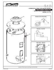
Features and ComponentsControlsContact your dealer or service agent if continued high limit switchoperation occurs.140130RESETBUTTONLEDLIGHTSFUSEFigure 1.Variable Frequency Drive (VFD)The VFD controls the speed of the combustion blower. The VFD runsthe blower at low speed during the ignition trial period and adjusts tohigh speed after ignition.I/O Module (Low and High Speed) - the I/O modules switch theVFD from low speed to high speed blower operation.Blocked Flue Switch - the blocked flue switch stops burneroperation if the exhaust outlet becomes blocked or if the burnerbecomes blocked by debris.Blower Prover Switch - the blower prover switch stops the burnerignition sequence if the blower does not operate.The Eliminator (self-cleaning system)These units include The Eliminator (Self-Cleaning System) installedin the front water inlet, see Figure 2. The Eliminator inlet tube canonly be used in the front water inlet connection. Do not install theEliminator inlet tube in either the top or back inlet water connection.The Eliminator must be oriented correctly for proper function. Thereis a marked range on the pipe nipple portion of the Eliminator, thatmust be aligned with the top of the inlet spud. A label above thejacket hole has an arrow that will point to the marked portion of thepipe nipple if the orientation is correct. If the arrow does not pointwithin the marked range on the pipe nipple, adjust the pipe nippleto correct. A pipe union is supplied with the Eliminator to reduce theprobability of misaligning the Eliminator accidentally while tighteningthe connection to the inlet water supply line. Improper orientation ofthe Eliminator can cause poor performance of the heater and cansignificantly reduce outlet water temperatures during heavy draws.Note: The Eliminator may have 1, 3 or 7 cross tubes.Figure 2.High Limit SwitchThe digital thermostat (Figure 3) contains the high limit (energycutout) switch. The high limit switch interrupts burner gas flow shouldthe water temperature reach 203°F (95°C).In the event of high limit switch operation, the water heater cannot berestarted unless the water temperature is reduced to approximately120°F (49°C). The high limit reset button on the front of the controlthen needs to be depressed.Continued manual resetting of high limit control, preceded by higher thanusual water temperature is evidence of high limit switch operation.7DIGITAL THERMOSTATFigure 3.Electronic Ignition ControlEach heater is equipped with an ignition control. The solid stateignition control (Figure 4), ignites the burner by utilizing a sparkigniter. The spark igniter shuts off during the heating cycle and theburner flame is sensed through a remote flame sensor.The ignition control will try to ignite the burner three times beforelockout. The control waits 15 minutes before trying again to ignite theburner. This is a continuous cycle.IGNITION CONTROLFigure 4.Blower/Burner AssemblyFigure 5.Attention: Do not use any portion of the Blower/Burner Assemblyas a step or support. Damage to the Blower/Burner Assembly canoccur if any portion is used as a step or support.Spark IgniterThe ignition control energizes the Spark Igniter to ignite the Burner.Intake Air ScreenThe intake air screen is attached to the inlet end of the combustionblower. Inspect the intake air screen every six months. The intake airscreen should be cleaned of any buildup of debris or foreign material.Flame SensorThe control system monitors the flame sensor to confirm that flame ispresent at the Burner. If a flame is not verified during the ignition trialperiod (4 seconds) the control system will immediately de-energizethe 24 VAC <strong>Gas</strong> Valve as indicated on the Sequence of OperationFlow Chart (Figure 24).
Installation considerationsRough In DimensionsITOP OUTLET1 1/2" NPTFTOP INLET1 1/2" NPTK1 1/2"NPTD HA CMLGEBTOP VIEWJFRONT VIEWFigure 6.BACK VIEWTable 1. Rough-In-DimensionsModel Dim.(A)BCL385T2756NOX (A)BCL385T3106NOX (A)BCL385T3666NOX (A)BCL385T3906NOXinches cm inches cm inches cm inches cmA 76 193 76 193 76 193 76 193B 16 1/4 41.2 16 1/4 41.2 16 1/4 41.2 16 1/4 41.2C 78 1/4 198.8 78 1/4 198.8 78 1/4 198.8 78 1/4 198.8D 65 3/4 167 65 3/4 167 65 3/4 167 65 3/4 167E 25 3/4 65.4 25 3/4 65.4 25 3/4 65.4 25 3/4 65.4F 21 53.3 21 53.3 21 53.3 21 53.3G 3/4 NPT 3/4 NPT 3/4 NPT 3/4 NPTH 66 1/4 168.3 66 1/4 168.3 66 1/4 168.3 66 1/4 168.3I 6 15.2 6 15.2 6 15.2 6 15.2J 27 3/4 70.5 27 3/4 70.5 27 3/4 70.5 27 3/4 70.5K 1 1/2 NPT 1 1/2 NPT 1 1/2 NPT 1 1/2 NPTL 1 1/2 NPT 1 1/2 NPT 1 1/2 NPT 1 1/2 NPTM 41 <strong>104</strong> 41 <strong>104</strong> 41 <strong>104</strong> 41 <strong>104</strong>Approx. Shipping Weight STD 850 lbs. 386 Kg. 850 lbs. 386 Kg. 850 lbs. 386 Kg. 850 lbs. 386 Kg.Approx. Shipping Weight ASME 900 lbs. 408 Kg. 900 lbs. 408 Kg. 900 lbs. 408 Kg. 900 lbs. 408 Kg.Table 2. Recovery Capacities, based on 82% Thermal efficiency(A)BCL385T2756NOX(A)BCL385T3106NOX(A)BCL385T3666NOX(A)BCL385T3906NOXInputBTUHInputKWU.S.Gal.Liters Eff. %U. S. Gallons/Hr. and Liters/Hr. at Temperature Rise Indicated°F 36 40 50 54 60 70 72 80 90 100 108 110 120 126 130 140°C 20 22 28 30 33 39 40 44 50 56 60 61 67 70 72 78275000 85 82 GPH 754 678 543 502 452 388 377 339 301 271 251 247 226 215 209 19481 322 LPH 2853 2567 2054 1902 1712 1467 1426 1284 1141 1027 951 934 856 815 790 734310000 85 82 GPH 849 765 612 566 510 437 425 382 340 306 283 278 255 243 235 21891 322 LPH 3216 2894 2315 2144 1929 1654 1608 1447 1286 1158 1072 1052 965 919 890 827366000 85 82 GPH 1003 903 722 669 602 516 501 451 401 361 334 328 301 287 278 258107 322 LPH 3797 3417 2734 2531 2278 1953 1898 1708 1519 1367 1266 1243 1139 1085 1051 976390000 85 82 GPH 1069 962 769 712 641 550 534 481 427 385 356 350 321 305 296 275114 322 LPH 4046 3641 2913 2697 2427 2081 2023 1820 1618 1456 1349 1324 1214 1156 1120 <strong>104</strong>0Table 3. <strong>Gas</strong> and Electrical CharacteristicsModel<strong>Gas</strong> Type<strong>Gas</strong> Supply PressureMinimumMaximumVolts / HzAll Models Natural 3.5" W.C. (0.87 kPa) 14" W.C. (3.48 kPa) 120/60
TEMPERED WATEROUTLETHOT WATEROUTLET12” TO 15”(30-38 cm)expansion. Contact a local plumbing service agency to have athermal expansion tank installed.See <strong>Water</strong> Line Connections on page 20 and <strong>Water</strong> PipingDiagrams on page 34.Temperature-Pressure Relief ValveCOLDWATERINLETCHECKVALVETO TANKINLETFigure 10.Dishwashing MachinesMIXINGVALVECHECKVALVEAll dishwashing machines meeting the National SanitationFoundation requirements are designed to operate with waterflow pressures between 15 and 25 pounds per square inch(103 kPa and 173 kPa). Flow pressures above 25 poundsper square inch (173 kPa), or below 15 pounds per squareinch (103 kPa), will result in improperly sanitized dishes.Where pressures are high, a water pressure reducing or flowregulating control valve should be used in the 180°F (82°C)line to the dishwashing machine and should be adjusted todeliver water pressure between these limits.The National Sanitation Foundation also recommends circulationof 180°F (82°C) water. The circulation should be just enoughto provide 180°F (82°C) water at the point of take-off to thedishwashing machine.Adjust flow by throttling a full port ball valve installed in thecirculating line on the outlet side of the pump. Never throttle flowon the suction side of a pump. See <strong>Water</strong> Piping Diagrams inthis manual.Closed <strong>Water</strong> Systems<strong>Water</strong> supply systems may, because of code requirementsor such conditions as high line pressure, among others, haveinstalled devices such as pressure reducing valves, checkvalves, and back flow preventers. Devices such as these causethe water system to be a closed system.Thermal ExpansionAs water is heated, it expands (thermal expansion). In a closedsystem the volume of water will grow when it is heated. As thevolume of water grows there will be a corresponding increasein water pressure due to thermal expansion. Thermal expansioncan cause premature tank failure (leakage). This type of failureis not covered under the limited warranty. Thermal expansioncan also cause intermittent Temperature-Pressure Relief Valveoperation: water discharged from the valve due to excessivepressure build up. This condition is not covered under the limitedwarranty. The Temperature-Pressure Relief Valve is not intendedfor the constant relief of thermal expansion.A properly sized thermal expansion tank must be installed onall closed systems to control the harmful effects of thermalExplosion HazardTemperature-Pressure Relief Valvemust comply with ANSI Z21.22-CSA 4.4 and ASME code.Properly sized temperaturepressurerelief valve must beinstalled in opening provided.Can result in overheating andexcessive tank pressure.Can cause serious injury or death.This water heater is provided with a properly rated/sized andcertified combination Temperature-Pressure Relief Valve (T&Pvalve) by the manufacturer. The valve is certified by a nationallyrecognized testing laboratory that maintains periodic inspectionof production of listed equipment of materials as meeting therequirements for Relief Valves for Hot <strong>Water</strong> Supply Systems,ANSI Z21.22 • CSA 4.4, and the code requirements of ASME.If replaced, the new T&P valve must meet the requirementsof local codes, but not less than a combination Temperature-Pressure Relief Valve rated/sized and certified as indicated inthe above paragraph. The new valve must be marked with amaximum set pressure not to exceed the marked hydrostaticworking pressure of the water heater (150 psi = 1,035 kPa) anda discharge capacity not less than the water heater Btu/hr or kWinput rate as shown on the water heater’s model rating label.NOTE: In addition to the factory installed Temperature-PressureRelief Valve on the water heater, each remote storage tank thatmay be installed and piped to a water heating appliance must alsohave its own properly sized, rated and approved Temperature-Pressure Relief Valve installed. Call the toll free technicalsupport phone number listed on the back cover of this manualfor technical assistance in sizing a Temperature-Pressure ReliefValve for remote storage tanks.For safe operation of the water heater, the Temperature-PressureRelief Valve must not be removed from its designated openingnor plugged. The Temperature-Pressure Relief Valve must beinstalled directly into the fitting of the water heater designed for therelief valve. Install discharge piping so that any discharge will exitthe pipe within 6 inches (15.2 cm) above an adequate floor drain,or external to the building. In cold climates it is recommendedthat it be terminated at an adequate drain inside the building. Becertain that no contact is made with any live electrical part. Thedischarge opening must not be blocked or reduced in size underany circumstances. Excessive length, over 30 feet (9.14 m), oruse of more than four elbows can cause restriction and reducethe discharge capacity of the valve.13
No valve or other obstruction is to be placed between theTemperature-Pressure Relief Valve and the tank. Do not connectdischarge piping directly to the drain unless a 6” (15.2 cm)air gap is provided. To prevent bodily injury, hazard to life, orproperty damage, the relief valve must be allowed to dischargewater in adequate quantities should circumstances demand. Ifthe discharge pipe is not connected to a drain or other suitablemeans, the water flow may cause property damage.CAUTION<strong>Water</strong> Damage Hazard• Temperature-Pressure Relief Valve dischargepipe must terminate at adequate drain.T&P Valve Discharge Pipe Requirements:• Shall not be smaller in size than the outlet pipe size of thevalve, or have any reducing couplings or other restrictions.• Shall not be plugged or blocked.• Shall not be exposed to freezing temperatures.• Shall be of material listed for hot water distribution.• Shall be installed so as to allow complete drainage of boththe Temperature-Pressure Relief Valve and the dischargepipe.• Must terminate a maximum of six inches above a floordrain or external to the building. In cold climates, it isrecommended that the discharge pipe be terminated at anadequate drain inside the building.• Shall not have any valve or other obstruction between therelief valve and the drain.Burn hazard.Hot water discharge.Keep clear of Temperature-Pressure Relief Valvedischarge outlet.The Temperature-Pressure Relief Valve must be manuallyoperated at least twice a year. Caution should be taken toensure that (1) no one is in front of or around the outlet of theTemperature-Pressure Relief Valve discharge line, and (2) thewater manually discharged will not cause any bodily injury orproperty damage because the water may be extremely hot. Ifafter manually operating the valve, it fails to completely resetand continues to release water, immediately close the cold waterinlet to the water heater, follow the draining instructions in thismanual, and replace the Temperature-Pressure Relief Valve witha properly rated/sized new one.NOTE: The purpose of a Temperature-Pressure Relief Valve isto prevent excessive temperatures and pressures in the storagetank. The T&P valve is not intended for the constant relief ofthermal expansion. A properly sized thermal expansion tank mustbe installed on all closed systems to control thermal expansion,see Closed <strong>Water</strong> Systems and Thermal Expansion on page 13.If you do not understand these instructions or have any questionsregarding the Temperature-Pressure Relief Valve call the toll freenumber listed on the back cover of this manual for technicalassistance.Combustible Material StorageFire or Explosion HazardDo not store or use gasoline or other flammable vapors andliquids in the vicinity of this or any other appliance.Avoid all ignition sources if you smell gas.Do not expose water heater controls to excessive gaspressure.Use only the gas shown on the water heater rating label.Maintain required clearances to combustibles.Keep ignition sources away from faucets after extendedperiods of non-use.Read instruction manual beforeinstalling, using or servicingwater heater.Keep water heater area clear and free of combustible materials,gasoline and other flammable vapors and liquids.Contaminated AirBreathing Hazard - Carbon Monoxide <strong>Gas</strong>Install water heater in accordance withthe Instruction Manual and NFPA 54 orCAN/CSA-B149.1.To avoid injury, combustion and ventilationair must be taken from outdoors.Do not place chemical vapor emittingproducts near water heater.Breathing carbon monoxide can cause brain damage ordeath. Always read and understand instruction manual.Corrosion of the flue ways and vent system may occur if air forcombustion contains certain chemical vapors. Such corrosionmay result in failure and risk of asphyxiation.Combustion air that is contaminated can greatly diminish the lifespan of the water heater and water heater components such ashot surface igniters and burners. Propellants of aerosol sprays,beauty shop supplies, water softener chemicals and chemicalsused in dry cleaning processes that are present in the combustion,ventilation or ambient air can cause such damage.Do not store products of this sort near the water heater. Air whichis brought in contact with the water heater should not contain anyof these chemicals. If necessary, uncontaminated air should beobtained from remote or outdoor sources. The limited warrantyis voided when failure of water heater is due to a corrosiveatmosphere. (See limited warranty for complete terms andconditions).14
Air RequirementsBreathing Hazard - Carbon Monoxide <strong>Gas</strong>Install water heater in accordance withthe Instruction Manual and NFPA 54 orCAN/CSA-B149.1.To avoid injury, combustion and ventilationair must be taken from outdoors.Do not place chemical vapor emittingproducts near water heater.Breathing carbon monoxide can cause brain damage ordeath. Always read and understand instruction manual.For safe operation an adequate supply of fresh uncontaminatedair for combustion and ventilation must be provided.An insufficient supply of air can cause recirculation of combustionproducts resulting in contamination that may be hazardous tolife. Such a condition often will result in a yellow, luminous burnerflame, causing sooting of the combustion chamber, burners andflue tubes and creates a risk of asphyxiation.Do not install the water heater in a confined space unless anadequate supply of air for combustion and ventilation is broughtin to that space using the methods described in the ConfinedSpace section that follows.Never obstruct the flow of ventilation air. If you have any doubtsor questions at all, call your gas supplier. Failure to provide theproper amount of combustion air can result in a fire or explosionand cause property damage, serious bodily injury or death.Unconfined SpaceAn Unconfined Space is one whose volume IS NOT LESS THAN50 cubic feet per 1,000 Btu/hr (4.8 cubic meters per kW) of thetotal input rating of all appliances installed in the space. Roomscommunicating directly with the space, in which the appliancesare installed, through openings not furnished with doors, areconsidered a part of the unconfined space.Makeup air requirements for the operation of exhaust fans,kitchen ventilation systems, clothes dryers and fireplaces shallalso be considered in determining the adequacy of a space toprovide combustion, ventilation and dilution air.Unusually Tight ConstructionIn unconfined spaces in buildings, infiltration may be adequateto provide air for combustion, ventilation and dilution of fluegases. However, in buildings of unusually tight construction (forexample, weather stripping, heavily insulated, caulked, vaporbarrier, etc.) additional air must be provided using the methodsdescribed in the Confined Space section that follows.Confined SpaceA Confined Space is one whose volume IS LESS THAN 50 cubicfeet per 1,000 Btu/hr (4.8 cubic meters per kW) of the total inputrating of all appliances installed in the space.Openings must be installed to provide fresh air for combustion,ventilation and dilution in confined spaces. The required size forthe openings is dependent on the method used to provide freshair to the confined space AND the total Btu/hr input rating of allappliances installed in the space.Exhaust FansWhere exhaust fans are installed, additional air shall be providedto replace the exhausted air. When an exhaust fan is installedin the same space with a water heater, sufficient openings toprovide fresh air must be provided that accommodate therequirements for all appliances in the room and the exhaust fan.Undersized openings will cause air to be drawn into the roomthrough the water heater’s vent system causing poor combustion.Sooting, serious damage to the water heater and the risk of fireor explosion may result. It can also create a risk of asphyxiation.Louvers and GrillesThe free areas of the fresh air openings in the instructions thatfollow do not take in to account the presence of louvers, grilles orscreens in the openings.The required size of openings for combustion, ventilation anddilution air shall be based on the “net free area” of each opening.Where the free area through a design of louver or grille or screenis known, it shall be used in calculating the size of openingrequired to provide the free area specified. Where the louver andgrille design and free area are not known, it shall be assumedthat wood louvers will have 25% free area and metal louvers andgrilles will have 75% free area. Non motorized louvers and grillesshall be fixed in the open position.VentingTHE INSTRUCTIONS IN THIS SECTION ON VENTING MUSTBE FOLLOWED TO AVOID CHOKED COMBUSTION ORRECIRCULATION OF FLUE GASES. SUCH CONDITIONS CAUSESOOTING OR RISKS OF FIRE AND ASPHYXIATION.This heater is not approved for direct vent installation.Heater must be protected from freezing downdrafts.Remove all soot or other obstructions from the chimney that willretard a free draft.Type B venting is required with these heaters. For typical ventingapplication see TECHNICAL DATA VENTING on pages 18 and 19.This water heater must be vented in compliance with all local codes,the current revision of the National Fuel <strong>Gas</strong> Code (ANSI-Z223.1)and with the Category I Venting Tables.VENTING INSTALLATIONIf any part of the vent system is exposed to ambient temperaturesbelow 40°F (4.4°C) it must be insulated to prevent condensation.15• Do not connect the heater to a common vent or chimney withsolid fuel burning equipment. This practice is prohibited bymany local building codes as is the practice of venting gasfired equipment to the duct work of ventilation systems.Figure 11. figure 12.• Where a separate vent connection is not available and the ventpipe from the heater must be connected to a common vent withan oil burning furnace, the vent pipe should enter the smallercommon vent or chimney at a point above the large vent pipe.
Multiple Heater ManifoldOutdoor Air Through One OpeningFigure 13 and tables on pages 18 and 19 should be used forhorizontally manifolding two or more heaters.Figure 13.Fresh Air Openings for Confined SpacesThe following instructions shall be used to calculate the size,number and placement of openings providing fresh air forcombustion, ventilation and dilution in confined spaces. Theillustrations shown in this section of the manual are a referencefor the openings that provide fresh air into confined spacesonly. DO NOT refer to these illustrations for the purpose of ventinstallation. See Venting Installation on page 15 for completeventing installation instructions.Outdoor Air Through Two OpeningsFigure 15.Alternatively a single permanent opening, commencing within 12inches (300 mm) of the top of the enclosure, shall be provided.See Figure 14. The water heater shall have clearances of atleast 1 inch (25 mm) from the sides and back and 6 inches (150mm) from the front of the water heater. The opening shall directlycommunicate with the outdoors or shall communicate through avertical or horizontal duct to the outdoors or spaces that freelycommunicate with the outdoors and shall have a minimum freearea of the following:1. 1 square inch per 3000 Btu/hr (733 mm 2 per kW) of the total input ratingof all appliances located in the enclosure, and2. Not less than the sum of the areas of all vent connectors in the space.Outdoor Air Through Two Horizontal DuctsFigure 14.The confined space shall be provided with two permanentopenings, one commencing within 12 inches (300 mm) of the topand one commencing within 12 inches (300 mm) of the bottom ofthe enclosure. The openings shall communicate directly with theoutdoors. See Figure 14.Each opening shall have a minimum free area of 1 square inchper 4,000 Btu/hr (550 mm2 per kW) of the aggregate input ratingof all appliances installed in the enclosure. Each opening shallnot be less than 100 square inches (645 cm2).16Figure 16.The confined space shall be provided with two permanenthorizontal ducts, one commencing within 12 inches (300 mm) ofthe top and one commencing within 12 inches (300 mm) of thebottom of the enclosure. The horizontal ducts shall communicatedirectly with the outdoors. See Figure 16.Each duct opening shall have a minimum free area of 1 squareinch per 2,000 Btu/hr (1100 mm2 per kW) of the aggregate inputrating of all appliances installed in the enclosure.When ducts are used, they shall be of the same cross sectionalarea as the free area of the openings to which they connect.The minimum dimension of rectangular air ducts shall be not lessthan 3 inches (7.6 cm).
Table 6. TECHNICAL DATA VENTINGTYPE B GAS VENTMultiple <strong>Gas</strong> Fired Tank-Type <strong>Heaters</strong>When venting multiple tank type heaters using Type B ventpipe, follow the installation diagram (figure 13) and tablesbelow which give sizing and data based upon NFPA 54/ANSIZ223. 2006.Model (A)BCL385T2756NOXInput: 275,000 btu/hrTotal Vent Height (Feet)Vent connector size: 6 inches 6 8 10 15 20 30 50 100Input (btu/hr) Rise Vent Connector Diameter (Inches)275,000 1 Ft. 8 8 8 7 7 6 6 6275,000 2 Ft. 8 8 7 7 7 6 6 6275,000 3 Ft. 7 7 7 7 7 6 6 6Number of <strong>Heaters</strong> Combined Input (btu/hr) Manifold and Common Vent Diameter (Inches)2 550,000 10 10 9 9 8 8 7 73 825,000 14 12 12 10 10 9 9 84 1,100,000 14 14 14 12 12 12 10 9Model (A)BCL385T3106NOXInput: 310,000 btu/hrTotal Vent Height (Feet)Vent connector size: 6 inches 6 8 10 15 20 30 50 100Input (btu/hr) Rise Vent Connector Diameter (Inches)310,000 1 Ft. - 8 8 8 7 7 6 6310,000 2 Ft. 8 8 8 7 7 7 6 6310,000 3 Ft. 8 8 8 7 7 7 6 6Number of <strong>Heaters</strong> Combined Input (btu/hr) Manifold and Common Vent Diameter (Inches)2 620,000 12 10 10 9 9 8 8 73 930,000 14 14 12 12 10 10 9 94 1,240,000 16 14 14 14 12 12 10 9Model (A)BCL385T3666NOXInput: 366,000 btu/hrTotal Vent Height (Feet)Vent connector size: 6 inches 6 8 10 15 20 30 50 100Input (btu/hr) Rise Vent Connector Diameter (Inches)366,000 1 Ft. - - - 8 8 7 7 6366,000 2 Ft. - - 8 8 8 7 7 6366,000 3 Ft. - 8 8 8 7 7 6 6Number of <strong>Heaters</strong> Combined Input (btu/hr) Manifold and Common Vent Diameter (Inches)2 732,000 12 12 12 10 9 9 8 83 1,098,000 14 14 14 12 12 12 10 94 1,464,000 16 16 16 14 14 12 12 1018
Table 7. TECHNICAL DATA VENTING (Continued)Model (A)BCL385T3906NOXInput: 390,000 btu/hrTotal Vent Height (Feet)Vent connector size: 6 inches 6 8 10 15 20 30 50 100Input (btu/hr) Rise Vent Connector Diameter (Inches)390,000 1 Ft. - - - - 8 7 7 6390,000 2 Ft. - - - 8 8 7 7 6390,000 3 Ft. - - 8 8 8 7 7 6Number of <strong>Heaters</strong> Combined Input (btu/hr) Manifold and Common Vent Diameter (Inches)2 780,000 12 12 12 10 10 9 9 83 1,170,000 16 14 14 14 12 12 10 94 1,560,000 16 16 16 14 14 14 12 1019
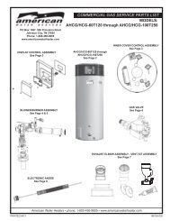
Heater WiringAll electrical work must be installed in accordance with the latest version of the National Electrical Code ANSI/NFPA No. 70 andmust conform to all local code authority having jurisdiction. AN ELECTRICAL GROUND IS REQUIRED TO REDUCE RISK OFELECTRICAL SHOCK OR POSSIBLE ELECTROCUTION.The controls of this water heater are polarity sensitive. Be certain to properly wire the hot and neutral connections.UPPERPROBELOWERPROBE11E79THERMOSTATIGNITION CONTROLLERFENWAL 35-63 TH/WV1/PV1IND/MV1R-24vacHEAT CALLBKPROVER PSNOGASVALVEBLOCKEDFLUE PSNCGR-HIGH SPEEDRW/GR-24vacHEAT CALLW/GW/GRW/G4 WIRES2 WIRESE3-2 E3-1E1-4E3-4 E3-3E1-3E1-2E1-1 E4-2E4-1E2-1E2-2BK-SWITCHED HOTW-NEUTRALFC+FC-V2GNDS1H.V.WIGNITIONCABLEW/GO345345IO MODULELOWIO MODULEHIGH2121SWITCHBKWBK - BLACKBR - BROWNR - REDY - YELLOWG - GREENBL - BLUEW - WHITEV - VIOLETO - ORANGEGR - GRAYIGNITERW/GFLAMERODIF ANY OF THE ORIGINAL WIRE AS SUPPLIED MUST BE REPLACED USE ONLY 18 AWG 105°C 600V UL AWM STYLE #1015 WIREEXCEPT GAS VALVE CABLE WHICH MUST USE 2 CONDUCTOR 18 AWG 80°C 300V UL CATAGORY QPTZ POWER LIMITED CIRCUIT CABLE.GRW/BK4.7k 4.7kRCOMLI1LI224VBKVFDU V WWBLOWERL1L2GNDRGGBKW120VAC/60HzNEUTRALGROUNDFACTORY INSTALLEDBY INSTALLERFigure 20.22
<strong>Gas</strong> PipingContact your local gas service company to ensure that adequategas service is available and to review applicable installation codesfor your area.Size the main gas line in accordance with Table 8. The figures shownare for straight lengths of pipe at 0.5 in. W.C. pressure drop, which isconsidered normal for low pressure systems. Note: Fittings such aselbows, tees and line regulators will add to the pipe pressure drop.Also refer to the latest version of the National Fuel <strong>Gas</strong> Code.Schedule 40 Steel or Wrought Iron Pipe is the preferred materialfor the gas line of this water heater. It is imperative to follow thesizing recommendations in the latest version of the National Fuel<strong>Gas</strong> Code if Corrugated Stainless Steel Tubing (CSST) is used asthe gas line for this water heater.The heater is not intended for operation at higher than 14.0" W.C.-natural gas, (1/2 pound per square inch gage) supply gas pressure.Exposure to higher supply pressure may cause damage to thegas valve which could result in fire or explosion. If overpressurehas occurred such as through improper testing of gas lines oremergency malfunction of the supply system, the gas valve must bechecked for safe operation. Make sure that the outside vents on thesupply regulators and the safety vent valves are protected againstblockage. These are parts of the gas supply system, not the heater.Vent blockage may occur during ice storms.Table 8 - GAS SUPPLY PIPE LENGTHS (IN FEET)Maximum Equivalent Pipe Length - Natural <strong>Gas</strong> OnlyInput rateSchedule 40 Steel or Wrought Iron Pipe(BTU/HR) 1/2" 3/4" 1" 1 1/4" 1 1/2"120,000 20 70 200 200 200154,000 10 40 150 200 200180,000 - 30 100 200 200199,000 - 30 90 200 200250,000 - 20 60 200 200275,000 - 10 50 200 200310,000 - 10 40 150 200366,000 - - 30 100 200390,000 - - 20 100 200Fitting Type*Equivalent length in feet45°Ell 0.7 1.0 1.2 1.6 1.990°Ell 1.6 2.1 2.6 3.5 4.0Tee 3.1 4.1 5.2 6.9 8.0Natural <strong>Gas</strong> 0.60 Specific Gravity, 0.50" W.C. Pressure Drop*Screwed FittingsIt is important to guard against gas valve fouling from contaminantsin the gas ways. Such fouling may cause improper operation, fireor explosion.If copper supply lines are used they must be internally tinned andcertified for gas service. Before attaching the gas line, be sure thatall gas pipe is clean on the inside.To trap any dirt or foreign material in the gas supply line, asediment trap must be incorporated in the piping (see Figure 21).The sediment trap must be readily accessible and not subject tofreezing conditions. Install in accordance with recommendations ofserving gas suppliers. Refer to the latest version of the NationalFuel <strong>Gas</strong> Code.To prevent damage, care must be taken not to apply too muchtorque when attaching gas supply pipe to gas valve inlet.Apply joint compounds (pipe dope) sparingly and only to themale threads of pipe joints. Do not apply compounds to the firsttwo threads. Use compounds resistant to the action of liquefiedpetroleum gases.<strong>Gas</strong> Meter Size – Natural <strong>Gas</strong>es OnlyBe sure the gas meter has sufficient capacity to supply the full ratedgas input of the water heater as well as the requirements of all othergas fired equipment supplied by the meter. If gas meter is too small, askthe gas company to install a larger meter having adequate capacity.GAS PIPING AND SEDIMENT TRAP INSTALLATION<strong>Gas</strong> Line Leak TestingFigure 21.Fire and Explosion HazardUse joint compound or Teflon tapecompatible with propane gas.Leak test before placing the waterheater in operation.Disconnect gas piping and main gasshutoff valve before leak testing.Install sediment trap in accordancewith NFPA 54.Any time work is done on the gas supply system perform a leak testto avoid the possibility of fire or explosion.1. For test pressures exceeding 1/2 psi (3.45 kPa) disconnect thewater heater and its Main <strong>Gas</strong> Shutoff Valve from the gas supplypiping system during testing, see Figure 21. The gas supply linemust be capped when disconnected from the water heater.2. For test pressures of 1/2 psi (3.45 kpa) or less, the water heaterneed not be disconnected, but must be isolated from the supplygas line by closing the Main <strong>Gas</strong> Shutoff Valve during testing.3. Coat all supply gas line joints and connections upstream of thewater heater with a non-corrosive soap and water solution totest for leaks. Bubbles indicate a gas leak. Do not use matches,candles, flame or other sources of ignition for this purpose.4. Repair any leaks before placing the water heater in operation.Purging<strong>Gas</strong> line purging is required with new piping or systems in which airhas entered.Purging should be performed per the current edition of NFPA 54 theNational Fuel <strong>Gas</strong> Code.23
Start upPrior to Start UpInstallation and start up of this water heater requires abilitiesand skills equivalent to that of a licensed tradesman in the fieldinvolved, see Qualifications on page 6.Do not place the water heater in operation if any part has beenunder water. Immediately call a qualified service technician toinspect the water heater and to replace any part of the controlsystem and any gas control which has been under water.Light the water heater in accordance with the Lighting andOperation Instruction label on the water heater and in this manualon page 26.The water heaters covered by this manual are equipped withan electronic control system that automatically sequences theBlower, the Igniter, the 24 VAC <strong>Gas</strong> Valve, Burner ignition,and flame sensing. The control system will lock out after threeunsuccessful ignition attempts.Before attempting start up, thoroughly study and familiarizeyourself with the exact Sequence Of Operation, see the writtenSequence Of Operation on page 26 and the Sequence OfOperation Flow Chart on page 27.Be certain that the water heater is full of water, that air is purgedfrom the gas and water lines and that there are no leaks in thegas and water lines. Ensure all inlet water valves are open.Filling The <strong>Water</strong> HeaterFollow these steps to fill the water heater prior to start up.1. Close the heater drain valve.2. Open a nearby hot water faucet to permit the air in the systemto escape.3. Fully open the cold water inlet valve allowing the piping andwater heater to fill with water.4. Close the hot water faucet opened in Step 2 as water starts to flow.Supply <strong>Gas</strong> Line PurgingFire or Explosion Hazard<strong>Gas</strong> line purging is required with new piping or systems inwhich air has entered.To avoid risk of fire or explosion purge discharge must notenter into confined areas or spaces where ignition can occur.The area must be well ventilated and all sources of ignitionmust be deactivated or removed.Use only the gas shown on the water heater rating label.Keep ignition sources away from faucets after extendedperiods of non-use.Initial Start UpRequired Test EquipmentU-tube manometer, pressure gauge, or digital manometer.Recommended range: 20” W.C. (5 kPa).Note: All test equipment must be acclimated to ambienttemperature before calibration and use.Preparation1. Adjust the thermostat to the lowest temperature setting.2. Turn the water heater’s on/off switch to the “off” position.3. Close the Main <strong>Gas</strong> Shut Off Valve, see Figure 21 on page 23.4. Wait five (5) minutes for any residual gas to clear.5. Open the Supply <strong>Gas</strong> Pressure Port on the gas valve by turningthe center screw counter-clockwise. Connect the manometerto the supply gas pressure test port, see Figure 22 on page 25.6. Open the Main <strong>Gas</strong> Shutoff Valve.7. Measure and record the supply gas pressure, this is a “static”supply gas pressure reading; while the water heater is not firing.Figure 22. – Top ViewLighting The <strong>Water</strong> Heater1. Turn the water heater’s on/off switch to the “on” position.2. Adjust the thermostat to the desired water temperature.3. Record the supply gas pressure when the 24 VAC <strong>Gas</strong> Valve isenergized and the Burner is operating. This is a “dynamic” gaspressure reading; while the water heater is firing.4. Compare the actual supply gas pressure reading recordedabove to the required minimum/maximum values given inTable 3 on page 8. Adjust supply gas pressure as necessary,see the instructions that follow.5. After the supply gas pressure adjustments are complete, turnoff the water heater and close the Main <strong>Gas</strong> Supply ShutOff Valve. Disconnect the manometer from the Supply <strong>Gas</strong>Pressure Port and turn the center screw clockwise until theport is closed.Supply <strong>Gas</strong> Pressure AdjustmentRead instruction manual beforeinstalling, using or servicingwater heater.1. Close the Main <strong>Gas</strong> Shutoff Valve, see Figure 21 on page 23.2. Purge all air from the supply gas line up to the water heater’sMain <strong>Gas</strong> Shutoff Valve.3. When all air has been purged from the supply gas line, tightenall supply gas line connections.4. Check for gas leaks, see <strong>Gas</strong> Line Leak Testing on page 23and repair any leaks found.24Fire and Explosion HazardDo not use water heater with any gasother than the gas shown on the ratinglabel.Excessive gas pressure to gas valve cancause serious injury or death.Turn off gas lines during installation.Contact a qualified installer or serviceagency for installation and service.
Supply gas pressure shall be measured while the water heateris not firing (static pressure) and while the water heater is firingat full capacity (dynamic pressure).If the supply gas pressure to the water heater is not betweenthe required minimum and maximum values given in Table 3on page 8 adjust the supply gas regulator as necessary. Adjustthe supply gas regulator(s) per the regulator manufacturer’sinstructions to achieve the required “static” and “dynamic”supply gas pressure.Multiple Appliance Installations:In multiple water heater installations or in installations wherethe installed water heater(s) share a common gas supply mainwith other gas fired appliances; the supply gas pressures shallbe measured at each water heater with all gas fired appliancesconnected to a common main firing at full capacity.On multiple water heater installations the supply gas line regulatorsshall be adjusted to provide gas pressure to each water heaterwithin the minimum and maximum supply pressure requirementslisted in Table 3 on page 8 with all gas fired appliances connectedto a common gas main firing at full capacity.Note: A pressure drop of more than 1.5” W. C. (0.37 kPa)when the Main Burner ignites is an indication of an inadequatesupply of gas and can lead to ignition failure, rough starts and/or rough operation. If a drop of more than 1.5” W. C. (0.37 kPa)in supply gas pressure occurs when the Main Burner ignites,ensure the supply gas lines and regulator(s) are properly sizedand installed. See the requirements for Supply <strong>Gas</strong> Regulatoron page 12 and <strong>Gas</strong> Piping on page 23. Ensure all requirementsand installation instructions are maintained.Checking VentingThe following steps shall be followed with each applianceconnected to the venting system placed in operation, while anyother appliances connected to the venting system are not inoperation.1. Seal any unused openings in the venting system.2. Inspect the venting system for proper size and horizontal pitch, asrequired in the National Fuel <strong>Gas</strong> Code, ANSI Z223.1or the CAN/CGA B149 Installation Codes and these instructions. Determinethat there is no blockage or restriction, leakage, corrosion andother deficiencies which could cause an unsafe condition.3. So far as is practical, close all building doors and windowsand all doors between the space in which the water heater(s)connected to the venting system are located and other spacesof the building. Turn on all appliances not connected to theventing system. Turn on all exhaust fans, such as range hoodsand bathroom exhausts, so they shall operate at maximumspeed. Close fireplace dampers.4. Follow the lighting instruction. Place the water heater beinginspected in operation. Adjust thermostat so the water heatershall operate continuously.5. Inspect vent system for leakage after 5 minutes of main burneroperation.6. After it has been determined that each appliance connectedto the venting system properly vents when tested as outlinedabove, return doors, windows, exhaust fans, fireplacedampers and any other gas burning appliance to their previousconditions of use.7. If improper venting is observed during any of the above tests,the venting system must be corrected.FAILURE TO CORRECT BACK DRAFTS MAY CAUSE AIRCONTAMINATION AND UNSAFE CONDITIONS.• If the back draft cannot be corrected by the normal method orif a suitable draft cannot be obtained, a blower type flue gasexhauster must be employed to assure proper venting andcorrect combustion.Checking the InputFollow these instructions to determine the firing rate of the waterheater.1. Follow the procedure described in the "Initial Start Up" sectionon page 24 to measure the static and dynamic supply gaspressures. Verify that the static and dynamic supply gaspressures conform to the values listed in Table 3 on page 8.2. Use this formula to “clock” the meter. Be sure that other gasconsuming appliances are not operating during this interval.(3600/T) x H = BtuhT = Time in seconds to burn one cubic foot of gas.H = Btu’s per cubic foot of gas.Btuh = Actual heater input.Example:T = 13.1 secondsH = 1000 BTU/Cu.Ft.Btuh = (3,600/13.1) x 1,000 = 275,000UNDER NO CIRCUMSTANCES SHOULD THE GAS INPUT EXCEEDTHE INPUT SHOWN ON THE HEATER'S RATING PLATE.<strong>Water</strong> Temperature Adjustment<strong>Water</strong> temperature over 125°F (52°C)can cause severe burns instantlyresulting in severe injury or death.Children, the elderly and thephysically or mentally disabled are athighest risk for scald injury.Feel water before bathing orshowering.Temperature limiting devices such asmixing valves must be installedwhen required by codes and toensure safe temperatures at fixtures.The water temperature is controlled by a thermostat, Fig. 3,which has two sensing elements. One sensor is located near thetop of the tank and the other is near the center. The thermostatis set in the lowest position before the heater leaves the factory.The thermostat temperature dial, Fig. 3, is accessible byremoving the control box cover. The dial is adjustable and maybe set for 120°F (49°C) to 180°F (82°C) water temperature, but120°F (49°C) is the recommended starting point. It is suggestedthe dial be placed on the lowest setting which produces anacceptable hot water supply. This will always give the mostenergy efficient operation. The temperature control has a 4°Ffixed differential.25
The following information will describe the Sequence of Operationfor this water heater.1. Switch power on to unit.2. Thermostat calls for heat.3. Variable Frequency Drive sends power to Blower.4. Combustion Blower initiates air flow through water heater closingthe Prover Switch.5. Blower runs at low speed for 30 second pre-purge.6. The Ignition Control provides power to the Spark Igniter andopens the <strong>Gas</strong> Valve.7. Ignition Control maintains spark for up to 4 seconds and monitorsFlame Sensor to determine if Burner is lit.Lighting & Operating LabelA.Sequence of Operation8. If the Flame Sensor does not detect a strong enough flame, theIgnition Control shuts off the <strong>Gas</strong> Valve and allows the Blower topurge the unit for 30 seconds. At that time, the Ignition Controlrestarts with step 6. It will try and ignite the main burners 2 moretimes. If the unit does not light, the Ignition Control will wait 15minutes and then restart at step 6. This cycle will continue untilthe unit lights or the power is shutoff to the unit.9. If the Flame Sensor detects a strong flame, the Ignition Controlwill allow the unit to operate until the thermostat is satisfied.10. Once the unit is satisfied, the Thermostat will shut off the Blower,<strong>Gas</strong> Valve and Ignition Control and the unit will be in standbymode until another call for heat is initiated by the thermostat.See the flow chart on page 27 for more detailed information.FOR YOUR SAFETY READ BEFORE OPERATINGWARNING: If you do not follow these instructions exactly, a fire orexplosion may result causing property damage, personal injuryor loss of life.BEFORE OPERATING: ENTIRE SYSTEM MUST BE FILLED WITH WATER AND AIR PURGED FROM ALL LINES.This appliance does not have a pilot. It is equipped withan ignition device which automatically lights the burner.Do not try to light the burner by hand.B. BEFORE OPERATING smell all aroung the area for gas.Be sure to smell next to the floor because some gas isheavier than air and will settle on the floor.WHAT TO DO IF YOU SMELL GASDo not try to light any appliance.Do not touch any electric switch;do not use any phone in your building.Immediately call your gas supplier from a neighbor'sphone. Follow the gas suppliers instructions.1. STOP! Read the safety informationabove on this label.2. Set the ON/OFF switch on the control box tothe “OFF” position.3. Set the thermostat to the lowest setting.4. This appliance is equipped with a device whichautomatically lights the burner.DO NOT TRY TO LIGHT THE BUNER BY HAND.5. Wait five (5) minutes to clear out any gas.If you then smell gas, STOP! Follow “B”in the safety information above on this label. Ifyou don’t smell gas, go to the next step.6. Turn on all electrical power to the appliance.OPERATING INSTRUCTIONSFLAMMABLEIf you cannot reach your gas supplier, call the firedepartment.C. Use only your hand to push the control buttons. Never usetools. If the control buttons will not push in, don’t try torepair them, call a qualified service technician. Force orattempted repair may result in a fire or explosion.D. Do not use this appliance if any part has been under water.Immediately contact a qualified installer or service agencyto replace a flooded water heater. Do not attempt to repairthe unit. It must be replaced!8. Set the thermostat to the desired setting.CAUTION: Hotter water increases the riskof scald injury. Consult the instructionmanual before changing temperature.9. If the appliance will not operate, follow theinstructions “TO TURN OFF GAS TOAPPLIANCE” and call your technician or gassupplier.WARNING: TURN OFF ALL ELECTRICPOWER BEFORE SERVICING.7. Set the ON/OFF switch on the control box tothe “ON” position.ONOFFTO TURN OFF GAS TO APPLIANCE1. Set the thermostat to the lowest setting. 3. Turn off all electrical power to the appliance2. Set the ON/OFF switch on the control box toif service is to be performed.the “OFF” position.Figure 23.26
Sequence of Operation Flow ChartDescription of this flow chart can be found in the “SEQUENCE OF OPERATION” section found on page 26.Switch power on to unitThermostat calls for heatVFD sends power to BlowerBlower engages Prover SwitchBlower runs at low speedAfter 30 seconds, IgnitionControl provides power toSpark Igniter and opens <strong>Gas</strong>ValveIgnition Control maintains spark for upto 4 seconds and monitors FlameSensor to determine if Burner is litNODoes Burnerlight?NO<strong>Gas</strong> Valve –offIs this the thirdignition trial?YESWait 15 minutes.Blower runs atlow speedYESIgnition Control changes Blower fromlow speed to high speed after 5 secondsIgnition Control monitorsflame signalNOLoss of flame signal?YES<strong>Gas</strong> Valve –offIs this the third lossof flame signal?YESNOThermostat is satisfiedBlower – off; Blower Prover – opensIgnition Control – off; <strong>Gas</strong> Valve – closesFigure 24.27
MaintenanceVenting SystemExamine the venting system every six months for obstructionsand/or deterioration of the vent piping. Check all vent systemconnections for leakage and repair or reseal as necessary.Remove all soot or other obstructions from chimney which willretard free draft.Intake Air ScreenThe intake air screen is attached to the inlet end of the combustionblower. Inspect the intake air screen every six months. The intake airscreen should be cleaned of any buildup of debris or foreign material.Temperature-Pressure Relief Valve TestExpansion on page 13. The Temperature-Pressure Relief Valveis not intended for the constant relief of thermal expansion.Temperature-Pressure Relief Valve leakage due to pressure buildup in a closed system that does not have a thermal expansiontank installed is not covered under the limited warranty. Thermalexpansion tanks must be installed on all closed water systems.DO NOT PLUG THE TEMPERATURE-PRESSURE RELIEFVALVE OPENING. THIS CAN CAUSE PROPERTY DAMAGE,SERIOUS INJURY OR DEATH.explosion hazard• Burn hazard.• Hot water discharge.• Keep clear of Temperature-Pressure Relief Valvedischarge outlet.It is recommended that the Temperature-Pressure Relief Valveshould be checked to ensure that it is in operating conditionevery 6 months.When checking the Temperature-Pressure Relief Valve operation,make sure that (1) no one is in front of or around the outlet of theTemperature-Pressure Relief Valve discharge line, and (2) thatthe water discharge will not cause any property damage, as thewater may be extremely hot. Use care when operating valve asthe valve may be hot.To check the relief valve, lift the lever at the end of the valveseveral times, see Figure 25. The valve should seat properly andoperate freely.If after manually operating the valve, it fails to completely reset andcontinues to release water, immediately close the cold water inletto the water heater and drain the water heater, see Draining andFlushing on page 29. Replace the Temperature-Pressure ReliefValve with a properly rated/sized new one, see Temperature-Pressure Relief Valve on pages 13-14 for instructions onreplacement.Figure 25.If the Temperature-Pressure Relief Valve on the water heaterweeps or discharges periodically, this may be due to thermalexpansion.NOTE: Excessive water pressure is the most common cause ofTemperature-Pressure Relief Valve leakage. Excessive watersystem pressure is most often caused by "thermal expansion"in a "closed system." See Closed <strong>Water</strong> Systems and Thermal28Anode Rod InspectionTemperature-Pressure relief Valvemust comply with AnSI Z21.22-CSA 4.4 and ASMe code.Properly sized temperaturepressurerelief valve must beinstalled in opening provided.Can result in overheating andexcessive tank pressure.Can cause serious injury or death.The anode rod is used to protect the tank from corrosion. Mosthot water tanks are equipped with an anode rod. The submergedrod sacrifices itself to protect the tank. Instead of corroding tank,water ions attack and eat away the anode rod. This does not affectwater’s taste or color. The rod must be maintained to keep tankin operating condition.Anode deterioration depends on water conductivity, not necessarilywater condition. A corroded or pitted anode rod indicates highwater conductivity and should be checked and/or replaced moreoften than an anode rod that appears to be intact. Replacementof a depleted anode rod can extend the life of your water heater.Inspection should be conducted by a qualified technician, and ata minimum should be checked annually after the warranty period.Artificially softened water is exceedingly corrosive because theprocess substitutes sodium ions for magnesium and calcium ions.The use of a water softener may decrease the life of the waterheater tank.The anode rod should be inspected after a maximum of threeyears and annually thereafter until the condition of the anoderod dictates its replacement. Anode replacement is not coveredby warranty.NOTE: Artificially softened water requires the anode rod to beinspected annually.
Draining and FlushingBurn harzard.Hot water discharge.Keep hands clear of drainvalve discharge.It is recommended that the water heater storage tank be drainedand flushed every 6 months to reduce sediment buildup. Thewater heater should be drained if being shut down during freezingtemperatures.To Drain the <strong>Water</strong> Heater Storage Tank:1. Turn off the electrical supply to the water heater.2. Turn off the gas supply at the Main <strong>Gas</strong> Shutoff Valve ifthe water heater is going to be shut down for an extendedperiod.3. Ensure the cold water inlet valve is open.4. Open a nearby hot water faucet and let the water run untilthe water is no longer hot.5. Close the cold water inlet valve to the water heater.6. Connect a hose to the water heater drain valve and terminateit to an adequate drain.7. Open the water heater drain valve and allow all the water todrain from the storage tank.8. Close the water heater drain valve when all water in thestorage tank has drained.9. Close the hot water faucet opened in Step 4.10. If the water heater is going to be shut down for an extendedperiod, the drain valve should be left open.Periodic Removal of Lime Deposits fromTank Type <strong>Commercial</strong> <strong>Water</strong> <strong>Heaters</strong>The amount of calcium carbonate (lime) released from water isin direct proportion to water temperature and usage, see chart.The higher the water temperature or water usage, the more limedeposits are dropped out of the water. This is the lime scalewhich forms in pipes, heaters and on cooking utensils.Lime accumulation may affect the life of equipment, the efficiencyof the heater, and fuel consumption characteristics. The usage ofwater softening equipment greatly reduces the hardness of thewater. However, this equipment does not always remove all ofthe hardness (lime). For this reason it is recommended that aregular schedule for deliming be maintained.The time between cleaning will vary from weeks to yearsdepending upon water conditions and usage.The depth of lime buildup should be measured periodically.<strong>Heaters</strong> equipped with cleanouts will have about 2" of limebuildup when the level of lime has reached the bottom of thecleanout opening. A schedule for deliming should then be set upbased on the amount of time it would take for a 1" buildup of lime.It is recommended that the water heater initially be inspectedafter 6 months.Example 1:Initial inspection after 6 months shows 1/2" of lime accumulation.Therefore, the heater should be delimed once a year.Example 2:Initial inspection after 6 months shows 2" of lime accumulation.Therefore, the heater should be delimed every 3 months.To Flush the <strong>Water</strong> Heater Storage Tank:1. Turn off the electrical supply to the water heater.2. Ensure the cold water inlet valve is open.3. Open a nearby hot water faucet and let the water run untilthe water is no longer hot. Then close the hot water faucet.4. Connect a hose to the drain valve and terminate it to anadequate drain.5. Ensure the drain hose is secured before and during theentire flushing procedure. Flushing is performed with systemwater pressure applied to the water heater.6. Open the water heater drain valve to flush the storage tank.7. Flush the water heater storage tank to remove sediment andallow the water to flow until it runs clean.8. Close the water heater drain valve when flushing is completed.9. Remove the drain hose.10. Fill the water heater - see Filling The <strong>Water</strong> Heater in this manual.11. Turn on the electrical supply to place the water heater backin operation.12. Turn on the gas supply to the water heater at the Main <strong>Gas</strong>Shutoff Valve.13. Allow the water heater to complete several heating cycles toensure it is operating properly.29Deliming SolventsFigure 26.UN•LIME is recommended for deliming. UN•LIME is a patentedfood grade acid which is safe to handle and does not create theharmful fumes which are associated with other products.UN•LIME may be obtained from your dealer, distributor or waterheater manufacturer. Order Part Number 9005416105, 1 gallon,packed 4 gallons per case or Part Number 9005417105, 5 galloncontainer.
NOTE: Un•Lime is not available for use in Canada.Hydrochloric base acids are not recommended for use on glasslined tanks.Observe handling instructions on label of product being used.Tank Cleanout ProcedureThe following practices will ensure longer life and enable the unitto operate at its designed efficiency:1. Once a month the heater should be flushed. Open the drainvalve and allow two gallons of water to drain from the heater.Inlet water valve should remain open to maintain pressurein tank.2. A cleanout opening is provided for periodic cleaning ofthe tank. <strong>Gas</strong> must be shut off and heater drained beforeopening cleanout.To clean heater through cleanout opening, proceed as follows:3. Drain heater.4. Remove outer cover plate from lower side of heater jacket.5. Remove six (6) hex head screws securing tank cleanoutplate and remove plate.6. Remove lime, scale, or sediment using care not to damagethe glass lining.7. Inspect cleanout plate gasket, if new gasket is required,replace with part no. 9004099215.8. Install cleanout plate. Be sure to draw plate up tight bytightening screws securely.9. Replace outer jacket cover plate.In some water areas the sediment might not be removedby this method and may result in the water heater makingrumbling or boiling noises. To dissolve and remove these morestubborn mineral deposits, UN•LIME Professional Delimershould be used.Deliming Using Flo-Jug MethodUN•LIME in the 5 gallon size is recommended for deliming ofall models. Contact your local dealer, distributor or water heatermanufacturer.Prepare the <strong>Water</strong> HeaterTo delime the water heater using the Flo-Jug method, firstprepare the heater for deliming.Explosion HazardFlammable hydrogen gasesmay be present.Keep all ignition sources awayfrom faucet when turning onhot water.Do not smoke or have open flame or sparks in vicinity of heater.Do not mix UN•LIME with other chemicals. Do not allow contactwith magnesium, aluminum or galvanized metals.Chemical Hazard• Product contains phosphoric acid.• Keep out of reach of children.• Use rubber or neoprene gloves.Contains phosphoric acid. In case of external contact, flush withcool water. If irritation persists, get medical attention. If swallowed,give 1 or 2 glasses of water or milk and call physician.Get immediate medical attention for eyes. Keep out of reach ofchildren.NOTE: THE USE OF RUBBER OR NEOPRENE GLOVES ISRECOMMENDED, ESPECIALLY IF YOU HAVE ANY OPENSORES OR CUTS TO AVOID UNNECESSARY IRRITATIONOR DISCOMFORT.1. Turn off fuel and/or power supply to heater. Also, turn offpower to any electrical device or equipment, which isattached, or part of the system.2. Open hot water side of faucet closest to heater and allowwater to run until it is cool enough to handle safely.3. Close cold water inlet valve to heater.4. Connect hose to drain valve at bottom of heater and startdraining heater into suitable floor drain area.5. Remove relief valve while heater is draining. NOTE: Do notreplace relief valve until deliming is completed. Relief valveopening will also act as a vent in case of possible contactbetween the delimer and the anode rod(s), which mayproduce flammable hydrogen-air mixtures.6. If relief valve appears to be limed-up, place it in a clean glass orplastic container adequate in size so that you can pour enoughUN•LIME® into the container to cover the valve and allowspace for foaming. When foaming stops, run fresh cool waterinto the container and rinse the relief valve for a few minutes.7. If heater does not drain completely after a reasonable lengthof time, turn off the main water supply valve to stop waterfrom entering the tank due to a by-pass problem or defectivecold water inlet valve. Also, check for clogged drain valveopening. Heater must be completely drained beforeintroducing UN•LIME.8. Remove the cleanout cover and place a clean plastic bucketnext to the cleanout opening.Partially open the cold water inlet valve to allow time toaccomplish the following and then close the valve.While the water is being run through the tank, insert a stiffwire, copper tube flattened at one end or an opened wire coathanger through the cleanout opening and scrape out anyloose deposits of scale or sediment. This is an economicalway to avoid unnecessary usage of the deliming solution.Repeat the opening and closing of the cold water inlet valveas necessary but be sure the heater is completely drainedwhen ready to introduce the UN•LIME.Upon completion, reinstall the cleanout cover and use a newcleanout cover gasket (part number 9004099215).Remove the drain valve.30
For Your InformationStart Up ConditionsSmoke/OdorIt is not uncommon to experience a small amount of smoke andodor during the initial start-up. This is due to burning off of oilfrom metal parts, and will disappear in a short while.Strange SoundsPossible noises due to expansion and contraction of some metalparts during periods of heat-up and cool-down do not necessarilyrepresent harmful or dangerous conditions.Condensation causes sizzling, popping, or chirping soundswithin the burner area during heating and cooling periods andshould be considered normal.Operational ConditionsHot <strong>Water</strong> OdorIn each water heater there is installed at least one anode rodfor corrosion protection of the tank. Certain water conditionswill cause a reaction between this rod and the water. The mostcommon complaint associated with the anode rod is one of a“rotten egg odor” in the hot water. The odor is a result of fourfactors which must all be present for the odor to develop:a. A concentration of sulfate in the supply water.b. Little or no dissolved oxygen in the water.c. A sulfate reducing bacteria which has accumulated within thewater heater (this harmless bacteria is nontoxic to humans).d. An excess of active hydrogen in the tank. This is caused bythe corrosion protective action of the anode.Hot water odor may be eliminated or reduced in some waterheater models by replacing the anode(s) with one of less activematerial, and then chlorinating the water heater tank and allwater lines.Contact the local water heater supplier or service agency forfurther information concerning an Anode Replacement Kit andthis chlorination treatment.If hot water odor persists after anode replacement and chlorinationtreatment, we suggest that chlorination or aeration of the watersupply be considered to eliminate the water problem.Do not remove the anode leaving the tank unprotected. By doingso, all warranty on the water heater tank is voided.“Air” In Hot <strong>Water</strong> FaucetsHYDROGEN GAS: Hydrogen gas can be produced in a hotwater system that has not been used for a long period of time(generally two weeks or more). Hydrogen gas is extremelyflammable and explosive. To prevent the possibility of injuryunder these conditions, we recommend that the hot waterfaucet located farthest away from the water heater be openedfor several minutes before any electrical appliances whichare connected to the hot water system are used (such as adishwasher or washing machine). If hydrogen gas is present,there will probably be an unusual sound similar to air escapingthrough the pipe as the hot water faucet is opened. Theremust be no smoking or open flame near the faucet at the timeit is open.High <strong>Water</strong> Temperature Shut Off SystemThis water heater is equipped with a manual reset type highlimit (Energy Cutout) switch. The high limit switch interruptsthe main burner gas flow should water temperature reach203°F (95°C).In the event of high limit switch operation, the water heatercannot be restarted unless the water temperature is reduced toapproximately 120°F (49°C). The high limit reset button on thefront of the thermostat then needs to be depressed. See Figure3. for the location of the reset button.32
TroubleshootingCOMPLAINTCAUSEUSER*<strong>Water</strong> not hot enough Thermostat set too low. Set thermostat dial to a highertemperatureUpper and/or lower temperature Call qualified service agencyprobe out of calibration.*Insufficient hot water*See WATER TEMPERATURECONTROL WARNING (on page12).Thermostat set too low.Upper and/or lower temperatureprobe out of calibration.Main manual gas shutoff valvepartially closed.Heater too small for demand.Set thermostat dial to a highertemperatureCall qualified service agencyOpen main manual gas shutoffvalve to fullest extent.Space usage to give heater timeto restore water temperature.REMEDYQualified Service AgencyCheck continuity and resistance (Ohms)of upper and lower temperature probes.Replace probes if out of specification.Check continuity and resistance (Ohms)of upper and lower temperature probes.Replace probes if out of specification.Heater recovery is slower. Call qualified service agency Check gas input. If incorrect, checkfor inlet air blockage and/or flue gasexhaust blockage.<strong>Water</strong> temperature too hot. Thermostat set too high. Set thermostat to a lower setting.Rumbling.Sediment accumulation onbottom of tank.Ticking or metallic sounds. Expansion and contraction -normal.Pounding or water hammer. Air chambers in piping havebecome waterlogged. Thermalexpansion tank damaged,improperly charged, orimproperly sized.Drain a quantity of water throughdrain valve. If rumbling persists,call a qualified service agency.Drain piping system and refill.Heater must be off while thisis being done. Check thermalexpansion tank charge pressurewhen the water system pressureis zero.<strong>Water</strong> leaks. Drain valve not closed tightly. If drain valve cannot be closedtightly, replace.If leakage source cannot becorrected or identified, callqualified service agency.Shut off gas supply to heaterand close cold water inlet valveto heater.<strong>Gas</strong> odors. Possible gas leaks. Shut off gas supply to heaterand call gas company at onceDelime heater.Follow the manufacturer's instructionsfor proper charging of the thermalexpansion tank.Repair or in case of suspected tankleakage, be certain to confirm beforereplacing heater.33
<strong>Water</strong> Piping DiagramsMULTI FLUE - (1 UNIT) WITH VERTICAL STORAGE TANKWARNING: THIS DRAWING SHOWS SUGGESTEDPIPING CONFIGURATION AND OTHER DEVICES;CHECK WITH LOCAL CODES AND ORDINANCESFOR ADDITIONAL REQUIREMENTS.HOT WATERTO FIXTURESPIPE T&P TOOPEN DRAINALT. COLD WATERCONNECTIONFINISHEDFLOORNOTES:1. Preferred piping diagram.2. The temperature and pressure relief valve setting shall not exceed pressure rating of any component in the system.3. Service valves are shown for servicing unit. However, local codes shall govern their usage.4. The Tank Temperature Control should be wired to and control the pump between the water heater(s) and the storage tank(s).5. The water heater’s operating thermostat should be set 5 degrees F higher than the Tank Temperature Control.LEGENDTEMPERATURE & PRESSURERELIEF VALVEFULL PORT BALL VALVEPRESSURE RELIEF VALVECHECK VALVECIRCULATING PUMPTEMPERATURE GAGETANK TEMPERATURE CONTROLWATER FLOW SWITCHDRAINHOT WATER RETURNFROM FIXTURESCOLD WATERSUPPLYEXPANSIONTANK34
MULTI FLUE - (1 UNIT) WITH HORIZONTAL STORAGE TANKWARNING: THIS DRAWING SHOWS SUGGESTEDPIPING CONFIGURATION AND OTHER DEVICES;CHECK WITH LOCAL CODES AND ORDINANCESFOR ADDITIONAL REQUIREMENTS.HOT WATER TO FIXTURESPIPE T&P TOOPEN DRAINALTERNATELOCATIONFINISHEDFLOORNOTES:1. Preferred piping diagram.2. The temperature and pressure relief valve setting shall not exceed pressure rating of any component in the system.3. Service valves are shown for servicing unit. However, local codes shall govern their usage.4. The Tank Temperature Control should be wired to and control the pump between the water heater(s) and the storage tank(s).5. The water heater’s operating thermostat should be set 5 degrees F higher than the Tank Temperature Control.LEGENDTEMPERATURE & PRESSURERELIEF VALVEFULL PORT BALL VALVEPRESSURE RELIEF VALVECHECK VALVECIRCULATING PUMPTEMPERATURE GAGETANK TEMPERATURE CONTROLWATER FLOW SWITCHDRAINCIRCULATING PUMPHOT WATERRETURN FROMFIXTURESCOLD WATERSUPPLYEXPANSIONTANK35
MULTI FLUE - (1 UNIT) WITH MIXING VALVE TWO TEMPERATUREWARNING: THIS DRAWING SHOWS SUGGESTEDPIPING CONFIGURATION AND OTHER DEVICES;CHECK WITH LOCAL CODES AND ORDINANCESFOR ADDITIONAL REQUIREMENTS.HOTWATEROUTLETTEMPEREDWATEROUTLETTEMPEREDWATERRETURNHOTCOLD WATERSUPPLYCOLDHOTWATERRETURNEXPANSIONTANKNOTES:1. Preferred piping diagram.2. The temperature and pressure relief valve setting shall not exceed pressure rating of any component in the system.3. Service valves are shown for servicing unit. However, local codes shall govern their usage.4. The Tank Temperature Control should be wired to and control the pump between the water heater(s) and the storage tank(s).LEGENDTEMPERATURE & PRESSURERELIEF VALVEPRESSURE RELIEF VALVECIRCULATING PUMPTANK TEMPERATURE CONTROLDRAINPIPE T&P TOOPEN DRAINFULL PORT BALL VALVECHECK VALVETEMPERATURE GAGEWATER FLOW SWITCH36
MULTI FLUE - (2 UNITS)WARNING: THIS DRAWING SHOWS SUGGESTEDPIPING CONFIGURATION AND OTHER DEVICES;CHECK WITH LOCAL CODES AND ORDINANCESFOR ADDITIONAL REQUIREMENTS.HOT WATERTO FIXTURESPIPE T&P TOOPEN DRAINPIPE T&P TOOPEN DRAINNOTES:1. Preferred piping diagram.2. The temperature and pressure relief valve setting shall not exceed pressure rating of any component in the system.3. Service valves are shown for servicing unit. However, local codes shall govern their usage.4. The Tank Temperature Control should be wired to and control the pump between the water heater(s) and the storage tank(s).LEGENDTEMPERATURE & PRESSURERELIEF VALVEFULL PORT BALL VALVEPRESSURE RELIEF VALVECHECK VALVECIRCULATING PUMPTEMPERATURE GAGETANK TEMPERATURE CONTROLWATER FLOW SWITCHDRAINHOT WATERRETURNCOLD WATERSUPPLYEXPANSIONTANK37
MULTI FLUE - (2 UNITS) WITH VERTICAL STORAGE TANKWARNING: THIS DRAWING SHOWS SUGGESTEDPIPING CONFIGURATION AND OTHER DEVICES;CHECK WITH LOCAL CODES AND ORDINANCESFOR ADDITIONAL REQUIREMENTS.PIPE T&P TOOPEN DRAINPIPE T&P TOOPEN DRAINFINISHEDFLOORNOTES:1. Preferred piping diagram.2. The temperature and pressure relief valve setting shall not exceed pressure rating of any component in the system.3. Service valves are shown for servicing unit. However, local codes shall govern their usage.4. The Tank Temperature Control should be wired to and control the pump between the water heater(s) and the storage tank(s).5. The water heater’s operating thermostat should be set 5 degrees F higher than the Tank Temperature Control.LEGENDTEMPERATURE & PRESSURERELIEF VALVEPRESSURE RELIEF VALVECIRCULATING PUMPTANK TEMPERATURE CONTROLDRAINHOT WATERTO FIXTURESALTERNATECOLD WATERCONNECTIONFULL PORT BALL VALVECHECK VALVETEMPERATURE GAGEWATER FLOW SWITCHHOT WATERRETURNCOLD WATERSUPPLYEXPANSIONTANK38
MULTI FLUE - (2 UNITS) WITH VERTICAL STORAGE TANKWARNING: THIS DRAWING SHOWS SUGGESTEDPIPING CONFIGURATION AND OTHER DEVICES;CHECK WITH LOCAL CODES AND ORDINANCESFOR ADDITIONAL REQUIREMENTS.PIPE T&P TOOPEN DRAINPIPE T&P TOOPEN DRAINFINISHEDFLOORNOTES:1. Preferred piping diagram.2. The temperature and pressure relief valve setting shall not exceed pressure rating of any component in the system.3. Service valves are shown for servicing unit. However, local codes shall govern their usage.4. The Tank Temperature Control should be wired to and control the pump between the water heater(s) and the storage tank(s).5. The water heater’s operating thermostat should be set 5 degrees F higher than the Tank Temperature Control.LEGENDTEMPERATURE & PRESSURERELIEF VALVEPRESSURE RELIEF VALVECIRCULATING PUMPTANK TEMPERATURE CONTROLDRAINHOT WATERTO FIXTURESALTERNATECOLD WATERCONNECTIONFULL PORT BALL VALVECHECK VALVETEMPERATURE GAGEWATER FLOW SWITCHHOT WATERRETURNCOLD WATERSUPPLYEXPANSIONTANK39
LEGENDMULTI FLUE - (2 UNITS) WITH HORIZONTAL STORAGE TANKTEMPERATURE & PRESSURERELIEF VALVEWARNING: THIS DRAWING SHOWS SUGGESTEDPIPING CONFIGURATION AND OTHER DEVICES;CHECK WITH LOCAL CODES AND ORDINANCESFOR ADDITIONAL REQUIREMENTS.PRESSURE RELIEF VALVECIRCULATING PUMPTANK TEMPERATURE CONTROLDRAINHOT WATER TO FIXTURESPIPE T&P TOOPEN DRAINPIPE T&P TOOPEN DRAINALTERNATELOCATIONCOLD WATERSUPPLYFINISHEDFLOOREXPANSIONTANKNOTES:1. Preferred piping diagram.2. The temperature and pressure relief valve setting shall not exceed pressure rating of any component in the system.3. Service valves are shown for servicing unit. However, local codes shall govern their usage.4. The Tank Temperature Control should be wired to and control the pump between the water heater(s) and the storage tank(s).5. The water heater’s operating thermostat should be set 5 degrees F higher than the Tank Temperature Control.FULL PORT BALL VALVECHECK VALVETEMPERATURE GAGEWATER FLOW SWITCHHOT WATERRETURN FROMFIXTURES40
MULTI FLUE (2 UNITS) TWO TEMPERATUREWARNING: THIS DRAWING SHOWS SUGGESTEDPIPING CONFIGURATION AND OTHER DEVICES;CHECK WITH LOCAL CODES AND ORDINANCESFOR ADDITIONAL REQUIREMENTS.HOT WATERTO FIXTURESBOOSTER WATERTO FIXTURES1st HEATERHOT WATERRETURNCOLD WATERSUPPLYPRE-HEATEDWATER TOBOOSTERBOOSTERHEATEREXPANSION TANKNOTES:1. Preferred piping diagram.2. The temperature and pressure relief valve setting shall not exceed pressure rating of any component in the system.3. Service valves are shown for servicing unit. However, local codes shall govern their usage.LEGENDTEMPERATURE & PRESSURERELIEF VALVEFULL PORT BALL VALVEPRESSURE RELIEF VALVECHECK VALVECIRCULATING PUMPTEMPERATURE GAGETANK TEMPERATURE CONTROLWATER FLOW SWITCHDRAINBOOSTER WATER RETURN41
LEGENDMULTI FLUE (2 UNITS) WITH BOOSTER TWO TEMPERATURETEMPERATURE & PRESSURERELIEF VALVEWARNING: THIS DRAWING SHOWS SUGGESTEDPIPING CONFIGURATION AND OTHER DEVICES;CHECK WITH LOCAL CODES AND ORDINANCESFOR ADDITIONAL REQUIREMENTS.PRESSURE RELIEF VALVECIRCULATING PUMPTANK TEMPERATURE CONTROLDRAINHOT OUTLETAT STOREDTEMPERATUREBOOSTER RETURN(IF USED)PIPE T&P TOOPEN DRAINPIPE T&P TOOPEN DRAINPIPE T&P TOOPEN DRAINPRE-HEATERPRE-HEATERBOOSTEDWATEROUTLETCOLD WATERSUPPLYTYPICALBOOSTERHEATEREXPANSIONTANKFINISHED FLOORMUST BE IDENTICAL HEATERSNOTES:1. Preferred piping diagram.2. The temperature and pressure relief valve setting shall not exceed pressure rating of any component in the system.3. Service valves are shown for servicing unit. However, local codes shall govern their usage.FULL PORT BALL VALVECHECK VALVETEMPERATURE GAGEWATER FLOW SWITCHHOT WATERRETURN42
LEGENDFULL PORT BALL VALVETEMPERATURE & PRESSURERELIEF VALVEMULTI-FLUE (3 UNITS) WITH VERTICAL STORAGE TANKCHECK VALVEPRESSURE RELIEF VALVETEMPERATURE GAGECIRCULATING PUMPWARNING: THIS DRAWING SHOWS SUGGESTEDPIPING CONFIGURATION AND OTHER DEVICES;CHECK WITH LOCAL CODES AND ORDINANCESFOR ADDITIONAL REQUIREMENTS.WATER FLOW SWITCHTANK TEMPERATURE CONTROLDRAINTO FIXTURESHOT WATERPIPE T&P TOOPEN DRAINHOT WATERRETURNALT. COLD WATERCONNECTIONSTORAGE TANKHEATERHEATERHEATERPIPE T&P TOOPEN DRAINPIPE T&P TOOPEN DRAINPIPE T&P TOOPEN DRAINCOLD WATERSUPPLYEXPANSION TANKFINISHED FLOORNOTES:1. Preferred piping diagram.2. The temperature and pressure relief valve setting shall not exceed pressure rating of any component in the system.3. Service valves are shown for servicing unit. However, local codes shall govern their usage.4. The Tank Temperature Control should be wired to and control the pump between the water heater(s) and the storage tank(s).5. The water heater’s operating thermostat should be set 5 degrees F higher than the Tank Temperature Control.44
MULTI-FLUE (3 UNITS) WITH HORIZONTAL STORAGE TANKWARNING: THIS DRAWING SHOWS SUGGESTEDPIPING CONFIGURATION AND OTHER DEVICES;CHECK WITH LOCAL CODES AND ORDINANCESFOR ADDITIONAL REQUIREMENTS.HOT WATER TO FIXTURESPIPE T&P TOOPEN DRAINHEATERPIPE T&P TOOPEN DRAINHEATERPIPE T&P TOOPEN DRAINHEATERSTORAGE TANKFINISHED FLOORNOTES:1. Preferred piping diagram.2. The temperature and pressure relief valve setting shall not exceed pressure rating of any component in the system.3. Service valves are shown for servicing unit. However, local codes shall govern their usage.4. The Tank Temperature Control should be wired to and control the pump between the water heater(s) and the storage tank(s).5. The water heater’s operating thermostat should be set 5 degrees F higher than the Tank Temperature Control.LEGENDTEMPERATURE & PRESSURERELIEF VALVEPRESSURE RELIEF VALVECIRCULATING PUMPTANK TEMPERATURE CONTROLDRAINPIPE T&P TOOPEN DRAINALTERNATELOCATIONFULL PORT BALL VALVECHECK VALVETEMPERATURE GAGEWATER FLOW SWITCHHOT WATERRETURNCOLD WATERSUPPLYEXPANSION TANK45
MULTI FLUE FLUE (4 UNITS)WARNING: THIS DRAWING SHOWS SUGGESTEDPIPING CONFIGURATION AND OTHER DEVICES;CHECK WITH LOCAL CODES AND ORDINANCESFOR ADDITIONAL REQUIREMENTS.HOT WATERTO FIXTURESPIPE T&P TOOPEN DRAINPIPE T&P TOOPEN DRAINPIPE T&P TOOPEN DRAINFINISHED FLOORNOTES:1. Preferred piping diagram.2. The temperature and pressure relief valve setting shall not exceed pressure rating of any component in the system.3. Service valves are shown for servicing unit. However, local codes shall govern their usage.LEGENDTEMPERATURE & PRESSURERELIEF VALVEFULL PORT BALL VALVEPRESSURE RELIEF VALVECHECK VALVECIRCULATING PUMPTEMPERATURE GAGETANK TEMPERATURE CONTROLWATER FLOW SWITCHDRAINPIPE T&P TOOPEN DRAINHOT WATERRETURNCOLD WATERSUPPLYEXPANSIONTANK46
MULTI-FLUE (4 UNITS) WITH VERTICAL STORAGE TANKLEGENDTEMPERATURE & PRESSURERELIEF VALVEFULL PORT BALL VALVEPRESSURE RELIEF VALVECHECK VALVECIRCULATING PUMPTEMPERATURE GAGEWARNING: THIS DRAWING SHOWS SUGGESTEDPIPING CONFIGURATION AND OTHER DEVICES;CHECK WITH LOCAL CODES AND ORDINANCESFOR ADDITIONAL REQUIREMENTS.TANK TEMPERATURE CONTROLWATER FLOW SWITCHDRAINHOT WATERTO FIXTURESHOT WATERRETURNPIPE T&P TOOPEN DRAINPIPE T&P TOOPEN DRAINALT. COLDWATERCONNECTIONPIPE T&P TOOPEN DRAINCOLD WATERSUPPLYPIPE T&P TOOPEN DRAINEXPANSIONTANKSTORAGE TANKHEATERHEATERHEATERHEATERPIPE T&P TOOPEN DRAINFINISHED FLOORNOTES:1. Preferred piping diagram.2. The temperature and pressure relief valve setting shall not exceed pressure rating of any component in the system.3. Service valves are shown for servicing unit. However, local codes shall govern their usage.4. The Tank Temperature Control should be wired to and control the pump between the water heater(s) and the storage tank(s).5. The water heater’s operating thermostat should be set 5 degrees F higher than the Tank Temperature Control.47
Manifold KitsModelAll ModelsDimension "A"76 in. (193 cm)49
Notes50
Model BCG3 Limited & ABCG Warranty Limited Warranty<strong>American</strong> <strong>Water</strong> Heater Company, the warrantor, extends the following LIMITED WARRANTY to the owner of this water heater.1. THE TANKIf the glass-lined tank in this water heater shall prove upon examination by the warrantor to have leaked due to natural corrosion from potable watertherein, during the first THREE years after initial installation, the warrantor will supply a complete new <strong>American</strong> water heater of equivalent sizeand current model. Some government agencies are requiring energy efficient standards for water heaters. In the event regulations prohibit saleof a model of equivalent size and construction, <strong>American</strong> <strong>Water</strong> Heater Company will provide a model which complies with the regulations of yourarea, in which case the consumer will be charged the difference in price between the like replacement and the energy efficient model required.The warranty on the replacement water heater will be limited to the unexpired term of the original warranty.2. ALL OTHER PARTSIf within ONE year after initial installation of this water heater, any part or portion shall prove upon examination by the warrantor to be defective inmaterial or workmanship, the warrantor will repair or replace such part or portion at its option.3. CONDITIONS AND EXCEPTIONSThis warranty shall apply only when the water heater is installed in accordance with local plumbing and building codes, ordinances and regulations,the printed instructions provided with it and good industry practices. In addition, a temperature and pressure relief valve, certified by A.G.A./CGAand approved by the <strong>American</strong> Society of Mechanical Engineers, must have been installed.a. This warranty shall apply only when the heater is:(1) used at temperatures not exceeding the maximum calibrated setting of its thermostat;(2) used at water pressure not exceeding the working pressure shown on the heater;(3) filled with potable water, free to circulate at all times and with the tank free of damaging water sediment or scale deposits;(4) used in a non-corrosive and non-contaminated atmosphere;(5) used with factory approved anode(s) installed;(6) in its original installation location;(7) in the United States, its territories or possessions, and Canada;(8) sized in accordance with proper sizing techniques for commercial and/or residential water heaters;(9) bearing a rating plate which has not been altered, defaced or removed, except as required by the warrantor;(10) used in an open system or in a closed system with properly sized and installed thermal expansion tank;(11) operated with properly installed sediment trap;(12) fired with the fuel for which it was factory built;(13) fired at the factory rated input;(14) operated with the inner and outer combustion chamber doors in place.b. Any accident to the water heater, any misuse, abuse (including freezing) or alteration of it, any operation of it in a modified form, any use ofinsulation blankets, or any attempt to repair tank leaks will void this warranty.c. This warranty is void if a device acting as a backflow prevention device (check valves etc.) is installed in the cold water supply the heater isconnected to, unless an effective method of controlling thermal expansion is also installed at the heater(s) and operational at all times. Therelief valve installed on the heater is not an acceptable method.4. SERVICE AND REPAIR EXPENSESUnder the limited warranty the warrantor will provide only a replacement water heater or part thereof. The owner is responsible for all other costs.Such costs may include but are not limited to:a. Labor charges for service removal, repair or reinstallation of the water heater or any component part;b. Shipping, delivery, handling, and administrative charges for forwarding the new heater or replacement part from the nearest distributor andreturning the claimed defective heater or part to such distributor.c. All cost necessary or incidental for any material and/or permits required for installation of the replacement heater or part.5. LIMITATIONS ON IMPLIED WARRANTIESImplied warranties, including the warranty of merchantability imposed on the sale of this heater under state or provincial law are limited to one (1)year duration for the heater or any of its parts. Some states and provinces do not allow limitation on how long an implied warranty lasts, so theabove limitation may not apply to you.6. CLAIM PROCEDUREAny claim under the warranty should be initiated with the dealer who sold the heater, or with any other dealer handling the warrantor’s products. Ifthis is not practicable, the owner should contact:U.S. Customers<strong>American</strong> <strong>Water</strong> Heater CompanyPO Box 1597, 500 Princeton RoadJohnson City, TN 37605a. The warrantor will only honor replacement with identical or similar water heater or parts thereof which are manufactured or distributed by the warrantor.b. Dealer replacements are made subject to in-warranty validation by warrantor.7. DISCLAIMERSNO OTHER EXPRESS WARRANTY HAS BEEN OR WILL BE MADE IN BEHALF OF THE WARRANTOR WITH RESPECT TO THE MERCHANTABILITYOF THE HEATER OR THE INSTALLATION, OPERATION, REPAIR OR REPLACEMENT OF THE HEATER. THE WARRANTOR SHALL NOT BE RE-SPONSIBLE FOR WATER DAMAGE, LOSS OF USE OF THE UNIT, INCONVENIENCE, LOSS OR DAMAGE TO PERSONAL PROPERTY OR OTHERCONSEQUENTIAL DAMAGE. THE WARRANTOR SHALL NOT BE LIABLE BY VIRTUE OF THIS WARRANTY OR OTHERWISE FOR DAMAGE TO ANYPERSONS OR PROPERTY, WHETHER DIRECT OR INDIRECT, AND WHETHER ARISING IN CONTRACT OR IN TORT.a. Some states or provinces do not allow the exclusion or limitation of the incidental or consequential damage, so the above limitations orexclusions may not apply to you.b. This warranty gives you specific legal rights, and you may also have other rights which vary from state to state or province to province.Fill in the following for your own reference. Keep it. Registration is not a condition of warranty. The model and serial number are found on the heater’s rating plate.Model No.__________________________________ Serial No._________________________________ Date Installed_______________________Dealer’s Name__________________________________________________________________________________________________________Dealer’s Address___________________________________________________________________ Phone No.____________________________City and State/Province_______________________________________________________________Zip/PostalCode________________________KEEP THIS WARRANTY POSTED ADJACENT TO THE HEATER FOR FUTURE REFERENCE51