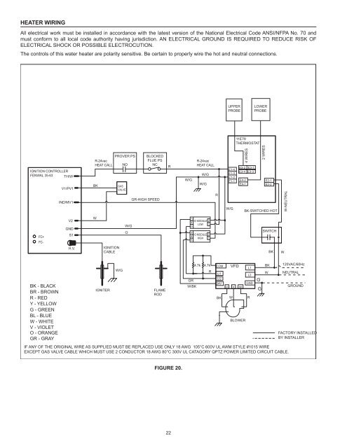
Heater WiringAll electrical work must be installed in accordance with the latest version of the National Electrical Code ANSI/NFPA No. 70 andmust conform to all local code authority having jurisdiction. AN ELECTRICAL GROUND IS REQUIRED TO REDUCE RISK OFELECTRICAL SHOCK OR POSSIBLE ELECTROCUTION.The controls of this water heater are polarity sensitive. Be certain to properly wire the hot and neutral connections.UPPERPROBELOWERPROBE11E79THERMOSTATIGNITION CONTROLLERFENWAL 35-63 TH/WV1/PV1IND/MV1R-24vacHEAT CALLBKPROVER PSNOGASVALVEBLOCKEDFLUE PSNCGR-HIGH SPEEDRW/GR-24vacHEAT CALLW/GW/GRW/G4 WIRES2 WIRESE3-2 E3-1E1-4E3-4 E3-3E1-3E1-2E1-1 E4-2E4-1E2-1E2-2BK-SWITCHED HOTW-NEUTRALFC+FC-V2GNDS1H.V.WIGNITIONCABLEW/GO345345IO MODULELOWIO MODULEHIGH2121SWITCHBKWBK - BLACKBR - BROWNR - REDY - YELLOWG - GREENBL - BLUEW - WHITEV - VIOLETO - ORANGEGR - GRAYIGNITERW/GFLAMERODIF ANY OF THE ORIGINAL WIRE AS SUPPLIED MUST BE REPLACED USE ONLY 18 AWG 105°C 600V UL AWM STYLE #1015 WIREEXCEPT GAS VALVE CABLE WHICH MUST USE 2 CONDUCTOR 18 AWG 80°C 300V UL CATAGORY QPTZ POWER LIMITED CIRCUIT CABLE.GRW/BK4.7k 4.7kRCOMLI1LI224VBKVFDU V WWBLOWERL1L2GNDRGGBKW120VAC/60HzNEUTRALGROUNDFACTORY INSTALLEDBY INSTALLERFigure 20.22
<strong>Gas</strong> PipingContact your local gas service company to ensure that adequategas service is available and to review applicable installation codesfor your area.Size the main gas line in accordance with Table 8. The figures shownare for straight lengths of pipe at 0.5 in. W.C. pressure drop, which isconsidered normal for low pressure systems. Note: Fittings such aselbows, tees and line regulators will add to the pipe pressure drop.Also refer to the latest version of the National Fuel <strong>Gas</strong> Code.Schedule 40 Steel or Wrought Iron Pipe is the preferred materialfor the gas line of this water heater. It is imperative to follow thesizing recommendations in the latest version of the National Fuel<strong>Gas</strong> Code if Corrugated Stainless Steel Tubing (CSST) is used asthe gas line for this water heater.The heater is not intended for operation at higher than 14.0" W.C.-natural gas, (1/2 pound per square inch gage) supply gas pressure.Exposure to higher supply pressure may cause damage to thegas valve which could result in fire or explosion. If overpressurehas occurred such as through improper testing of gas lines oremergency malfunction of the supply system, the gas valve must bechecked for safe operation. Make sure that the outside vents on thesupply regulators and the safety vent valves are protected againstblockage. These are parts of the gas supply system, not the heater.Vent blockage may occur during ice storms.Table 8 - GAS SUPPLY PIPE LENGTHS (IN FEET)Maximum Equivalent Pipe Length - Natural <strong>Gas</strong> OnlyInput rateSchedule 40 Steel or Wrought Iron Pipe(BTU/HR) 1/2" 3/4" 1" 1 1/4" 1 1/2"120,000 20 70 200 200 200154,000 10 40 150 200 200180,000 - 30 100 200 200199,000 - 30 90 200 200250,000 - 20 60 200 200275,000 - 10 50 200 200310,000 - 10 40 150 200366,000 - - 30 100 200390,000 - - 20 100 200Fitting Type*Equivalent length in feet45°Ell 0.7 1.0 1.2 1.6 1.990°Ell 1.6 2.1 2.6 3.5 4.0Tee 3.1 4.1 5.2 6.9 8.0Natural <strong>Gas</strong> 0.60 Specific Gravity, 0.50" W.C. Pressure Drop*Screwed FittingsIt is important to guard against gas valve fouling from contaminantsin the gas ways. Such fouling may cause improper operation, fireor explosion.If copper supply lines are used they must be internally tinned andcertified for gas service. Before attaching the gas line, be sure thatall gas pipe is clean on the inside.To trap any dirt or foreign material in the gas supply line, asediment trap must be incorporated in the piping (see Figure 21).The sediment trap must be readily accessible and not subject tofreezing conditions. Install in accordance with recommendations ofserving gas suppliers. Refer to the latest version of the NationalFuel <strong>Gas</strong> Code.To prevent damage, care must be taken not to apply too muchtorque when attaching gas supply pipe to gas valve inlet.Apply joint compounds (pipe dope) sparingly and only to themale threads of pipe joints. Do not apply compounds to the firsttwo threads. Use compounds resistant to the action of liquefiedpetroleum gases.<strong>Gas</strong> Meter Size – Natural <strong>Gas</strong>es OnlyBe sure the gas meter has sufficient capacity to supply the full ratedgas input of the water heater as well as the requirements of all othergas fired equipment supplied by the meter. If gas meter is too small, askthe gas company to install a larger meter having adequate capacity.GAS PIPING AND SEDIMENT TRAP INSTALLATION<strong>Gas</strong> Line Leak TestingFigure 21.Fire and Explosion HazardUse joint compound or Teflon tapecompatible with propane gas.Leak test before placing the waterheater in operation.Disconnect gas piping and main gasshutoff valve before leak testing.Install sediment trap in accordancewith NFPA 54.Any time work is done on the gas supply system perform a leak testto avoid the possibility of fire or explosion.1. For test pressures exceeding 1/2 psi (3.45 kPa) disconnect thewater heater and its Main <strong>Gas</strong> Shutoff Valve from the gas supplypiping system during testing, see Figure 21. The gas supply linemust be capped when disconnected from the water heater.2. For test pressures of 1/2 psi (3.45 kpa) or less, the water heaterneed not be disconnected, but must be isolated from the supplygas line by closing the Main <strong>Gas</strong> Shutoff Valve during testing.3. Coat all supply gas line joints and connections upstream of thewater heater with a non-corrosive soap and water solution totest for leaks. Bubbles indicate a gas leak. Do not use matches,candles, flame or other sources of ignition for this purpose.4. Repair any leaks before placing the water heater in operation.Purging<strong>Gas</strong> line purging is required with new piping or systems in which airhas entered.Purging should be performed per the current edition of NFPA 54 theNational Fuel <strong>Gas</strong> Code.23