Commercial Gas BCL275-400 (Series 104) - American Water Heaters
Commercial Gas BCL275-400 (Series 104) - American Water Heaters
Commercial Gas BCL275-400 (Series 104) - American Water Heaters

Create successful ePaper yourself
Turn your PDF publications into a flip-book with our unique Google optimized e-Paper software.
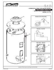
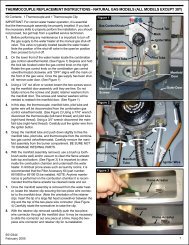
Supply gas pressure shall be measured while the water heateris not firing (static pressure) and while the water heater is firingat full capacity (dynamic pressure).If the supply gas pressure to the water heater is not betweenthe required minimum and maximum values given in Table 3on page 8 adjust the supply gas regulator as necessary. Adjustthe supply gas regulator(s) per the regulator manufacturer’sinstructions to achieve the required “static” and “dynamic”supply gas pressure.Multiple Appliance Installations:In multiple water heater installations or in installations wherethe installed water heater(s) share a common gas supply mainwith other gas fired appliances; the supply gas pressures shallbe measured at each water heater with all gas fired appliancesconnected to a common main firing at full capacity.On multiple water heater installations the supply gas line regulatorsshall be adjusted to provide gas pressure to each water heaterwithin the minimum and maximum supply pressure requirementslisted in Table 3 on page 8 with all gas fired appliances connectedto a common gas main firing at full capacity.Note: A pressure drop of more than 1.5” W. C. (0.37 kPa)when the Main Burner ignites is an indication of an inadequatesupply of gas and can lead to ignition failure, rough starts and/or rough operation. If a drop of more than 1.5” W. C. (0.37 kPa)in supply gas pressure occurs when the Main Burner ignites,ensure the supply gas lines and regulator(s) are properly sizedand installed. See the requirements for Supply <strong>Gas</strong> Regulatoron page 12 and <strong>Gas</strong> Piping on page 23. Ensure all requirementsand installation instructions are maintained.Checking VentingThe following steps shall be followed with each applianceconnected to the venting system placed in operation, while anyother appliances connected to the venting system are not inoperation.1. Seal any unused openings in the venting system.2. Inspect the venting system for proper size and horizontal pitch, asrequired in the National Fuel <strong>Gas</strong> Code, ANSI Z223.1or the CAN/CGA B149 Installation Codes and these instructions. Determinethat there is no blockage or restriction, leakage, corrosion andother deficiencies which could cause an unsafe condition.3. So far as is practical, close all building doors and windowsand all doors between the space in which the water heater(s)connected to the venting system are located and other spacesof the building. Turn on all appliances not connected to theventing system. Turn on all exhaust fans, such as range hoodsand bathroom exhausts, so they shall operate at maximumspeed. Close fireplace dampers.4. Follow the lighting instruction. Place the water heater beinginspected in operation. Adjust thermostat so the water heatershall operate continuously.5. Inspect vent system for leakage after 5 minutes of main burneroperation.6. After it has been determined that each appliance connectedto the venting system properly vents when tested as outlinedabove, return doors, windows, exhaust fans, fireplacedampers and any other gas burning appliance to their previousconditions of use.7. If improper venting is observed during any of the above tests,the venting system must be corrected.FAILURE TO CORRECT BACK DRAFTS MAY CAUSE AIRCONTAMINATION AND UNSAFE CONDITIONS.• If the back draft cannot be corrected by the normal method orif a suitable draft cannot be obtained, a blower type flue gasexhauster must be employed to assure proper venting andcorrect combustion.Checking the InputFollow these instructions to determine the firing rate of the waterheater.1. Follow the procedure described in the "Initial Start Up" sectionon page 24 to measure the static and dynamic supply gaspressures. Verify that the static and dynamic supply gaspressures conform to the values listed in Table 3 on page 8.2. Use this formula to “clock” the meter. Be sure that other gasconsuming appliances are not operating during this interval.(3600/T) x H = BtuhT = Time in seconds to burn one cubic foot of gas.H = Btu’s per cubic foot of gas.Btuh = Actual heater input.Example:T = 13.1 secondsH = 1000 BTU/Cu.Ft.Btuh = (3,600/13.1) x 1,000 = 275,000UNDER NO CIRCUMSTANCES SHOULD THE GAS INPUT EXCEEDTHE INPUT SHOWN ON THE HEATER'S RATING PLATE.<strong>Water</strong> Temperature Adjustment<strong>Water</strong> temperature over 125°F (52°C)can cause severe burns instantlyresulting in severe injury or death.Children, the elderly and thephysically or mentally disabled are athighest risk for scald injury.Feel water before bathing orshowering.Temperature limiting devices such asmixing valves must be installedwhen required by codes and toensure safe temperatures at fixtures.The water temperature is controlled by a thermostat, Fig. 3,which has two sensing elements. One sensor is located near thetop of the tank and the other is near the center. The thermostatis set in the lowest position before the heater leaves the factory.The thermostat temperature dial, Fig. 3, is accessible byremoving the control box cover. The dial is adjustable and maybe set for 120°F (49°C) to 180°F (82°C) water temperature, but120°F (49°C) is the recommended starting point. It is suggestedthe dial be placed on the lowest setting which produces anacceptable hot water supply. This will always give the mostenergy efficient operation. The temperature control has a 4°Ffixed differential.25