Standard Products Catalog - Omni Metalcraft Corp.
Standard Products Catalog - Omni Metalcraft Corp.
Standard Products Catalog - Omni Metalcraft Corp.

Create successful ePaper yourself
Turn your PDF publications into a flip-book with our unique Google optimized e-Paper software.
TABLE OF CONTENTSPages 2-7BELT CONVEYOR• Straights, curves and inclines• 1" belt width increments• Lengths in 1' incrementsPages 8-15BELT DRIVEN LIVE ROLLER CONVEYOR• Straights, curves and spurs• 1” between frame increments• Lengths in 1’ incrementsPages 16-21LINESHAFT CONVEYOR• Straights, curves and spurs• 1” between frame increments• Lengths in 1’ incrementsPages 22-23FLAT MOTOR DRIVEN ROLLER CONVEYOR• Straights and curves• 1” between frame increments• Length increments based on roller centers fortransportation and zones for zero pressurePages 24-25MOTOR DRIVEN ROLLER CONVEYOR• Straights and curves• Any between frame increments• Lengths in 1” incrementPages 26-29CHAIN DRIVEN LIVE ROLLER CONVEYOR• Straights and curves• Any effective width increments• Lengths in any incrementPage 30SCISSOR LIFTS• 2000 lbs., 4000 lbs. and 6000 lbs. capacity• Multiple platform sizes• Multiple raised and lowered heightsPages 31-41GRAVITY CONVEYOR• Ball transfer, flowrail, roller and skatewheel• Straights, curves and spurs• 1" between frame increments• Lengths in 1" incrementsBack CoverOPTIONS• Paint options and controls*Multiple curve radii available for all conveyors*Quote sheets online
DRIVE SPECIFICATIONSLEFT HAND CURVERIGHT HAND CURVE208-230/460VAC - 3 Phase - 60 Hz• Totally enclosed fan cooled• 1750 RPM• Inverter capable 4:1 speed ratio• 1.00 service factor• Sealed worm gear "C" face speed reducer115/230VAC - 1 Phase - 60 hz• Totally enclosed fan cooled• 1750 RPM• 1.15 service factor• Sealed worm gear "C" face speed reducerBELT SPECIFICATIONSTrackmate 120 EMB TM120RT-B TMIPH533EMBNominal Thickness 0.1 in 2.54 mm .225 in 5.7 mm .15 in 3.8 mmWeight .744 lbs. 3.6 kg/m 2 0.88 lbs. 4.3 kg/m 2 .96 lbs/ft 2 4.7 kg/m 2Temperature Minimum -10° F -23° C -10° F -23° C -10° F -23° CTemperature Maximum 180° F 82°C 158° F 70° C 176° F 80° CAdmissible Tensile Force 137 lbs./in 24 N/mm 61 lbs./in 11 N/mm 51 lbs./in 9 N/mmConveying SurfacePolyester fabric with PVCembossed coverPVC rough topPVC embossed cover; GripstructureApplicationsHorizontal package handling,transport conveying, diverseuses in material handlingand general conveyanceapplicationsDecline belt; Incline belt;Induction belt; Metering beltAcceleration belt; Baggagehandling - public view;Check-in belt; Induction belt;Metering/singulation beltPage 5
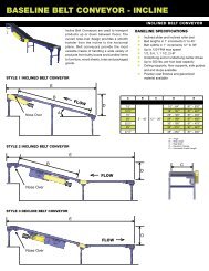
DRIVE SPECIFICATIONS208-230/460 VAC - 3 Phase - 60 Hz• Totally enclosed fan cooled• 1750 RPM• Inverter capable 4:1 speed ratio• 1.00 service factor115/230 VAC - 1 Phase - 60 hz• Totally enclosed fan cooled• 1750 RPM• 1.15 service factor• Sealed worm gear “C” face speed reducerLeft end Center right endCONVEYOR Capacity informationSLider BED Total LIVE LOAD CAPACITIES25° Incline HP30 FPM 60 FPM 90 FPMBelt Width Belt Width Belt Width12" 24" 36" 12" 24" 36" 12" 24" 36"BED LENGTH20401/2 420 400 375 195 175 150 120 95 753/4 650 625 600 310 285 260 195 175 1501 875 850 825 420 400 375 270 250 2251 1/2 1325 1300 1275 650 625 600 420 400 3752 1775 1750 1730 875 850 825 575 550 5251/2 405 360 315 175 135 90 100 60 153/4 630 585 540 290 245 205 175 135 901 855 810 765 405 360 315 250 210 1651 1/2 1305 1260 1220 630 585 540 405 360 3152 1755 1715 1670 855 810 765 555 510 465ROLLER BED total LIVE LOAD CAPACITIES25° Incline HP30 FPM 60 FPM 90 FPMBelt Width Belt Width Belt Width12" 24" 36" 12" 24" 36" 12" 24" 36"BED LENGTH20'40'1/2 630 590 555 295 255 220 180 145 1103/4 965 925 890 460 425 390 295 255 2201 1300 1260 1225 630 590 555 405 370 3351 1/2 1970 1930 1895 965 925 890 630 590 5552 2640 2600 2565 1300 1260 1225 850 815 7801/2 600 535 470 265 200 135 150 85 253/4 935 870 805 430 365 300 265 200 1351 1270 1205 1140 600 535 470 375 310 2451 1/2 1940 1875 1810 935 870 805 600 535 4702 2610 2545 2480 1270 1205 1140 820 755 695Page 7
BDLR - STRAIGHTBELT DRIVEN LIVE ROLLER CONVEYORBBelt Driven Live Roller (BDLR) Conveyor is aversatile way to convey products of variousshapes, sizes, and weights. <strong>Products</strong> such asboxes, cases, drums and totes are ideal for thisproduct line. Accumulating, diverting, mergingand transportation are all normal applicationsfor Belt Drive Live Roller Conveyors.Aspecifications• Transportation and minimum pressureaccumulation• Lengths in 1' increments 5' to 102'• Between frame in 1" increments 13" to 39"• Up to 120 FPM max speed• Ceiling supports, floor supports, side guidesand end stops available• Powder coat finishes and galvanizedmaterial available*Expanded product parameters availableCRef. 1.9"A 13" - 39"B 5' - 102'C 20.5" - 89"A = Between Frame (BF)B = Overall Length (OAL)C = Top of Roller (TOR)ROLLER SPECIFICATIONS AND CROSS SECTIONSROLLERDIAMETERBEARINGS TUBE DETAIL AXLE DETAILDetailswallThicknessROLLERSPACINGMAXLOAD PERROLLERGALVANIZED FRAMEMaterial Size Type Retention Centers lbs. 12 ga. Formed Channel1.9"Non-Precision orABEC Precision16 ga. Galvanized 7/16" Hex Spring 3" and 6" 260 6 1/2" deep x 1 1/2" flangeTransportationCost effective design for transporting productMinimum pressureAdditional adjustment for transporting product andaccumulating with minimum pressure betweenproductstread roller(Pop-OUT ROLler)pressure rollerreturn rollerTRANSPORTATIONMINIMUM PRESSUREThumb screw adjustment enables user to "fine-tune"pressure roller driving force and accumulate productwith minimum back pressure.Page 8
DRIVE SPECIFICATIONS208-230/460VAC - 3 Phase - 60 Hz• Totally enclosed fan cooled• 1750 RPM• Inverter capable 4:1 speed ratio• 1.00 service factor• Sealed worm gear "C" face speed reducer115/230VAC - 1 Phase - 60 hz• Totally enclosed fan cooled• 1750 RPM• 1.15 service factor• Sealed worm gear "C" face speed reducerFLOWFLOWFLOWEND - UNDERHUNG DRIVELEFT HAND DRIVERIGHT HAND DRIVEFLOWCENTER - UNDERHUNG DRIVEEND - underhungEnd drive locations are the most economicalchoice when products will only be conveyed in onedirection.Center - underhungCenter drive locations offer additional flexibilityby enabling the conveyor to reverse product flow.<strong>Products</strong> can conveyed in either direction withoutdamaging the belt.HORSEPOWER AND LOAD SPECIFICATIONSMAXIMUM UNIFORMLY DISTRIBUTED LIVE LOADBELT DRIVEN LIVE ROLLER CONVEYOR AT 60 FPMHP13" - 18" BETWEEN FRAME 19" - 26" BETWEEN FRAME 27" - 39" BETWEEN FRAME5' - 50' 55' - 100' 5' - 50' 55' - 100' 5' - 50' 55' - 100'1/2 650 N/A 270 N/A N/A N/A3/4 1510 510 1130 N/A 430 N/A1 2460 1460 2100 670 1400 N/A1 1/2 3760* 3100 3400* 2000 2780 750*2 5400* 4300* 5000* 3600* 4400* 2370**8 inch diameter drive pulley in lieu of 4 inch diameter drive pulleyPage 9
V-BDLR - CURVEV-BELT DRIVEN LIVE ROLLER CURVE CONVEYORV-Belt Driven Live Roller (BDLR) CurveConveyors are a versatile way to conveyproducts of various shapes, sizes, and weights.<strong>Products</strong> such as boxes, cases, drums, andtotes are conveyed easily on V-Belt BDLRCurves.Especifications• 30°, 45°, 60° and 90° turns• 36" inside radius• Between frame in 1" increments 13" to 39"• Up to 120 FPM max speed• 1/2, 3/4, 1, 1 1/2, 2 HP• Underhung end drives• Up to 500 lbs. total live load capacity• Ceiling supports, floor supports, side guidesand end stops available• Powder coat finishes and galvanizedmaterial available*Expanded product parameters availableARef. 1.9"A 13" - 39"B 49" - 75"C 22" - 90.5"D 36"E 12", 18"90°DBCA = Between Frame (BF)B = Outside Radius (OR)C = Top of Roller (TOR)D = Inside Radius (IR)E = Tangent LengthEAROLLER SPECIFICATIONSROLLER DIAMETER1.9"1.9" Tapered(2 1/2" - 1 11/16")BEARINGS TUBE DETAIL AXLE DETAILDetailsNon-Precision orABEC PrecisionwallThicknessROLLERSPACINGMAXLOAD PERROLLERGALVANIZED FRAMEMaterial Size Type Retention Centers lbs. 12 ga. Formed Channel16 ga. Galvanized 7/16" Hex Spring 3" Up to 120 6 1/2" deep x 1 1/2" flangeNon-Precision 16 ga. Galvanized 7/16" Hex Spring 3" Nominal Up to 120 6 1/2" deep x 1 1/2" flangenon-precision BEARING (NP)Non-Precision bearings are made of a stampedmetal housing with very loose tolerances. They arenot intended for very heavy loads or high speeds.precision Bearings (P)Precision Bearings are made from high quality steel, heattreated to uniform hardness and ground to a micro finish.The tolerances are much tighter than semi-precisionbearings making them capable of greater speeds andload capacities but sensitive to axle deflection causingmisalignment.DEGREE OFCURVEQUANTITY OF ROLLERS PERCURVETapered RollersPer CurveStraight RollersPer CurveTangentLength30° 8 12 18"45° 12 8 12"60° 16 8 12"90° 24 8 12"Page 10
CURVE SPECIFICATIONS45° CURVE 60° CURVENote: 45°, 60° and 90° curves are supplied with 12" tangents18"18"30° CURVEDRIVE SPECIFICATIONS208-230/460VAC - 3 Phase - 60 Hz• Totally enclosed fan cooled• 1750 RPM• Inverter capable 4:1 speed ratio• 1.00 service factor• Sealed worm gear "C" face speed reducer115/230VAC - 1 Phase - 60 hz• Totally enclosed fan cooled• 1750 RPM• 1.15 service factor• Sealed worm gear "C" face speed reducerPage 11
BDLR - STRAIGHT SPURBELT DRIVEN LIVE ROLLER STRAIGHT SPUR CONVEYORCBelt Driven Live Roller (BDLR) Straight SpurConveyors are a versatile way to conveyproducts off of a main line. They can conveyvarious shapes, sizes, and weights. <strong>Products</strong>such as boxes, cases, drums, and totes conveyeasily on BDLR Straight Spur Conveyors. Thislive roller spur can be self powered or slavedriven.ASpecifications• 30° and 45° spurs• Between frame in 1" increments 13" to 39"• Up to 600 FPM max speed• Up to 500 lbs. total live load capacity• Ceiling supports, floor supports and sideguides available• Powder coat finishes and galvanizedmaterial available*Expanded product parameters availableBRef. 1.9"A 13" - 39"B 22" - 90.5"C 33 1/8" - 53 1/4"D 54 1/8" - 105 1/2"E 30 7/8" - 62 1/4"F 28 3/4" - 40"DA = Between Frame (BF)B = Top of Roller (TOR)C = Short RailD = Long RailE = Trunk Line DisplacementF = Take Off DisplacementROLLER SPECIFICATIONS AND BEARING DETAILSROLLERDIAMETERBEARINGS TUBE DETAIL AXLE DETAILDetailswallThicknessROLLERSPACINGMAXLOAD PERROLLERGALVANIZED FRAMEMaterial Size Type Retention Centers lbs. 12 ga. Formed Channel1.9"Non-Precision orABEC Precision16 ga. Galvanized 7/16" Hex Spring 3" 260 6 1/2" deep x 1 1/2" flangenon-precision BEARING (NP)Non-Precision bearings are made of a stampedmetal housing with very loose tolerances. They arenot intended for very heavy loads or high speeds.precision Bearings (P)Precision Bearings are made from high quality steel,heat treated to uniform hardness and ground to amicro finish. The tolerances are much tighter thansemi-precision bearings making them capable ofgreater speeds and load capacities but sensitive toaxle deflection causing misalignment.Right HAndLeft HandPage 12
SPUR DETAILSETrunk Line BFF45°CDANote: Minimum recommended product length to converge or diverge product is 12"A = Between Frame (BF)B = Top of Roller (TOR)C = Short RailD = Long RailE = Trunk Line DisplacementF = Take Off DisplacementSPUR AND DRIVE SPECIFICATIONSBETWEENFRAMEWIDTH (A)30° SPUR CONVEYOR 45° SPUR CONVEYORC (In.) D (in.) E (in.) F (in.) C (In.) D (in.) E (in.) F (in.)13" 53 1/4 75 3/4 55 3/4 32 1/4 41 1/8 54 1/8 33 5/8 33 5/814" 51 1/2 75 3/4 55 31 3/4 40 1/8 54 1/8 33 3/8 33 3/815" 49 7/9 75 3/4 54 1/4 31 3/8 39 1/8 54 1/8 33 3316" 48 75 3/4 53 1/2 30 7/8 38 1/8 54 1/8 32 5/8 32 5/817" 46 1/3 75 3/4 52 3/4 30 1/2 37 1/8 54 1/8 32 1/4 32 1/418" 44 4/7 75 3/4 52 30 36 1/8 54 1/8 31 7/8 31 7/819" 42 5/6 75 3/4 51 1/4 29 5/8 35 1/8 54 1/8 31 1/2 31 1/220" 41 1/9 75 3/4 50 1/2 29 1/8 34 1/8 54 1/8 31 1/4 31 1/421" 39 3/8 75 3/4 49 3/4 28 3/4 33 1/8 54 1/8 30 7/8 30 7/822" 52 2/3 90 3/4 62 35 3/4 41 1/8 63 1/8 36 7/8 36 7/823" 51 90 3/4 61 1/4 35 3/8 40 1/8 63 1/8 36 1/2 36 1/224" 49 1/6 90 3/4 60 1/2 34 7/8 39 1/8 63 1/8 36 1/8 36 1/825" 47 4/9 90 3/4 59 3/4 34 1/2 38 1/8 63 1/8 35 3/4 35 3/426" 45 5/7 90 3/4 59 34 1/8 37 1/8 63 1/8 35 1/2 35 1/227" 44 90 3/4 58 1/4 33 5/8 36 1/8 63 1/8 35 1/8 35 1/828" 42 1/4 90 3/4 57 1/2 33 1/4 35 1/8 63 1/8 34 3/4 34 3/429" 40 1/2 90 3/4 56 3/4 32 3/4 34 1/8 63 1/8 34 3/8 34 3/830" 38 4/5 90 3/4 56 32 3/8 33 1/8 63 1/8 34 3431" 52 105 3/4 68 1/4 39 3/8 41 1/8 72 1/8 40 4032" 50 1/3 105 3/4 67 1/2 39 40 1/8 72 1/8 39 5/8 39 5/833" 48 3/5 105 3/4 66 3/4 38 1/2 39 1/8 72 1/8 39 3/8 39 3/834" 46 6/7 105 3/4 66 38 1/8 38 1/8 72 1/8 39 3935" 45 1/8 105 3/4 65 1/4 37 5/8 37 1/8 72 1/8 38 5/8 38 5/836" 43 2/5 105 3/4 64 1/2 37 1/4 36 1/8 72 1/8 38 1/8 38 1/837" 41 2/3 105 3/4 63 3/4 36 3/4 35 1/8 72 1/8 37 7/8 37 7/838" 40 105 3/4 63 36 3/8 34 1/8 72 1/8 37 5/8 37 5/839" 38 1/5 105 3/4 62 1/4 35 7/8 33 1/8 72 1/8 37 1/4 37 1/4208-230/460VAC - 3 Phase - 60 Hz• Totally enclosed fan cooled• 1750 RPM• Inverter capable 4:1 speed ratio• 1.00 service factor• Sealed worm gear "C" face speed reducer115/230VAC - 1 Phase - 60 hz• Totally enclosed fan cooled• 1750 RPM• 1.15 service factor• Sealed worm gear "C" face speed reducerPage 13
BDLR - CURVE SPURBELT DRIVEN LIVE ROLLER CURVE SPUR CONVEYORCBelt Driven Live Roller (BDLR) Curve SpurConveyors are a versatile way to conveyproducts off of a main line. They can conveyvarious shapes, sizes, and weights. <strong>Products</strong>such as boxes, cases, drums, and totes conveyeasily on BDLR Straight Spur Conveyors.DAspecifications• 30° and 45° spurs• Between frame in 1" increments 13" to 39"• Up to 600 FPM max speed• 1/2, 3/4, 1, 1 1/2, 2 HP• Up to 500 lbs. total live load capacity• Ceiling supports, floor supports, side guidesand end stop available• Powder coat finishes and galvanizedmaterial available*Expanded product parameters availableGBRef. 1.9"A 13" - 39"B 22" - 90 1/2"C 15 1/8" - 35 1/4"D 36 1/8" - 87 3/4"E 31 3/4" - 74 1/2"F 72" - 92"G 12", 24"A = Between Frame (BF)B = Top of Roller (TOR)C = Short RailD = Long RailE = Trunk Line DisplacementF = Take off DisplacementG = TangentROLLER SPACING AND BEARING DETAILSROLLERDIAMETERBEARINGS TUBE DETAIL AXLE DETAILDetailswallThicknessROLLERSPACINGMAXLOAD PERROLLERGALVANIZED FRAMEMaterial Size Type Retention Centers lbs. 12 ga. Formed Channel1.9"Non-Precision orABEC Precision16 ga. Galvanized 7/16" Hex Spring 3" and 6" 260 6 1/2" deep x 1 1/2" flangenon-precision BEARING (NP)Non-Precision bearings are made of a stampedmetal housing with very loose tolerances. They arenot intended for very heavy loads or high speeds.precision Bearings (P)Precision Bearings are made from high qualitysteel, heat treated to uniform hardness and groundto a micro finish. The tolerances are much tighterthan semi-precision bearings making them capableof greater speeds and load capacities but sensitiveto axle deflection causing misalignment.Right HAndLeft Hand208-230/460VAC - 3 Phase - 60 Hz• Totally enclosed fan cooled• 1750 RPM• Inverter capable 4:1 speed ratio• 1.00 service factor• Sealed worm gear "C" face speed reducer115/230VAC - 1 Phase - 60 hz• Totally enclosed fan cooled• 1750 RPM• 1.15 service factor• Sealed worm gear "C" face speed reducerPage 14
ASPUR DETAILSETrunk Line BFC45°DFGA = Between Frame (BF)B = Top of Roller (TOR)C = Short RailD = Long RailE = Trunk Line DisplacementF = Take off DisplacementG = TangentSPUR SPECIFICATIONSBETWEENFRAMEWIDTH(A)30° SPUR CONVEYOR WITH 60° CURVE 45° SPUR CONVEYOR WITH 45° CURVEC (in.) D (in.) E (in.) F (in.) G (in.) C (in.) D (in.) E (in.) F (in.) G (in.)13" 35 1/4 57 3/4 61 1/2 72 12 23 1/8 36 1/8 33 3/8 75 2414" 33 1/2 57 3/4 61 72 12 22 1/8 36 1/8 33 1/4 75 2415" 31 7/9 57 3/4 60 1/2 72 12 21 1/8 36 1/8 33 75 2416" 30 57 3/4 60 72 12 20 1/8 36 1/8 32 3/8 75 2417" 28 1/3 57 3/4 59 1/2 72 12 19 1/8 36 1/8 32 5/8 75 2418" 26 4/7 57 3/4 59 72 12 18 1/8 36 1/8 32 3/8 75 2419" 24 5/6 57 3/4 58 1/2 72 12 17 1/8 36 1/8 32 1/8 75 2420" 23 1/9 57 3/4 58 72 12 16 1/8 36 1/8 32 75 2421" 21 3/8 57 3/4 57 1/2 72 12 15 1/8 36 1/8 31 3/4 75 2422" 34 2/3 72 3/4 70 79 1/2 12 26 1/8 48 1/8 40 83 1/2 2423" 33 72 3/4 69 1/2 79 1/2 12 25 1/8 48 1/8 39 3/4 83 1/2 2424" 31 1/6 72 3/4 69 79 1/2 12 24 1/8 48 1/8 39 5/8 83 1/2 2425" 29 4/9 72 3/4 68 1/2 79 1/2 12 23 1/8 48 1/8 39 3/8 83 1/2 2426" 27 5/7 72 3/4 68 79 1/2 12 22 1/8 48 1/8 39 1/4 83 1/2 2427" 26 72 3/4 67 1/2 79 1/2 12 21 1/8 48 1/8 39 83 1/2 2428" 24 1/4 72 3/4 67 79 1/2 12 20 1/8 48 1/8 38 3/4 83 1/2 2429" 22 1/2 72 3/4 66 1/2 79 1/2 12 19 1/8 48 1/8 38 5/8 83 1/2 2430" 20 4/5 72 3/4 66 79 1/2 12 18 1/8 48 1/8 38 3/8 83 1/2 2431" 34 87 3/4 78 1/2 87 12 29 1/8 60 1/8 46 5/8 92 2432" 32 1/3 87 3/4 78 87 12 28 1/8 60 1/8 46 3/8 92 2433" 30 3/5 87 3/4 77 1/2 87 12 27 1/8 60 1/8 46 1/4 92 2434" 28 6/7 87 3/4 77 87 12 26 1/8 60 1/8 46 92 2435" 27 1/8 87 3/4 76 1/2 87 12 25 1/8 60 1/8 45 3/8 92 2436" 25 2/5 87 3/4 76 87 12 24 1/8 60 1/8 45 5/8 92 2437" 23 2/3 87 3/4 75 1/2 87 12 23 1/8 60 1/8 45 3/8 92 2438" 22 87 3/4 75 87 12 22 1/8 60 1/8 45 1/4 92 2439" 20 1/5 87 3/4 74 1/2 87 12 21 1/8 60 1/8 45 92 24Page 15
LINESHAFT - STRAIGHTLINESHAFT DRIVEN ROLLER CONVEYORBLineshaft Conveyors are an optimum solutionfor economical conveyance of light loads.They are designed for flat-bottomed, evenlydistributed loads such as those found indistribution and warehousing, food packagingand parcel handling. Clean, dry, oil freeenvironments are the ideal conditions tomaximize performance.specificationsA• Lengths in 1' increments 3' to 100'• Between frame in 1" increments 10" to 39"• 25 to 120 FPM max speed• Up to 75 lbs. per product load capacity• Minimum pressure• Ceiling supports, floor supports, sideguides and end stops available• Powder coat finishes and galvanizedmaterial available*Expanded product parameters availableCRef. 1.4" 1.9"A 10" - 28" 13" - 39"B 3' - 100'C 22" - 88"A = Between Frame (BF)B = Overall Length (OAL)C = Top of Roller (TOR)ROLLER SPACING AND BEARING DETAILSROLLERDIAMETERBEARINGS TUBE DETAIL AXLE DETAIL ROLLER SPACINGDetailswallThicknessMAX LOADPER ROLLERGALVANIZED FRAMEMaterial Size Type Retention Centers lbs. 12 ga. Formed Channels1.4" Non-Precision 16 ga. Galvanized 5/16" Hex Spring 1.5" and 3" 10 5 1/2" deep x 1 1/2" flange1.9"Non-Precision orABEC Precision16 ga. Galvanized 7/16" Hex Spring 2", 3", 4", 6" and 8" 15 5 1/2" deep x 1 1/2" flangenon-precision BEARING (NP)Non-Precision bearings are made of a stampedmetal housing with very loose tolerances. They arenot intended for very heavy loads or high speeds.FLOWprecision Bearings (P)Precision bearings are made from high quality steel,heat treated to uniform hardness and ground to amicro finish. The tolerances are much tighter thansemi-precision bearings making them capable ofgreater speeds and load capacities but sensitive toaxle deflection causing misalignment.RollerDrive BeltDrive SpoolRetaining ClipDrive ShaftPage 16
DRIVE SPECIFICATIONS208-230/460VAC - 3 Phase - 60 Hz• 190/380vac - 3 Phase - 50 Hz capable• Totally enclosed fan cooled• 1750 RPM• Inverter capable 4:1 speed ratio• 1.00 service factor• Sealed worm gear "C" face speed reducerDRIVE MOUNTING OPTIONS AVAILABLEUNDERHUNG DRIVE115/230VAC - 1 Phase - 60 hz• Totally enclosed fan cooled• 1750 RPM• 1.15 service factor• Sealed worm gear "C" face speed reducerSIDE MOUNTED DRIVECONVEYOR SPECIFICATIONSROLLERCENTERSMAXIMUM LENGTH (FEET) PER 1/4 HPFPM30 45 60 75 90 105 120MAXIMUM LENGTH PER DRIVE SECTION(FEET)ROLLERCENTERSDRIVESECTION ATENDDRIVESECTION ATCENTER1.5" 20 15 10 8.5 6.5 6 52" 26 20 13 11 8.5 7.5 6.53" 40 30 20 16.5 13 11.5 104" 50 37.5 25 21 17 15 136" 80 60 40 32.5 25 22.5 208" 100 75 50 41.5 33 29 251.5" 35 702" 45 903" 60 1204" 90 1806" 150 3008" 180 380STANDARD SPECIFICATIONSDRIVE SHAFT• 1 in. dia. steel shaft full length of conveyor• Delrin chain coupling at bed jointsDrive spools• 2 in. dia. Delrin spool held in place on shaft by "snap on" retaining clipsDrive belts• 3/16 in. dia. urethane belts from drive spools to rollersspeed reduction• "C" face speed reducer.• No. 50 chain from reducer to drive shaftPage 17
LINESHAFT - CURVELINESHAFT DRIVEN ROLLER CURVE CONVEYORLineshaft Curve Conveyors are an optimumsolution for economic conveyance of lightloads. They are designed for flat-bottomed,evenly distributed loads such as thosefound in distribution and warehousing, foodpackaging and parcel handling. Clean, dry, oilfree environments are the ideal conditions tomaximize performance.specifications• 30°, 45°, 60° and 90° turns• 36" inside radius• Between frame in 1" increments 10" to 39"• Up to 120 FPM max speed• Ceiling supports, floor supports, side guidesand end stops available• Powder coat finishes and galvanizedmaterial available*Expanded product parameters availableAB90°CRef. 1.4" 1.9"A 10" - 28" 13" - 39"B 46" - 64" 49" - 75"C 22" - 88"D 36"A = Between Frame (BF)B = Outside Radius (OR)C = Top of Roller (TOR)D = Inside Radius (IR)ADAccumulation not recommended on Lineshaft Curves.ROLLER SPECIFICATIONSCURVE TYPEINSIDERADIUSROLLERDIAMETERBEARINGS TUBE DETAIL AXLE DETAILDetailswallThicknessROLLERSPACINGMAXLOAD PERROLLERMaterial Size Type Retention Centers lbs.30°, 45°, 60°, 90°36" 1.4" Tapered Non-Precision 16 ga. Galvanized 5/16" Hex Spring36" 1.9" Tapered Non-Precision 16 ga. Galvanized 7/16" Hex Spring1.5"Nominal3"Nominal1015non-precision BEARING (NP)Non-Precision bearings are made of astamped metal housing with very loosetolerances. They are not intended forvery heavy loads or high speeds.ROLLER QUANTITY BY CURVE SIZEROLLER DIAMETER(TAPERED)1.4( 1 1/2" to 1")1.9(2 1/2" to 1 11/16")30° 45° 60° 90°Tapered Straight Tapered Straight Tapered Straight Tapered Straight10 16 16 0 20 0 32 08 8 12 0 16 0 24 0Page 18
CURVE SPECIFICATIONS1 3/8" Diameter x 16 Ga. Roller curveBETWEENFRAMEWIDTHCONVEYOR WEIGHT (lbs.)30° 45° 60° 90°10" 51 93 109 17411" 59 94 112 17812" 67 96 114 18213" 75 97 117 18714" 82 98 119 19115" 90 99 122 19516" 98 101 124 19917" 106 102 127 20318" 114 103 129 20719" 122 105 132 21220" 129 106 134 21621" 137 107 137 22022" 145 108 139 22423" 153 110 142 22824" 161 111 144 23225" 169 112 147 23726" 176 113 149 24127" 184 115 152 24528" 192 116 154 24912"30°12"30° CurveNote: 30° curves are supplied with 12" tangents1.9" Diameter x 16 Ga. Roller curveBETWEENFRAMEWIDTHCONVEYOR WEIGHT (lbs.)30° 45° 60° 90°13" 126 89 121 19414" 129 91 124 19915" 132 94 128 20316" 135 96 131 20817" 138 98 134 21318" 140 101 137 21719" 143 103 141 22220" 146 105 144 22721" 149 108 147 23122" 152 110 150 23623" 155 112 154 24124" 158 115 157 24525" 161 117 160 25026" 164 120 164 25527" 166 122 167 25928" 169 124 170 26429" 172 127 173 26830" 175 129 177 27331" 178 131 180 27832" 181 134 183 28233" 184 136 186 28734" 187 138 190 29235" 189 141 193 29636" 192 143 196 30137" 195 145 199 30638" 198 148 203 31039" 201 150 206 31545° Curve60° CurvePage 19
LINESHAFT - SPURLINESHAFT DRIVEN ROLLER SPUR CONVEYORLineshaft Spur Conveyors are an optimumsolution for economic conveyance of lightloads and are a versatile way to conveyproducts to and from a main line. They aredesigned for flat-bottomed, evenly distributedloads such as those found in distribution andwarehousing, food packaging and parcelhandling. Clean, dry, oil free environments arethe ideal conditions to maximize performance.specifications• 30° and 45° spurs• Between frame in 1" increments 10" to 39"• Up to 120 FPM max speed• Up to 75 lbs. per product load capacity• Ceiling supports, floor supports, sideguides and end stops available• Powder coat finishes and galvanizedmaterial available*Expanded product parameters availableACERef. 1.4" 1.9"A 10" - 28" 13" - 39"B 22" - 88"C 12" - 21"D 36" - 84"E 23 7/8" - 84 1/2"BA = Between Frame (BF)B = Top of Roller (TOR)C = Short Rail LengthD = Long Rail LengthE = Shelf Bracket LengthDROLLER SPACING AND BEARING DETAILSROLLER SPACING AND BEARING DETAILSROLLERDIAMETERBEARINGS TUBE DETAIL AXLE DETAIL ROLLER SPACINGDetailswallThicknessMAX LOADPER ROLLERGALVANIZED FRAMEMaterial Size Type Retention Centers lbs. 12 ga. Formed Channels1.4" Non-Precision 16 ga. Galvanized 5/16" Hex Spring 1.5" and 3" 10 5 1/2" deep x 1 1/2" flange1.9"Non-Precision orABEC Precision16 ga. Galvanized 7/16" Hex Spring 2", 3", 4", 6" and 8" 15 5 1/2" deep x 1 1/2" flangenon-precision BEARING (NP)Non-Precision bearings are made of a stampedmetal housing with very loose tolerances. They arenot intended for very heavy loads or high speeds.precision Bearings (P)Precision bearings are made from high quality steel,heat treated to uniform hardness and ground to amicro finish. The tolerances are much tighter thansemi-precision bearings making them capable ofgreater speeds and load capacities but sensitive toaxle deflection causing misalignment.Right HAndLeft HandPage 20
SPUR DETAILS45°CDBETWEENFRAMEWIDTH (A)30° SPUR CONVEYOR 45° SPUR CONVEYORE (in.) D (in.) C (in.) E (in.) D (in.) C (in.)10" 30 13/16 36 15 23 7/8 36 2411" 30 13/16 36 15 23 7/8 36 2412" 30 13/16 36 12 23 7/8 36 2413" 30 13/16 36 12 28 1/8 36 2114" 37 3/4 48 21 28 1/8 36 2115" 37 3/4 48 21 28 1/8 36 2116" 37 3/4 48 18 32 3/8 36 1817" 44 11/16 48 15 32 3/8 36 1818" 44 11/16 48 15 32 3/8 36 1819" 44 11/16 48 12 36 9/16 36 1520" 44 11/16 48 12 36 9/16 36 1521" 53 1/2 60 21 36 9/16 36 1522" 53 1/2 60 18 40 13/16 36 1223" 53 1/2 60 18 40 13/16 36 1224" 58 9/16 60 15 40 13/16 36 1225" 58 9/16 60 15 45 1/16 48 2126" 58 9/16 60 12 45 1/16 48 2127" 58 9/16 60 12 45 1/16 48 2128" 67 3/16 72 21 49 5/16 48 1829" 67 3/16 72 18 49 5/16 48 1830" 67 3/16 72 18 49 5/16 48 1831" 72 3/8 72 15 53 9/16 48 1532" 72 3/8 72 15 53 9/16 48 1533" 72 3/8 72 12 53 9/16 48 1534" 72 3/8 72 12 57 7/8 48 1235" 81 1/16 84 21 57 7/8 48 1236" 81 1/16 84 18 57 7/8 48 1237" 81 1/16 84 18 62 1/16 60 2138" 84 1/2 84 15 62 1/16 60 2139" 84 1/2 84 15 62 1/16 60 211.4 LS WIDTHS1.9 LS WIDTHSPage 21
FMDR - STRAIGHT AND CURVEFLAT MOTOR DRIVEN ROLLER CONVEYOR - STRAIGHTB24V Flat Motor Driven Roller Conveyor(FMDR) is an excellent conveyor choice whenenergy efficiency, ease of installation, lowmaintenance and minimal spare parts areprimary considerations. It is designed to workwell for both zero pressure accumulation andtransportation.ASpecifications• Length 1.5’ to 100’ maximum, incrementsbased on roller centers for transportationand zones for zero pressure• Between frame in 1” increments 13” to 39”• 30 to 120 FPM• Ceiling supports, floor supports and sideguides available• Powder coat finishes and galvanizedmaterial available*Expanded product parameters availableCRef. 1.9"A 13" - 39"B 1.5' - 100'C 13.25" - 89.5"A = Between Frame (BF)B = Overall Length (OAL)C = Top of Roller (TOR)FLAT MOTOR DRIVEN ROLLER CONVEYOR - CURVEspecifications• 30°, 45°, 60° and 90° turns• 36" standard inside radius• Between frame in 1” increments 13” to 39”• 30 to 120 FPM• Ceiling supports, floor supports and sideguides available• Powder coat finishes and galvanizedmaterial available*Expanded product parameters availableA90°BCRef. 1.9”A 13” - 39”B 49” - 75”C 13.25” - 89.5”D 36"A = Between Frame (BF)B = Outside Radius (OR)C = Top of Roller (TOR)D = Inside Radius (IR)Page 22AD
power supply• 24 VDC fixed output• NEMA 12 enclosure• 20 amp DC power supply• 115 VAC, 1 Phase, 60 Hz., 5.7 amp input• 230 VAC, 1 Phase, 60 Hz., 2.8 amp input• 460 VAC, 3 Phase, 60 Hz., 1.6 amp input• 5 amp DC power supply• 115 VAC, 1 Phase, 60 Hz., 1.4 amp input• 230 VAC, 1 Phase, 60 Hz., 0.8 amp input• 460 VAC, 3 Phase, 60 Hz., 0.5 amp inputMotorFMDR STRAIGHT DRIVESPECIFICATIONS• 24 VDC brushless motor, 75 watt• 14 in-lbs rated torqueSlave Rollers• 1.9" dia. x 16 ga. galvanized rollers• ABEC-1 precision bearingsroller spacing• 2", 3" and 4" roller centerspower supply• Optional 5 amp DC power supply• 115 VAC, 1 Phase, 60 Hz., 1.4 amp input• 230 VAC, 1 Phase, 60 Hz., 0.8 amp input• 460 VAC, 3 Phase, 60 Hz., 0.5 amp inputMOTORFMDR CURVE DRIVESPECIFICATIONS• 24 VDC brushless motor, 75 watt• 14 in-lbs rated torqueSlave Rollers• 2.5" dia. to 1-11/16" dia. zinc plated tapered rollers• ABEC-1 precision bearingsroller spacing• 3" roller centers, nominal roller spacingCurve ZONE QUANTITY• 60° and 90° - 2 zones• 30° and 45° - 1 zoneZERO PRESSURE AND TRANSPORTATION SPECIFICATIONSZero Pressure• 18", 24", 30" or 36" long drive zones• 75 lbs. maximum product load• 1 flat motor and ZPA module per zone• Variable speed potentiometer on ZPA module• Multiple operating modes• Zero pressure accumulation• High throughput zero pressure accumulation• Train mode (slug release)• Retro-reflective photo eyeZERO PRESSURE ENDVIEWTRANSPORTATION SYSTEMS• 16 rollers/drive zone maximum• 28 lbs. per foot maximum product load• 1 flat motor and driver module per zone• Variable speed potentiometer on driver module• Multiple speed options with DIP switches• Transports product without accumulationTRANSPORTATION ENDVIEWPage 23
MDR - STRAIGHT AND CURVEMOTOR DRIVEN ROLLER CONVEYOR - STRAIGHTMotor Driven Roller (MDR) Conveyors arean excellent choice when fast and easyinstallation, low maintenance and minimalspare parts are a primary consideration. Thequiet operating conveyor is great for zeropressure accumulation and transportation.specifications• Lengths in 1" increments 2' to 100'• Between frame in any increment 15" to 39"• 30 to 120 FPM max speed• Ceiling supports, floor supports, side guidesand end stops available• Powder coat finishes and galvanizedmaterial available*Expanded product parameters availableBACRef. 1.9"A 15" - 39"B 2' - 100'C 21" - 87"A = Between Frame (BF)B = Overall Length (OAL)C = Top of Roller (TOR)MOTOR DRIVEN ROLLER CONVEYOR - CURVEspecifications• 30°, 45°, 60° and 90° turns• 36" standard inside radius• Between frame in any increment 15" to 39"• Ceiling supports, floor supports, side guidesand end stops available• Powder coat finishes and galvanizedmaterial available*Expanded product parameters availableA90°BCRef.A 15" - 39"B 51" - 75"C 11" - 87"D 36"A = Between Frame (BF)B = Outside Radius (OR)C = Top of Roller (TOR)D = Inside Radius (IR)Page 24AD
MDR STRAIGHT DRIVESPECIFICATIONSpower supply• 5, 10 and 20 amp DC power supply• 24 VDC fixed output• 380 – 480 VAC , 3 Phase, 50-60 Hz., 0.65 amp input• NEMA 12 enclosureMotorized Drive Roller• 1.9" diameter• 24 VDC brushless internal motor, 22 watt• 8 in-lbs rated torque• 20 in-lbs starting torqueSlave Rollers• 1.9" dia. x 16 ga. galvanized rollers• ABEC-1 precision bearingsroller spacing• 3" roller centersMDR CURVE DRIVESPECIFICATIONSpower supply• OptionalMOTORIZED Drive Roller• 1.9" diameter mounted below slave rollers• 24 VDC brushless internal motor, 22 watt• 8 in-lbs rated torque• 20 in-lbs starting torqueSlave Rollers• 2.5" dia. to 1-11/16" dia. zinc plated tapered rollers• ABEC-1 precision bearingsroller spacing• 3" roller centers, nominal roller spacingCurve ZONE QUANTITY• 60° and 90° - 2 zones• 30° and 45° - 1 zoneZERO PRESSURE AND TRANSPORTATION SPECIFICATIONSZero Pressure• 18", 24" or 30" long drive zones• 75 lbs. maximum product load• 1 motorized drive roller and ZPA module per zone• Variable speed potentiometer on ZPA module• Multiple operating modes• Zero pressure accumulation• High throughput zero pressure accumulation• Train mode (slug release)• Retro-reflective photo eyeZERO PRESSURE ENDVIEWTRANSPORTATION SYSTEMS• 30" long drive zones• 30 lbs. per foot maximum product load• 1 motorized drive roller and driver module per zone• Variable speed potentiometer on driver module• Transports product without accumulationTRANSPORTATION ENDVIEWPage 25
CDLR - STRAIGHTCHAIN DRIVEN LIVE ROLLER CONVEYORBChain Driven Live Roller (CDLR) Conveyorsare ideal for transporting loaded pallets, tires,drums or other heavy items. The weldedconstruction makes them rugged and durableenough to handle even the toughest conditions.The sprocketed rollers and roll to roll chainsystem provide positive driving power to theproduct.specifications• Lengths in any increment up to 50'• Effective width in any increment 12" to 96"• Up to 80 FPM max speed• Up to 6000 lbs. per product load capacity• Floor supports, side guides and end stopsavailable• Powder coat finish standard*Expanded product parameters availableACRef. 1.9" 2.5" - 2.6" 3.5"A 12" - 54" 12" - 64" 12" - 96"B 3' - 50'C 12" - 48"A = Effective WidthB = Overall Length (OAL)C = Top of Roller (TOR)ROLLER SPACING, CHAIN AND SPROCKET DETAILSLACING OPTIONSCHAIN MINIMUM ROLLER SPACINGSIZE1.9" 2.5" 2.6" 3.5"STANDARD LACING - CHAIN GUARD ONE SIDE40 3 1/2" 4" 4" N/A50 3 3/4" 4 3/8" 4 3/8" N/A60 4 1/8" 4 1/2" 4 1/2" 6"80 N/A N/A 5 1/2" 6 1/2"SPECIAL LACING - WIDER CHAIN GUARD ONE SIDE40 2 3/4" 3 1/2" N/A N/A50 3 1/8" 3 7/16" 3 3/4" N/A60 N/A 3 3/4" 3 3/4" 4 7/8"80 N/A N/A N/A 5"POWER BOTH SIDES - CHAIN GUARD BOTH SIDES40 2 1/4" 2 3/4" 2 3/4" N/A50 2 1/2" 2 13/16" 2 13/16" N/A60 2 3/4" 3" 3" 3 3/4"80 N/A N/A 3 1/4" 3 3/4"ROLLEr configurationsSTANDARD ROLLERS LOWSTANDARD ROLLERS HIGHROLLERDIAMETERSROCKETS ANDCHAINSSerieswallThicknessTUBE DETAILAXLE DETAILMAXLOADMaterial Size Type Retention* lbs.FRAMEStructuralChannel40 Series 0.145" Mild Steel or Galvanized 7/16" Hex Spring or Pin 1500 5 x 6.7#1.9" 50 Series 0.145" Mild Steel or Galvanized 7/16" Hex Spring or Pin 1500 5 x 6.7#60 Series 0.145" Mild Steel or Galvanized 7/16" Hex Spring or Pin 1500 6 x 8.2#40 Series 11 ga. Mild Steel or Galvanized 11/16" Hex Spring or Pin 2500 5 x 6.7#2.5" 50 Series 11 ga. Mild Steel or Galvanized 11/16" Hex Spring or Pin 2500 5 x 6.7#60 Series 11 ga. Mild Steel or Galvanized 11/16" Hex Spring or Pin 2500 6 x 8.2#40 Series 0.180" Mild Steel or Galvanized 11/16" Hex Spring or Pin 3500 5 x 6.7#2.6"50 Series 0.180" Mild Steel or Galvanized 11/16" Hex Spring or Pin 3500 5 x 6.7#60 Series 0.180" Mild Steel or Galvanized 11/16" Hex Spring or Pin 3500 6 x 8.2#80 Series 0.180" Mild Steel or Galvanized 11/16" Hex Spring or Pin 3500 6 x 8.2#3.5"60 Series 0.300" Mild Steel 1-1/16" Hex Pin 6000 7 x 9.8#80 Series 0.300" Mild Steel 1-1/16" Hex Pin 6000 8 x 11.5#*Dependent upon between frame dimensionPage 26
DRIVE SPECIFICATIONS208-230/460VAC - 3 Phase - 60 Hz• Totally enclosed fan cooled• 1750 RPM• Inverter capable 4:1 speed ratio• 1.00 service factor• Sealed worm gear “C” face speed reducer115/230VAC - 1 Phase - 60 hz• Totally enclosed fan cooled• 1750 RPM• 1.15 service factor• Sealed worm gear “C” face speed reducerDRIVE MOUNTING OPTIONS AVAILABLELeft end Center right endDRIVE MOUNTED LOWDRIVE MOUNTED HIGHDRIVE MOUNTED UNDERHUNGGENERAL HP GUidelinesROLLERPRODUCTWEIGHTUP TO 10' UP TO 20' UP TO 30' UP TO 40' UP TO 50'2 PRODUCTS 4 PRODUCTS 6 PRODUCTS 8 PRODUCTS 10 PRODUCTS30 FPM 45 FPM 60 FPM 30 FPM 45 FPM 60 FPM 30 FPM 45 FPM 60 FPM 30 FPM 45 FPM 60 FPM 30 FPM 45 FPM 60 FPM1.92.52.63.5500 1/2 1/2 1/2 1/2 1/2 1/2 1/2 1/2 3/4 1/2 3/4 1 3/4 1 1-1/21000 1/2 1/2 3/4 1/2 3/4 3/4 3/4 1 1-1/2 3/4 1-1/2 1-1/2 1 1-1/2 22000 1/2 3/4 3/4 3/4 1-1/2 1-1/2 1-1/2 2 N/A 1-1/22500 1/2 3/4 1 1 1-1/2 2 1-1/2 23000 3/4 1 1-1/2 1-1/2 2 N/A 23500 3/4 1 1-1/2 1-1/2 2- Multiple drives or conveyor sections may be needed to meet your4000 1 1-1/2 1-1/2 2application capacity/speed requirements6000 1-1/2 2- Other roller, speed and horsepower combinations are availableROLLER CAPACITY INFORMATIONThe Maximum Roller Capacity chart is designed to helpdetermine the size of the roller required for a given loadand length. Use only 2/3 of the rollers under the productwhen calculating the required roller capacity because theconveying surface of products may not always be flat.non-precision BEARING (NP)Non-Precision bearings are made of a stampedmetal housing with very loose tolerances. They arenot intended for very heavy loads or high speeds.precision Bearings (P)Precision Bearings are made from high quality steel, heattreated to uniform hardness and ground to a micro finish.The tolerances are much tighter than semi-precisionbearings making them capable of greater speeds andload capacities but sensitive to axle deflection causingmisalignment.Page 27
CDLR - CURVECHAIN DRIVEN LIVE ROLLER CURVE CONVEYORChain Driven Live Roller (CDLR) CurveConveyors are ideal for transporting loadedpallets, tires, drums or other heavy items. Thewelded construction makes them rugged anddurable enough to handle even the toughestconditions. The sprocketed rollers and roll toroll chain system provide positive driving powerto the product.specifications• 30°, 45°, 60° and 90° turns• 36" minimum inside radius• Effective width in any increment 12" to 64"• Up to 80 FPM max speed• Floor supports, side guides and end stopsavailable• Powder coat finish standard*Expanded product parameters availableA wide variety of roller center options areavailable based on your specific radius andeffective width. Roller centers are measuredat the centerline of the conveying surface.Ref. 1.9" 2.5" 2.6" 3.5"A 12" - 54" 12" - 64"B Up to 116"C 12" - 48"D36" MinimumA = Effective WidthB = Outside Radius (OR)C = Top of Roller (TOR)D = Inside Radius (IR)PW = Package WidthPL = Package LengthPLAA = minimum effective width that yourpackage requires to maintain 2" of clearanceas it navigates the curve.A min= ( D + PW )√2 + ( PL/2 ) 2 - (D-2)PWB2" clearanceminimumC90°ADROLLER CHAIN AND SPROCKET SPECIFICATIONSROLLERDIAMETERSROCKETS ANDCHAINSSerieswallThicknessTUBE DETAILAXLE DETAILMAXLOADMaterial Size Type Retention* lbs.FRAMEStructuralChannel40 Series 0.145" Mild Steel or Galvanized 7/16" Hex Spring or Pin 1500 5 x 6.7#1.9" 50 Series 0.145" Mild Steel or Galvanized 7/16" Hex Spring or Pin 1500 5 x 6.7#60 Series 0.145" Mild Steel or Galvanized 7/16" Hex Spring or Pin 1500 6 x 8.2#40 Series 11 ga. Mild Steel or Galvanized 11/16" Hex Spring or Pin 2500 5 x 6.7#2.5" 50 Series 11 ga. Mild Steel or Galvanized 11/16" Hex Spring or Pin 2500 5 x 6.7#60 Series 11 ga. Mild Steel or Galvanized 11/16" Hex Spring or Pin 2500 6 x 8.2#40 Series 0.180" Mild Steel or Galvanized 11/16" Hex Spring or Pin 3500 5 x 6.7#2.6"50 Series 0.180" Mild Steel or Galvanized 11/16" Hex Spring or Pin 3500 5 x 6.7#60 Series 0.180" Mild Steel or Galvanized 11/16" Hex Spring or Pin 3500 6 x 8.2#80 Series 0.180" Mild Steel or Galvanized 11/16" Hex Spring or Pin 3500 6 x 8.2#3.5"60 Series 0.300" Mild Steel 1-1/16" Hex Pin 6000 7 x 9.8#80 Series 0.300" Mild Steel 1-1/16" Hex Pin 6000 8 x 11.5#*Dependent upon between frame dimensionPage 28
DRIVE SPECIFICATIONS208-230/460VAC - 3 Phase - 60 Hz• Totally enclosed fan cooled• 1750 RPM• Inverter capable 4:1 speed ratio• 1.00 service factor• Sealed worm gear “C” face speed reducer115/230VAC - 1 Phase - 60 hz• Totally enclosed fan cooled• 1750 RPM• 1.15 service factor• Sealed worm gear “C” face speed reducer• 80 FPMLeft end Center right endDRIVE MOUNTING OPTIONS AVAILABLEDRIVE MOUNTED LOWDRIVE MOUNTED HIGHDRIVE MOUNTED UNDERHUNGROLLEr configurationsSTANDARD ROLLERS LOWSTANDARD ROLLERS HIGHROLLER CAPACITY INFORMATIONThe Maximum Roller Capacity chart is designed to helpdetermine the size of the roller required for a given loadand length. Use only 2/3 of the rollers under the productwhen calculating the required roller capacity because theconveying surface of products may not always be flat.non-precision BEARING (NP)Non-Precision bearings are made of a stampedmetal housing with very loose tolerances. They arenot intended for very heavy loads or high speeds.precision Bearings (P)Precision Bearings are made from high quality steel, heattreated to uniform hardness and ground to a micro finish.The tolerances are much tighter than semi-precisionbearings making them capable of greater speeds andload capacities but sensitive to axle deflection causingmisalignment.Page 29
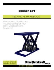
SCISSOR LIFTSSCISSOR LIFTSShop Aid Series Scissor Lifts are a versatileproduction tool. Offered in multiple capacities,these scissor lifts are constructed with qualityin mind and make ideal work stations forassembly or welding processes putting theergonomics of the worker first. Scissor Liftsalso integrate within a conveyor line whenelevation changes are needed.specifications• 2000, 4000 and 6000 lbs. load capacities• 8" lowered height• 24", 36" and 48" travel• 32", 44" and 56" raised height• 1 HP internal power unit standard• Hand pendant controller with 10’ leads• Hand-tool removable pins and bushings forease of maintenance• Guarded foot pedal, external power unitsand accordion skirting available*Expanded product parameters availableABA = Platform WidthB = Platform LengthC = Raised HeightD = Lowered HeightE = TravelCEDScissor Lift Shown in Raised PositionScissor Lift Shown in Lowered PositionLOAD CAPACITY, DIMENSIONAL SPECIFICATIONS AND OPTIONSSERIESLOADCAPACITY(lbs.)LOWEREDHEIGHT(D)TRAVEL(E)RAISEDHEIGHT(C)PLATFORM DIMENSIONS(A x B)<strong>Standard</strong> MaximumLIFTINGSPEEDSTANDARDVOLTAGE/PHASE/HzHS Series24" TravelHS Series36" TravelHS Series48" Travel2000 8" 24" 32" 30" x 50" 54" x 74" 14 sec. 115/1/604000 8" 24" 32" 30" x 50" 54" x 74" 28 sec. 115/1/606000 8" 24" 32" 30" x 50" 54" x 74" 42 sec. 115/1/602000 8" 36" 44" 30" x 54" 54" x 78" 21 sec. 115/1/604000 8" 36" 44" 30" x 54" 54" x 78" 42 sec. 115/1/606000 8" 36" 44" 30" x 54" 54" x 78" 63 sec. 115/1/602000 8" 48" 56" 30" x 66" 54" x 96" 24 sec. 115/1/604000 8" 48" 56" 30" x 66" 54" x 96" 48 sec. 115/1/606000 8" 48" 56" 30" x 66" 54" x 96" 72 sec. 115/1/60OPTIONAL ACCESSORIESFOOT PEDAL HAND PENDANT POWER UNITS LUBE MANIFOLD SKIRTINGMOBILITYPage 30
BALL TABLESBBall Tables are used when products need tobe manually rotated or correctly positioned,such as a work station or other operation thatrequires quick, easy handling of the product.Ball Transfer Tables are also used whentwo or more conveyor lines converge andpackages must be transferred from one lineto another.specifications• Lengths in 1" increments 1' to 12'• Between frame in 1" increments 10" to 48"• 1" diameter stud mount balls• Up to 200 lbs. per foot load capacity• Ceiling supports, floor supports, side guidesand end stops available• Powder coat finishes and galvanizedmaterial available*Expanded product parameters availableABALL TABLESRef.A 10" - 48"B 1' - 12'C 10" - 86"CA = Between Frame (BF)B = Overall Length (OAL)C = Top of BallSpacingBALL PATTERNS AND SPACINGSquarePatternNominalSpacingDiagonalPattern1 13/16"baLL TRANSFER UNIT• 1" diameter main ball• Zinc plated steel construction• 1/4 - 20 stud• 65 lb. per ball transfer load rating1 1/2"Ball SpacingSquare 2", 3", 4", 6"*Diagonal 3", 6"*Values are nominal. 2.8" and 5.7" actual2 3/8"1"Between Frame1/8" <strong>Standard</strong>5/16" Optional7/8"Cross Section for a 2 1/2" x 1" x 12 Ga. Frame1 1/2"Between FrameCross Section for a 3 1/2" x 1 1/2" x 10 Ga. Frame1/4"2 1/2"3 1/2"LOAD CAPACITY CHARTFRAME SIZESUPPORTCENTERFRAMECAPACITYMax. UniformlyDistributed LoadPer Foot (lbs.)BALLCAPACITYMax. Load PerBall5' 2602 1/2" x 1" x 12 ga.10' 35655' 6603 1/2" x 1 1/2" x 10 ga.10' 120Note: Maximum product weight should not exceed 150 lbs. as productmay only rest on 3 ball transfers at one time.Page 31
GRAVITY FLOWRAILBGravity Flowrail Conveyors come in variousconfigurations and are primarily used forstorage racking or installed as a guiderail onanother conveyor. This style of conveyor canalso be floor mounted or elevated with legsto create an independent accumulation line.GRAVITY FLOWRAILspecifications• Lengths in any increment 1' to 12'• Steel, aluminum, white plastic, black plasticand steel with urethane cover wheel options• Powder coat finishes and galvanizedmaterial available*Expanded product parameters availableRef.A 1' - 12'B 3"C 2 11/32" - 2 7/8"BAWheels In LineBA = Overall Length (OAL)B = Wheel SpacingC = Wheel HeightWheels PairedAWheels StaggeredAvailable Style 4 OnlyWHEEL OPTIONSTYPE DIAMETER MATERIAL BEARING CAPACITYSteel 1 15/16" Zinc plated steel Oiled steel ball bearings 50Aluminum 1 15/16" Aluminum Oiled steel ball bearings 50White 1 15/16" Nylon Oiled steel ball bearings 50Black 1 15/16" Nylon Oiled steel ball bearings 50Steel wheel with orange urethane cover 2 3/16"* Zinc plated steel with orange urethane cover Oiled steel ball bearings 50*1/8" thick urethane cover on 1 15/16" diameter wheelLOAD CAPACITIESSUPPORTCENTERSMAXIMUM LOAD PER FOOTStyle 1 Style 2 Style 3 Style 4 Style 53' 179 200* 200* 400* 200*4' 100 168 200* 278 200*5' 62 107 200* 142 1446' 36 74 166 82 837' 22 54 104 51 528' 15 42 70 34 3510' 7 23 35 17 18* Wheel capacity is limiting factorPage 32
2 3/8"3"2 11/32"1 3/4"1 3/4"1 3/4"Style 1U-Channel2 9/32"Style 2J-Channel2 7/8"2 1/2"2 17/32"2"2 13/16"Style 3Opposing Channels2 3/4"Style 4Top HatSTYLE FRAME DESCRIPTION WHEEL ORIENTATION2 7/8"2"1 U-Channel In line2 J-Channel In line3 Opposing Channels In line4 Top Hat Paired or Staggered5 Single Channel In lineStyle 5Single Channel1"Page 33
GRAVITY ROLLER CONVEYORGRAVITY ROLLER CONVEYOR - STRAIGHTGravity Roller Conveyor is a cost effectiveand versatile solution for moving or stagingproducts as well as aiding in the transportof goods to and from areas of distribution ormanufacturing facilities.specifications• Lengths in 1" increments 1' to 12'• Between frame in 1" increments 6" to 55"• 1.4", 1.9", 2.5" and 2.6" rollers• Up to 1000 lbs. per foot load capacity• Ceiling supports, floor supports, side guidesand end stops available• Powder coat finishes and galvanizedmaterial available*Expanded product parameters availableBARef. 1.4" 1.9" 2.5" 2.6"A 10" - 28" 6" - 51" 13" - 55"B 1' - 12'C 9" - 84" 17" - 86"CA = Between Frame (BF)B = Overall Length (OAL)C = Top of Roller (TOR)GRAVITY ROLLER CONVEYOR - CURVEspecifications• 30°, 45°, 60° and 90° turns• Between frame in 1" increments 6" to 55"• 1.4", 1.9", 2.5" and 2.6" rollers• Up to 2500 lbs. total live load capacity• Ceiling supports, floor supports, side guidesand end stops available• Powder coat finishes and galvanizedmaterial available*Expanded product parameters availableRef. 1.4" 1.9" 2.5" 2.6"A 10" - 28" 6" - 51" 13" - 55"B 47", 59" 45.5" - 87" 61" - 99"C 9" - 84" 17" - 86"D 31", 34", 37" 32.5", 48"90°BCAA = Between Frame (BF)B = Outside Radius (OR)C = Top of Roller (TOR)D = Inside Radius (IR)Page 34AD
ROLLER SPECIFICATIONSROLLER DIAMETERAXLE DETAIL TUBE DETAIL ROLLER SPACINGSize TypewallThicknessMAX LOADPER ROLLERMaterial Centers lbs.1.4" 1/4" Round 18 ga. Galvanized 1.5, 3, 4, 4.5, 6, 8, 9,12 941.4" 1/4" Round 18 ga. Aluminum 1.5, 3, 4, 4.5, 6, 8, 9,12 941.9" 7/16" Hex 16 ga. Galvanized 2, 3, 4, 4.5, 6, 8, 9,12 2691.9" 7/16" Hex 16 ga., 13 ga., 9 ga. Mild Steel 2, 3, 4, 4.5, 6, 8, 9,12 2692.5" 11/16" Hex 11 ga. Mild Steel 3, 4, 6, 8, 9,12 6452.6" 11/16" Hex 7 ga. Mild Steel 3, 4, 6, 8, 9,12 6451.9" Taper (2 1/2" - 1 11/16") 7/16" Hex 14 ga. Mild Steel or Zinc Plated 3 2901.4" Taper (1 1/2" - 1") 5/16" Hex 18 ga. Zinc Plated 1.5, 3 150ROLLER DIAMETER ROLLERS HIGH FRAME ROLLERS LOW FRAMEFRAME HEIGHT"E"FRAME TO TOR"F"1.4"2 1/2 x 1 x 12 ga. galvanized steel or 1/8"thick aluminum or powder coated steel4 x 1 x 12 ga. galvanized steel or 1/8" thickaluminum or powder coated steel2 1/2" 3/32"4" -1 13/32"1.9"3 1/2 x 1 1/2 x 10 ga. galvanized or powdercoated steel4 1/2 x 1 1/2 x 10 ga. galvanized or powdercoated steel3 1/2" 1/4"4 1/2" -3/4"2.5", 2.6" 4 x 1 1/2 x 7 ga. powder coated steel 4"1/4"-3/4"END COUPLER AND ROLLER STYLESnon-precision BEARING (NP)Non-Precision bearings are made of a stampedmetal housing with very loose tolerances. They arenot intended for very heavy loads or high speeds.HOOK AND RODFor portable quick disconnectEFROLLERS HIGHEND CAPFor permanent installation applicationsEFROLLERS LOWBridge PLATEFor permanent installation application. Required tohold 1 1/2" spacing across the splice.Page 35
GRAVITY ROLLER SPUR CONVEYORGRAVITY ROLLER CONVEYOR - STRAIGHT AND CURVE SPURAGravity Roller Conveyor is a cost effectiveand versatile solution for moving or stagingproducts as well as aiding in the transportof goods to and from areas of distribution ormanufacturing facilities.specifications• 30°, 45° and 90° spurs• Between frame in 1" increments 10" to 51"• 1.4", 1.9", 2.5" and 2.6" rollers• Ceiling supports, floor supports, side guidesand end stops available• Powder coat finishes and galvanizedmaterial available*Expanded product parameters availableB1.4 1.9 2.5 and 2.6Ref.30° 45° 90° 30° 45° 90° 30° 45° 90°A 10" - 28" 13" - 39" 13" - 51"B 9" - 84" 17" - 86" 17" - 86"C 24", 36", 60" 31", 34", 37" 24", 36", 60" 32.5", 48" 24", 36", 60" 32.5", 48"D* 41" - 108" 34" - 88" 47", 59" 47" - 128" 37" - 99" 45.5", 87" 47" - 128" 37" - 111" 61", 99"E* 20" - 56" 14" - 40" 27" - 49" 26" - 78" 18" - 55" 32" - 65" 26" - 102" 18" - 73" 32" - 78"*Dimensions Approximated* A = Between Frame (BF)B = Top of Roller (TOR)C = Short Rail Length/Inside Radius (IR)D = Long Rail Length/Outside Radius (OR)E = Shelf Bracket LengthSTRAIGHT SPUR30° and 45° onlyCCURVE SPUR90° onlyEEA90°DCDARight HAnd Left Hand Right HAnd Left HandPage 36
ROLLER SPECIFICATIONSROLLER DIAMETERAXLE DETAIL TUBE DETAIL ROLLER SPACINGSize TypewallThicknessMAXIMUMLOAD PERROLLERMaterial Centers lbs.1.4" 1/4" Round 18 ga. Galvanized 3 941.4" 1/4" Round 18 ga. Aluminum 3 941.9" 7/16" Hex 16 ga. Galvanized 3 2691.9" 7/16" Hex 16 ga., 13 ga., 9 ga. Mild Steel 3 2692.5" 11/16" Hex 11 ga. Mild Steel 3 6452.6" 11/16" Hex 7 ga. Mild Steel 3 6451.9" Tapered (2 1/2" - 1 11/16") 7/16" Hex 14 ga. Mild Steel or Zinc Plated 3 2901.4" Tapered (1 1/2" - 1") 5/16" Hex 18 ga. Zinc Plated 3 150ROLLER DIAMETER ROLLERS HIGH FRAME ROLLERS LOW FRAMEFRAME HEIGHT“F”FRAME TO TOR“G”1.4"2 1/2 x 1 x 12 ga. galvanized steel or 1/8"thick aluminum or powder coated steel4 x 1 x 12 ga. galvanized steel or 1/8" thickaluminum or powder coated steel2 1/2 3/324 -1 13/321.9"3 1/2 x 1 1/2 x 10 ga. galvanized or powdercoated steel4 1/2 x 1 1/2 x 10 ga. galvanized or powdercoated steel3 1/2 1/44 1/2 -3/42.5", 2.6" 4 x 1 1/2 x 7 ga. powder coated steel 41/4-3/4END COUPLER AND ROLLER STYLESnon-precision BEARING (NP)Non-Precision bearings are made of a stampedmetal housing with very loose tolerances. They arenot intended for very heavy loads or high speeds.HOOK AND RODFor portable quick disconnectFGROLLERS HIGHEND CAPFor permanent installation applicationsFGROLLERS LOWBridge PLATEFor permanent installation application. Required tohold 1 1/2" spacing across the splice.Page 37
GRAVITY SKATEWHEEL CONVEYORGRAVITY SKATEWHEEL CONVEYOR - STRAIGHTGravity Skatewheel conveyor is an economical,lightweight, non-powered conveyor suitablefor conveying light products and packages.The free-spinning wheels allow products andpackages to be moved manually with minimaleffort. Installed with a slight pitch, gravitytakes over. The light weight construction ofthis conveyor makes it ideal for applicationsrequiring portability.Bspecifications• Lengths in 1" increments 1' to 12'• Overall width in 1" increments 12" to 30"• Steel, aluminum, white plastic, black plastic,and steel with urethane cover wheel options• Up to 200 lbs. per foot load capacity• Ceiling supports, floor supports, side guidesand end stops available• Powder coat finishes and galvanizedmaterial available*Expanded product parameters availableA 12" - 30"B 1' - 12'C 9" - 85"A = Overall Width (OAW)B = Overall Length (OAL)C = Top of Wheel (TOW)AAxle SpacingCGRAVITY SKATEWHEEL CONVEYOR - CURVEspecifications• 30°, 45°, 60° and 90° turns• 30" to 39" inside radius• Overall width in 1" increments 12" to 30"• Steel, aluminum, white plastic, black plastic,and steel with urethane cover wheel options• Up to 600 lbs. total live load capacity• Ceiling supports, floor supports, side guidesand end stops available• Powder coat finishes and galvanizedmaterial*Expanded product parameters availableBA90°CA 12" - 30"B 48", 60"C 9" - 85"D 30" - 39"APage 38DA = Overall Width (OAW)B = Outside Radius (OR)C = Top of Wheel (TOW)D = Inside Radius (IR)
CONVEYOR SPECIFICATIONSWHEEL HEIGHT AXLE SPACINGWHEELS PER FOOTMINIMUMWHEELS PER FOOTMAXIMUMFRAMEFRAME HEIGHT“E”FRAME TO TOW“F”1.5" 12 72Wheels High3" 6 364"* 4 271.5" 12 72Wheels Low3" 6 364"* 4 271.5" 12 72Wheels High3" 6 364"* 4 271.5" 12 72Wheels Low3" 6 364"* 4 27*Only available on straight skatewheel conveyor. Curve spacing is nominal.2 1/2" x 1" x 12 ga., galvanizedsteel or powder coated steel4" x 1" x 12 ga., galvanized steelor powder coated steel2.5" 3/8"4" -1 1/8"2 1/2" x 1" x 1/8" aluminum 2.5" 3/8"4" x 1" x 1/8" aluminum 4" -1 1/8"WHEEL OPTIONSTYPE DIAMETER MATERIAL BEARING CAPACITYSteel 1 15/16" Zinc plated steel Oiled steel ball bearings 50Aluminum 1 15/16" Aluminum Oiled steel ball bearings 50White 1 15/16" Nylon Oiled steel ball bearings 50Black 1 15/16" Nylon Oiled steel ball bearings 50Steel wheel with orange urethane cover 2 3/16"* Zinc plated steel with orange urethane cover Oiled steel ball bearings 50*1/8" thick urethane cover on 1 15/16" diameter wheelLOAD CAPACITY CHARTFRAME MATERIALSUPPORT CENTERSFRAME CAPACITYMaximum Uniformly DistributedLoadWHEEL CAPACITYMaximum Static Load PerWheelSteel 5' 1300 50Steel 10' 350 50Aluminum 5' 710 50Aluminum 10' 160 50END COUPLER STYLESHOOK AND RODFor portable quick disconnectEWHEELS HIGHFEND CAPEFFor permanent installation applicationsWHEELS LOWBridge PLATEFor permanent installation application. Required tohold 1 1/2" spacing across the splice.Page 39
GRAVITY SKATEWHEEL SPURGRAVITY SKATEWHEEL CONVEYOR - STRAIGHT AND CURVE SPURAGravity Skatewheel conveyor is an economical,lightweight, non-powered conveyor suitablefor conveying light products and packages.The free-spinning wheels allow products andpackages to be moved manually with minimaleffort. Installed with a slight pitch, gravity takesover. The light weight of this conveyor makes itideal for portable applications.specifications• 30°, 45° and 90° spurs• Overall width 12", 15", 18", 21", 24" and 30"• Steel, aluminum, white plastic, black plasticand steel with urethane cover wheel options• Up to 600 lbs. total live load capacity• Ceiling supports, floor supports, side guidesand end stops available• Powder coat finishes and galvanizedmaterial available*Expanded product parameters availableB30° 45° 90°A 12", 15", 18", 21", 24", 30"B 9" - 85"C 36", 48", 60"D 53" - 108" 46" - 124" 31"- 37"E 39"- 57" 20" - 46" 34" - 55"* A = Overall Width (OAW)B = Top of Wheel (TOW)C = Short Rail Length / Inside Radius (IR)D = Long Rail Length / Outside Radius (OR)E = Shelf Bracket LengthSTRAIGHT SPUR30° and 45° onlyCCURVE SPUR90° onlyEEA90°DCDARight HAnd Left Hand Right HAnd Left HandPage 40
CONVEYOR SPECIFICATIONSWHEEL HEIGHT AXLE SPACINGWHEELS PER FOOTMINIMUMWHEELS PER FOOTMAXIMUMFRAMEFRAME HEIGHT“F”FRAME TO TOW“G”Wheels High 3" 6 36 2 1/2" x 1" x 12 ga., galvanized steel 2.5" 3/8"Wheels Low 3" 6 36 4" x 1" x 12 ga., galvanized steel 4" -1 1/8"Wheels High 3" 6 36 2 1/2" x 1" x 1/8" aluminum 2.5" 3/8"Wheels Low 3" 6 36 4" x 1" x 1/8" aluminum 4" -1 1/8"WHEEL OPTIONSTYPE DIAMETER MATERIAL BEARING CAPACITYSteel 1 15/16" Zinc plated steel Oiled steel ball bearings 50Aluminum 1 15/16" Aluminum Oiled steel ball bearings 50White 1 15/16" Nylon Oiled steel ball bearings 50Black 1 15/16" Nylon Oiled steel ball bearings 50Steel wheel with orange urethane cover 2 3/16"* Zinc plated steel with orange urethane cover Oiled steel ball bearings 50*1/8" thick urethane cover on 1 15/16" diameter wheelLOAD CAPACITY CHARTFRAME MATERIALSUPPORT CENTERSFRAME CAPACITYMaximum Uniformly DistributedLoadWHEEL CAPACITYMaximum Static Load PerWheelSteel 5' 1300 50Steel 10' 350 50Aluminum 5' 710 50Aluminum 10' 160 50END COUPLER STYLESHOOK AND RODFor portable quick disconnectFWHEELS HIGHGEND CAPFor permanent installation applicationsFWHEELS LOWGBridge PLATEFor permanent installation application. Required tohold 1 1/2" spacing across the splice.Page 41
NOTESPage 42
NOTESPage 43
NOTESPage 44
THE OPTIONSOffered in Powder Coat Finishes and in Galvanized Material Where Applicable*Black111233RAL-9005Safety Blue110552RAL-5019Machinery Grey110652RAL-7011Safety Orange110559RAL-2010Safety Yellow110554RAL-1023Light Ivory115174RAL-1015Gloss White111232RAL-9003<strong>Omni</strong> Blue110549Colors illustrated above may vary slightly from actual paint colors.*Scissor lift tables are available in water base enamel onlyConveyor Green115886Dark Green110555Vista Green110556RAL-6011THE CONTROLSLimitSwitchesE-StopsPhoto EyesIEC MotorStarterAC ControllerCable PullStopJ-BoxesIEC DisconnectSwitchesNot only does <strong>Omni</strong> <strong>Metalcraft</strong> <strong>Corp</strong>. provide flexible, endless standard offering combinations, we excel at custom productsolutions we call, The <strong>Omni</strong> Advantage.Ask your customer service representative for a copy of The <strong>Omni</strong> Advantage or view it on our website.P.O. Box 352 • Alpena, Michigan 49707Phone 989.358.7000Fax 989.358.7020info@omni.comwww.omni.com