MDR Technical Handbook.pdf - Omni Metalcraft Corp.
MDR Technical Handbook.pdf - Omni Metalcraft Corp.
MDR Technical Handbook.pdf - Omni Metalcraft Corp.

Create successful ePaper yourself
Turn your PDF publications into a flip-book with our unique Google optimized e-Paper software.
<strong>MDR</strong> TECHNICAL HANDBOOK 2011.1<br />
<strong>MDR</strong> TECHNICAL HANDBOOK 2011.1
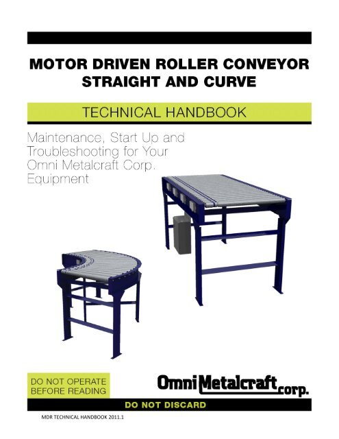
MOTOR DRIVEN ROLLER CONVEYOR STRAIGHT AND CURVE TECH HANDBOOK<br />
TABLE OF CONTENTS<br />
TABLE OF CONTENTS .................................................................................................................................. 2<br />
GENERAL SAFETY STATEMENTS .................................................................................................................. 3<br />
-Introduction ..................................................................................................................................................... 3<br />
-Cautions, Warnings and Hazards ..................................................................................................................... 3<br />
SAFETY INFORMATION ............................................................................................................................... 4<br />
-Safety Labels .................................................................................................................................................... 4, 5<br />
-Installation Safety ............................................................................................................................................ 6<br />
-Electrical Safety ................................................................................................................................................ 7<br />
-Operational Safety ........................................................................................................................................... 8<br />
-Maintenance and Service Safety...................................................................................................................... 9, 10<br />
RECEIVING AND INSPECTION ...................................................................................................................... 11<br />
-Returns, Damages and Shortages ................................................................................................................... 11<br />
-Removal of Crating .......................................................................................................................................... 11<br />
GENERAL INSTALLATION ............................................................................................................................ 12<br />
-Checking Unit Squareness ................................................................................................................................ 12<br />
-Squaring ........................................................................................................................................................... 12<br />
-Coupling / Attaching Bed Sections .................................................................................................................. 13<br />
-Power and Control Wiring Diagram ................................................................................................................. 13<br />
LEG SUPPORTS AND INSTALLATION............................................................................................................ 14<br />
-Permanent Installation of Legs ........................................................................................................................ 14<br />
-Leg Adjustments .............................................................................................................................................. 14<br />
KNEE BRACES, CASTERS AND CEILING HANGERS ........................................................................................ 15<br />
-Installing Knee Braces and Casters .................................................................................................................. 15<br />
-Installing Ceiling Hangers ................................................................................................................................. 16<br />
MULTI-TIER SUPPORTS ............................................................................................................................... 17<br />
-Installation of Multi-Tier Supports ................................................................................................................... 17<br />
PRE-START-UP OVERVIEW .......................................................................................................................... 18<br />
-Preparing for Initial Start-Up ........................................................................................................................... 18<br />
MAINTENANCE .......................................................................................................................................... 19<br />
-Maintenance Schedules ................................................................................................................................... 19<br />
-Report on Miscellaneous Maintenance Performed ......................................................................................... 20<br />
TROUBLESHOOTING AND REPLACEMENT PARTS ........................................................................................ 21<br />
-Motorized Roller ............................................................................................................................................. 21<br />
PARTS LISTS ................................................................................................................................................ 22<br />
-<strong>MDR</strong> Straight .................................................................................................................................................... 22<br />
-<strong>MDR</strong> Curve ....................................................................................................................................................... 23<br />
-Zero-Pressure <strong>MDR</strong> Straight ............................................................................................................................ 24<br />
-Zero-Pressure <strong>MDR</strong> Curve ................................................................................................................................ 25<br />
NOTES ........................................................................................................................................................ 26<br />
WARRANTY ................................................................................................................................................ 27<br />
<strong>MDR</strong> TECHNICAL HANDBOOK 2011.1<br />
2
MOTOR DRIVEN ROLLER CONVEYOR STRAIGHT AND CURVE TECH HANDBOOK<br />
GENERAL SAFETY STATEMENTS<br />
IMPORTANT<br />
REQUIRED READING!<br />
¡IMPORTANTE!<br />
¡LECTURA OBLIGATORIA!<br />
To ensure this quality product is safely and correctly utilized, all instructions within this manual must be read and<br />
understood prior to equipment start-up. Be aware of all safety labels on machinery. If you do not understand<br />
any of the safety instructions or feel there may be safety labels missing, contact your supervisor or product<br />
supplier immediately!<br />
Para garantizar que este producto de calidad se utilice correctamente y con seguridad, es necesario leer y<br />
comprender las instrucciones incluidas en este manual, antes de comenzar a utilizar el equipo. Esté atento a<br />
todas las etiquetas de seguridad que se encuentran en las máquinas. Si no entiende alguna de las instrucciones<br />
de seguridad o considera que faltan algunas etiquetas de seguridad, ¡comuníquese inmediatamente con su<br />
supervisor o proveedor del producto!<br />
COMPLIANCE WITH SAFETY STANDARDS<br />
Compliance with safety standards, including federal, state and local codes or regulations is the responsibility of the conveyor<br />
purchaser(s). Placement of guards, safety labels and other safety equipment is dependent upon the area and use to which the<br />
system is applied. A safety study should be made of the conveyor application by the purchaser(s). It is the purchaser’s<br />
responsibility to provide any additional guards, safety labels or other safety equipment deemed necessary based on this<br />
safety study.<br />
The information contained in this safety manual is correct at the time of printing. Due to the continuing development of<br />
product lines, changes in specifications are inevitable. The company reserves the right to implement such changes without<br />
prior notice.<br />
If you suspect fire hazards, safety hazards, dangers towards health or any other job safety concerns,<br />
consult your federal, state or local codes.<br />
Certain safety information in this document was reprinted from ASME B20.1-2000 by permission of The<br />
American Society of Mechanical Engineers. All rights reserved.<br />
Inspect equipment for safety labels. Make sure personnel are aware of and follow safety instructions.<br />
Maintain an orderly environment in the vicinity of the conveyor at all times. Clean up spilled materials<br />
or lubricants immediately.<br />
All personnel shall be instructed regarding the necessity for continuous care and attention to safety<br />
during the operation of a conveyor. They must be trained to identify and immediately report all unsafe<br />
conditions or practices relating to the conveyor and its operation.<br />
Know your company’s machine specific Lockout / Tagout procedure. Do Not perform maintenance until<br />
electrical disconnect has been turned off!<br />
Replace all safety devices, guards and guarding prior to equipment start-up.<br />
References used for safety instructions in this manual are from: Conveyor Equipment Manufacturers Association (CEMA) and The<br />
American Society of Mechanical Engineers (ASME)<br />
3<br />
<strong>MDR</strong> TECHNICAL HANDBOOK 2011.1
MOTOR DRIVEN ROLLER CONVEYOR STRAIGHT AND CURVE TECH HANDBOOK<br />
SAFETY INFORMATION: SAFETY LABELS<br />
Safety labels have been placed at various points on the equipment to alert everyone of potential dangers. Inspect<br />
equipment for proper position of safety labels and make sure all personnel are aware of the labels and obey their<br />
warnings. As mentioned in the previous section, a safety study should be made of the conveyor application by<br />
the purchaser(s). It is the purchaser’s responsibility to provide any additional guards, safety labels or other<br />
safety equipment deemed necessary based on this safety study. The following pages contain typical safety<br />
labels that may have been attached to your equipment.<br />
#110479 ( 5” x 2 1/2” )<br />
Placed on terminating ends (both ends) where there are exposed<br />
moving parts which must be unguarded to facilitate function, i.e.<br />
rollers, pulleys, shafts, chains, etc.<br />
#113529 (5” X 2 1/2” )<br />
Placed next to drive (both sides) to warn personnel that the lineshaft<br />
conveyor utilizes a rotating shaft which may be hazardous if hair or loose<br />
clothing become entangled around the rotating shaft. Also used on any<br />
other conveyors where the exposed shaft may create similar hazards.<br />
#111744 (5” X 2 1/2” )<br />
General warning to personnel that the equipment’s moving parts,<br />
which operate unguarded by necessity or function, i.e., air cylinders,<br />
etc., create hazards to be avoided.<br />
#110478 ( 5” X 2 1/2” )<br />
Placed on all chain guards to warn that operation of the machinery with<br />
guards removed would expose chains, belts, gears, shafts, pulleys,<br />
couplings, etc. which create hazards.<br />
#111752 ( 5” X 2 1/2” )<br />
Placed on max. of 20’ centers (both sides) along conveyors which<br />
provide surfaces and profiles attractive, but hazardous, for climbing,<br />
sitting, walking or riding.<br />
#113513 ( 5” X 2 1/2” )<br />
Placed on chain guard base so label is visible when guard cover is removed.<br />
#113528 ( 5” X 2 1/2” )<br />
Placed next to drive (both sides) to warn maintenance personnel that<br />
conveyors must be shut off and locked out prior to servicing. Examples:<br />
drives, take-ups, and lubrication points, which require guard removal.<br />
#111870 ( 5” X 3” )<br />
General warning of pinch point hazards.<br />
<strong>MDR</strong> TECHNICAL HANDBOOK 2011.1<br />
4<br />
(Continued on next page)
MOTOR DRIVEN ROLLER CONVEYOR STRAIGHT AND CURVE TECH HANDBOOK<br />
SAFETY INFORMATION: SAFETY LABELS (Continued)<br />
#111750 ( 1 3/4” x 1 1/4” )<br />
Generally placed on smaller guards to<br />
alert personnel of potential danger if<br />
guard is removed and power is not<br />
locked out.<br />
#111749 ( 3” x 1 1/4” )<br />
Placed on shipping brace which stabilizes<br />
equipment during shipping. Brace must be<br />
removed before operating! May cause severe<br />
injury if not removed.<br />
#110491 (10” x 7” )<br />
Placed on equipment where conveyors may<br />
start without warning.<br />
<strong>MDR</strong> TECHNICAL HANDBOOK 2011.1<br />
5
MOTOR DRIVEN ROLLER CONVEYOR STRAIGHT AND CURVE TECH HANDBOOK<br />
SAFETY INFORMATION: INSTALLATION SAFETY<br />
1) LOADING / UNLOADING<br />
Have trained personnel load or unload equipment. The conveyor must be properly handled when transferring<br />
from the unloading area to final site location to prevent damage.<br />
2) GUARDS / GUARDING<br />
Interfacing of Equipment. When two or more pieces of equipment are interfaced, special attention shall be<br />
given to the interfaced area to ensure the presence of adequate guarding<br />
and safety devices.<br />
Guarding Exceptions. Wherever conditions prevail that would require<br />
guarding under this standard but such guarding would render the conveyor<br />
unusable, seek guidance from your safety professional.<br />
3) ANCHORING<br />
DO NOT operate conveyor unless it is properly anchored. Serious injury or death may result.<br />
4) SAFETY WARNING<br />
Install all safety devices, guards and guarding prior to equipment start-up.<br />
<strong>MDR</strong> TECHNICAL HANDBOOK 2011.1<br />
6
MOTOR DRIVEN ROLLER CONVEYOR STRAIGHT AND CURVE TECH HANDBOOK<br />
SAFETY INFORMATION: ELECTRICAL SAFETY<br />
1) ELECTRICAL CODE<br />
All electrical installations and wiring shall conform to federal, state and local codes.<br />
When conveyor operation is not required for a maintenance procedure,<br />
electrical power must be turned off and locked / tagged out following your<br />
company’s machine specific procedure.<br />
2) CONTROL STATION<br />
Control stations should be so arranged and located that the operation of the affected equipment is visible from<br />
them. Control stations shall be clearly marked or labeled to indicate the function controlled.<br />
A conveyor that would cause injury when started shall not be started until personnel in the area are alerted by a<br />
signal or by a designated person that the conveyor is about to start.<br />
Where system function would be seriously hindered or adversely affected by the required time delay, or where<br />
the intent of the warning may be misinterpreted (i.e., a work area with many different conveyors and allied<br />
devices), a clear, concise and legible warning sign needs to be provided. The warning sign shall indicate that<br />
conveyors and allied equipment may be started at any time, that danger exists and that personnel must keep<br />
clear. These warning signs shall be provided along the conveyor at areas not guarded by position or location.<br />
Remotely and automatically controlled conveyors, and conveyors where operator stations are not manned or are<br />
beyond voice or visual contact from drive areas, loading areas, transfer points and other potentially hazardous<br />
locations on the conveyor path not guarded by location, position or guards shall be furnished with emergency stop<br />
buttons, pull cords, limit switches or similar emergency stop devices.<br />
All such emergency stop devices shall be easily identifiable in the immediate vicinity of such locations unless<br />
guarded by location, position or guards. Where the design, function and operation of such conveyor clearly is not<br />
hazardous to personnel, an emergency stop device is not required.<br />
The emergency stop device shall act directly on the control of the conveyor concerned and shall not depend on the<br />
stopping of any other equipment. The emergency stop devices shall be installed so that they cannot be overridden<br />
from other locations.<br />
Inactive and unused actuators, controllers and wiring should be removed from control stations and panel board,<br />
together with obsolete diagrams, indicators, control labels and other material that might confuse the operator.<br />
3) SAFETY DEVICES<br />
All safety devices, including wiring of electrical safety devices, shall be arranged to operate such that a power<br />
failure or failure of the device itself will not result in a hazardous condition.<br />
4) EMERGENCY STOPS AND RESTARTS<br />
Conveyor controls shall be so arranged that, in case of emergency stop, manual reset or start at the location<br />
where the emergency stop was initiated shall be required for the conveyor(s) and associated equipment to<br />
resume operation.<br />
Before restarting a conveyor that has been stopped because of an emergency, an inspection of the conveyor shall<br />
be made and the cause of the stoppage determined. The starting device and electrical power must be turned off<br />
and locked / tagged out according to your company’s machine specific procedure before any attempt is made to<br />
remove the cause of the stoppage, unless operation is necessary to determine the cause or to safely remove the<br />
stoppage.<br />
5) SAFETY WARNING<br />
Replace all safety devices, guards and guarding prior to equipment start-up.<br />
7<br />
<strong>MDR</strong> TECHNICAL HANDBOOK 2011.1
MOTOR DRIVEN ROLLER CONVEYOR STRAIGHT AND CURVE TECH HANDBOOK<br />
SAFETY INFORMATION: OPERATIONAL SAFETY<br />
Only trained, qualified personnel shall be permitted to operate a conveyor. Training shall include instruction in<br />
operation under normal conditions and emergency situations.<br />
Where safety is dependent upon stopping / starting devices, they shall be kept free of obstructions to permit<br />
access.<br />
The area around loading and unloading points shall be kept clear of obstructions that could endanger personnel.<br />
Do not ride the load-carrying element of a conveyor under any<br />
circumstances, unless the conveyor is designed and equipped with<br />
safety and control devices intended to carry personnel. For no<br />
reason shall a person ride any element of a vertical conveyor.<br />
Warning labels reading “DO NOT RIDE CONVEYOR” shall be<br />
affixed by the owner of the conveyor.<br />
Personnel working on or near a conveyor shall be instructed as to the location and operation of pertinent<br />
stopping devices.<br />
A conveyor shall be used to transport only a load that it is designed to handle safely.<br />
Under no circumstances shall the safety characteristics of the conveyor be altered.<br />
Routine inspections and preventative and corrective maintenance programs shall be conducted to ensure<br />
that all safety features and guards are retained and function properly. Inspect equipment for safety labels. Make<br />
sure personnel are aware of and follow safety label instructions.<br />
Alert all personnel to the potential hazard of entanglement in<br />
conveyors caused by items such as long hair, loose clothing and<br />
jewelry.<br />
SAFETY WARNING<br />
Replace all safety devices, guards and guarding prior to<br />
equipment start-up.<br />
<strong>MDR</strong> TECHNICAL HANDBOOK 2011.1<br />
8
MOTOR DRIVEN ROLLER CONVEYOR STRAIGHT AND CURVE TECH HANDBOOK<br />
SAFETY INFORMATION: MAINTENANCE / SERVICE SAFETY<br />
ELECTRICAL POWER MUST BE TURNED OFF AND LOCKED / TAGGED OU T following<br />
your company’s machine specific procedures when servicing conveyor to prevent accidental<br />
restarting by other persons or interconnecting equipment (when used).<br />
1) MAINTENANCE (REPAIR)<br />
Maintenance and service shall be performed by trained, qualified personnel only.<br />
Where lack of maintenance and service would cause a hazardous condition, the user shall establish a<br />
maintenance program to ensure that conveyor components are maintained in a condition that does not<br />
constitute a hazard to personnel.<br />
No maintenance or service shall be performed when a conveyor is in operation. See “Lubrication” and<br />
“Adjustment or Maintenance During Operation” for exceptions.<br />
When a conveyor is stopped for maintenance or service, the starting devices, prime mover, powered<br />
accessories or electrical must be locked / tagged out in accordance with a formalized procedure designed to<br />
protect all persons or groups involved with the conveyor against an unexpected restart. Personnel should be<br />
alerted to the hazard of stored energy, which may exist after the power source is locked out. All safety<br />
devices and guards shall be replaced before starting equipment for normal operation.<br />
2) ADJUSTMENT OR MAINTENANCE DURING OPERATION<br />
When adjustments or maintenance must be done while equipment is in operation, only trained, qualified<br />
personnel who are aware of the hazards of the conveyor in motion shall be allowed to make adjustments,<br />
perform maintenance or service.<br />
Conveyors shall NOT be maintained or serviced while in operation unless proper maintenance or service<br />
requires the conveyor to be in motion. If conveyor operation is required, personnel shall be made aware of<br />
the hazards and how the task may be safely accomplished.<br />
3) LUBRICATION<br />
Conveyors shall NOT be lubricated while in operation unless it is impractical to shut them down for<br />
lubrication. Only trained and qualified personnel who are aware of the hazards of the conveyor in motion<br />
shall be allowed to lubricate a conveyor that is operating.<br />
Where the drip of lubricants or process liquids on the floor constitutes a hazard, drip pans or other means of<br />
eliminating the hazard must be provided by purchaser(s).<br />
4) MAINTENANCE OF GUARDS AND SAFETY DEVICES<br />
Guards and safety devices shall be maintained in a serviceable and operational condition. Warning signs are<br />
the responsibility of the owner of the conveyor and must be maintained in a legible / operational condition.<br />
<strong>MDR</strong> TECHNICAL HANDBOOK 2011.1<br />
9
MOTOR DRIVEN ROLLER CONVEYOR STRAIGHT AND CURVE TECH HANDBOOK<br />
SAFETY INFORMATION: MAINTENANCE / SERVICE SAFETY (Continued)<br />
5) INSPECTIONS<br />
Routine inspections with preventative and /or corrective maintenance programs shall be conducted to ensure<br />
that all safety features and devices are maintained and function properly.<br />
All personnel shall inspect for hazardous conditions at all times. Remove sharp edges or protruding objects.<br />
Repair or replace worn or damaged parts immediately.<br />
6) CLEANING<br />
Where light cleaning and/or casing cleaning are required, they shall be performed by trained personnel. The<br />
conveyor electrical power must be turned off and locked / tagged out following your company’s machine<br />
specific procedures. Special attention may be required at feed and discharge points.<br />
7) SAFETY WARNING<br />
Replace all safety devices, guards and guarding prior to equipment start-up.<br />
<strong>MDR</strong> TECHNICAL HANDBOOK 2011.1<br />
10
MOTOR DRIVEN ROLLER CONVEYOR STRAIGHT AND CURVE TECH HANDBOOK<br />
RECEIVING AND INSPECTION: RETURNS, DAMAGES AND SHORTAGES<br />
UNCRATING CHECKLIST<br />
1) Compare the bill of lading with what you have received (including accessories).<br />
2) Examine the equipment for damage.<br />
3) Immediately report shortage or damages to the vendor and carrier.<br />
4) Obtain a signed damage report from the carrier and send a copy to the vendor.<br />
Do not attempt to modify or repair damaged equipment without authorization from vendor.<br />
Note:<br />
Do not return equipment to the factory without a written return authorization. Returns without written<br />
authorization will not be accepted.<br />
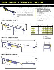
Single section<br />
Multiple sections<br />
Note: Custom products may be crated differently to fit the conveyor design.<br />
MOTOR DRIVEN ROLLER CONVEYOR STRAIGHT AND CURVE TECH HANDBOOK<br />
RECEIVING AND INSPECTION: REMOVAL OF CRATING<br />
AFTER COMPLETING THE “UNCRATING CHECKLIST”<br />
1) Remove crating and packaging.<br />
2) Look for boxes, accessories, bags or components such as fasteners, manuals, guard rails etc. that may be<br />
banded or fastened to the crating material.<br />
Note: Make sure all fasteners, guards and essential components are not discarded.<br />
<strong>MDR</strong> TECHNICAL HANDBOOK 2011.1<br />
11
MOTOR DRIVEN ROLLER CONVEYOR STRAIGHT AND CURVE TECH HANDBOOK<br />
GENERAL INSTALLATION: CHECKING UNIT SQUARENESS<br />
SQUARING<br />
Frame squareness can be checked by using a simple right angle square as shown or by measuring from the same<br />
points diagonally, corner to corner.<br />
Note:<br />
Make sure frames are square<br />
(as shown) or products will<br />
skew and tumble from the<br />
conveyor. Failure to square<br />
frames may also cause<br />
premature conveyor wear<br />
and failure.<br />
MOTOR DRIVEN ROLLER CONVEYOR STRAIGHT AND CURVE TECH HANDBOOK<br />
GENERAL INSTALLATION: SQUARING<br />
USING TURNBUCKLES TO SQUARE CONVEYOR<br />
Bolt-together conveyor frames may be brought square by means of attaching turnbuckles to each corner and<br />
turning them down appropriately until square.<br />
SQUARING RODS<br />
Note:<br />
Only trained professionals<br />
should attempt to square up<br />
a conveyor. If frames have<br />
been damaged in freight,<br />
follow the “returns, damages<br />
and shortages” protocol on<br />
page 11.<br />
TURNBUCKLES<br />
<strong>MDR</strong> TECHNICAL HANDBOOK 2011.1<br />
12
MOTOR DRIVEN ROLLER CONVEYOR STRAIGHT AND CURVE TECH HANDBOOK<br />
GENERAL INSTALLATION: COUPLING / ATTACHING BED SECTIONS<br />
COUPLING<br />
1) Prior to coupling the conveyor sections, make sure that the drive cards are all on the same side of each<br />
conveyor.<br />
2) Couple the sections using bolts provided per the drawing below.<br />
Note:<br />
For ease of installation, mount legs on each conveyor section prior to coupling.<br />
MOTOR DRIVEN ROLLER CONVEYOR STRAIGHT AND CURVE TECH HANDBOOK<br />
GENERAL INSTALLATION: POWER AND CONTROL WIRING DIAGRAM<br />
RETRO-REFLECTIVE PHOTO-EYE<br />
DEFINES DOWNSTREAM<br />
EDGE OF A ZONE<br />
MOTORIZED ROLLER<br />
24 VDC BRUSHLESS<br />
MOTOR<br />
COMMUNICATION CABLE<br />
<strong>MDR</strong> TECHNICAL HANDBOOK 2011.1<br />
13<br />
24 VDC AND<br />
CONTROL LINES<br />
POWER CABLE
MOTOR DRIVEN ROLLER CONVEYOR STRAIGHT AND CURVE TECH HANDBOOK<br />
LEG SUPPORTS AND INSTALLATION<br />
PERMANENT INSTALLATION OF LEGS<br />
Secure leg supports to the floor utilizing the lag holes in the adjustable leg boot.<br />
SIDE FRAMES<br />
Note:<br />
Make sure the conveyor is<br />
level by placing a level on the<br />
conveyor side frames. If the<br />
conveyor is not level, adjust<br />
the legs appropriately as<br />
shown below.<br />
LAG HOLES<br />
LEG ADJUSTMENT: BOLT-TOGETHER LEGS<br />
1) The conveyor electrical power must be turned off and<br />
locked / tagged out following your company’s machine<br />
specific procedures.<br />
2) Remove all load from the conveyor.<br />
3) Position conveyor in the location to be installed.<br />
4) Support conveyor section with jack, hoist or forklift.<br />
5) Carefully loosen the fasteners within the slots.<br />
6) Lift or lower conveyor until it is at the desired height.<br />
7) Ensure that the conveyor is completely level. (reference<br />
leveling note below)<br />
8) Tighten fasteners using torque appropriate for each<br />
fastener’s size and grade. (grade 5 fasteners provided)<br />
HEX HEAD<br />
CAP SCREWS<br />
PIVOT<br />
BRACKET<br />
UPRIGHT<br />
BOOT<br />
Note:<br />
Only qualified installation<br />
professionals should level<br />
and install conveyor.<br />
<strong>MDR</strong> TECHNICAL HANDBOOK 2011.1<br />
14
MOTOR DRIVEN ROLLER CONVEYOR STRAIGHT AND CURVE TECH HANDBOOK<br />
KNEE BRACES, CASTERS AND CEILING HANGERS: INSTALLING KNEE BRACES<br />
INSTALLING KNEE BRACES<br />
1) After leg supports are set in place, attach the<br />
brace bracket.<br />
2) Attach knee brace angle to the leg support<br />
and brace bracket.<br />
(Knee brace angle may need to be cut, drilled and<br />
trimmed for proper fit and to eliminate<br />
interference with adjacent equipment)<br />
Note:<br />
Knee braces are recommended when the<br />
conveyor height exceeds 36” and/or when<br />
additional stability is needed.<br />
DETAIL DESCRIPTION<br />
1 UPRIGHT<br />
2 SPREADER<br />
3 BRACE BRACKET<br />
4 KNEE BRACE ANGLE<br />
5 PIVOT BRACKET<br />
6 FOOT<br />
7 HEX HEAD CAP SCREW<br />
MOTOR DRIVEN ROLLER CONVEYOR STRAIGHT AND CURVE TECH HANDBOOK<br />
KNEE BRACES, CASTERS AND CEILING HANGERS: INSTALLING CASTERS<br />
NOTE: CUSTOMER TO LOCATE<br />
AND DRILL IF NECSSARY<br />
INSTALLING CASTERS<br />
Once in position, casters<br />
should be locked until<br />
conveyor needs to be<br />
moved again.<br />
Note:<br />
Leg supports with casters<br />
follow similar installation<br />
instructions as standard leg<br />
supports and knee braces.<br />
<strong>MDR</strong> TECHNICAL HANDBOOK 2011.1<br />
15<br />
DETAIL DESCRIPTION<br />
1 UPRIGHT<br />
2 SPREADER<br />
3 BRACE BRACKET<br />
4 KNEE BRACE ANGLE<br />
5 PIVOT BRACKET<br />
6 FOOT<br />
7 Z-PLATE<br />
8 PHENOLIC CASTER<br />
9 HEX HEAD CAP SCREW
MOTOR DRIVEN ROLLER CONVEYOR STRAIGHT AND CURVE TECH HANDBOOK<br />
KNEE BRACES, CASTERS AND CEILING HANGERS: INSTALLING CEILING HANGERS<br />
INSTALLING CEILING HANGERS<br />
When using conveyors in an overhead scenario, mount hangers at section joints.<br />
Note:<br />
When installing ceiling hangers,<br />
refer to local building codes to<br />
ensure that materials comply.<br />
Only experienced material handling<br />
installers should attempt to install<br />
conveyors.<br />
CONVEYOR SECTION<br />
DETAIL DESCRIPTION<br />
1 HANGER CHANNEL<br />
2 PIPE SPREADER<br />
3 THREADED ROD<br />
4 U-BOLT<br />
5 WHIZ NUT<br />
6 HEX HEAD CAP SCREW<br />
7 HEX NUT<br />
8 LOCK WASHER<br />
<strong>MDR</strong> TECHNICAL HANDBOOK 2011.1<br />
16
MOTOR DRIVEN ROLLER CONVEYOR STRAIGHT AND CURVE TECH HANDBOOK<br />
MULTI-TIER SUPPORTS: INSTALLATION OF MULTI-TIER SUPPORTS<br />
INSTALLING MULTI-TIER SUPPORTS<br />
1) Remove the upper spreader (detail 2) from support.<br />
2) Lower the conveyor section onto the lower spreader (detail 2) and attach using supplied fasteners.<br />
3) Check for appropriate elevation and attach the knee bracket assembly (detail 3,4,6,7,8).<br />
4) For upper conveyor assembly, replace upper spreader and repeat steps 2 and 3.<br />
5) Make sure all multi-tier supports are in line and square prior to conveyor start-up.<br />
Note: Make sure that the conveyor is stable prior to<br />
multi-tier assembly. Use of a forklift or crane may be<br />
required to ensure safe handling. Only experienced<br />
installation professionals should install conveyor.<br />
DETAIL DESCRIPTION<br />
1 UPRIGHT<br />
2 SPREADER<br />
3 BRACE BRACKET<br />
4 KNEE BRACE ANGLE<br />
5 FOOT WELDMENT<br />
6 WHIZ NUT<br />
7 HEX HEAD CAP SCREW<br />
8 FLAT WASHER<br />
<strong>MDR</strong> TECHNICAL HANDBOOK 2011.1<br />
17
MOTOR DRIVEN ROLLER CONVEYOR STRAIGHT AND CURVE TECH HANDBOOK<br />
PRE-START-UP OVERVIEW: PREPARING FOR INITIAL START-UP<br />
1) Review pages 7 and 8 prior to starting any equipment.<br />
2) Verify that conveyor sections, leg supports, etc. were installed properly.<br />
3) Verify that all zone-to-zone cabling is connected properly.<br />
4) Verify that all sensor cabling is connected properly.<br />
5) Verify that conveyor is not loaded with product.<br />
6) Verify drive rollers are securely bolted to side frame.<br />
7) Verify all slave rollers are attached to drive roller with proper drive bands.<br />
8) Check all drive rollers, photo-eyes and drive modules for proper wiring.<br />
9) Check all drive module DIP switch settings. (DIP switches must be set before supplying power to drive<br />
modules)<br />
<strong>MDR</strong> TECHNICAL HANDBOOK 2011.1<br />
18
MOTOR DRIVEN ROLLER CONVEYOR STRAIGHT AND CURVE TECH HANDBOOK<br />
MAINTENANCE: MAINTENANCE SCHEDULES<br />
Note:<br />
Review pages 9 and 10 prior to performing maintenance on any equipment.<br />
WEEKLY MAINTENANCE<br />
Unit Safety Check<br />
Confirm placement of all warning labels. Check for loose bolts, unrestrained wiring, loose wiring connectors,<br />
nip points and other hazards.<br />
MONTHLY MAINTENANCE<br />
Belt Tension<br />
Check for consistent belt tension between rollers and replace belts as needed.<br />
QUARTERLY MAINTENANCE<br />
Drive Rollers<br />
Ensure that drive roller is operating within its proper heat and noise range.<br />
<strong>MDR</strong> TECHNICAL HANDBOOK 2011.1<br />
19
MOTOR DRIVEN ROLLER CONVEYOR STRAIGHT AND CURVE TECH HANDBOOK<br />
MAINTENANCE: REPORT ON MISCELLANEOUS MAINTENANCE PERFORMANCE<br />
REPORT ON MISCELLANEOUS MAINTENANCE PERFORMANCE<br />
Date___________<br />
Maintenance Performed:<br />
____________________________________________________________________________________________<br />
____________________________________________________________________________________________<br />
____________________________________________________________________________________________<br />
<strong>MDR</strong> TECHNICAL HANDBOOK 2011.1<br />
20
MOTOR DRIVEN ROLLER CONVEYOR STRAIGHT AND CURVE TECH HANDBOOK<br />
TROUBLESHOOTING AND REPLACEMENT PARTS: MOTORIZED ROLLER<br />
MOTORIZED ROLLER<br />
PROBLEM CAUSE SOLUTION<br />
Drive roller running excessively<br />
hot or repeatedly stalling<br />
Drive belt slipping<br />
Broken belt<br />
Drive roller fault condition<br />
Electrical<br />
Zone overloaded<br />
Insufficient belt<br />
tension/type<br />
Worn or damaged belt<br />
Insufficient belt<br />
tension/type<br />
Check wiring and circuits, take ampere reading,<br />
replace drive roller if necessary<br />
Check conveyor for excessive load, reduce if<br />
design specifications are exceeded<br />
Replace belt with original equipment<br />
manufacturer belt<br />
Replace broken belt with original equipment<br />
manufacturer belt<br />
Replace belt with original equipment<br />
manufacturer belt<br />
<strong>MDR</strong> TECHNICAL HANDBOOK 2011.1<br />
21
MOTOR DRIVEN ROLLER CONVEYOR STRAIGHT AND CURVE TECH HANDBOOK<br />
PARTS LISTS: <strong>MDR</strong> STRAIGHT<br />
DETAIL<br />
DESCRIPTION<br />
1 SIDEFRAME<br />
2 BOLT-IN SPREADER<br />
3 END COUPLER<br />
4 MOTORIZED DRIVE ROLLER<br />
5 GROOVED ROLLER: 2 GROOVES<br />
6 URETHANE SLAVE BAND<br />
7 DRIVE CARD MODULE<br />
8 HEX HEAD CAP SCREW<br />
9 CARRIAGE BOLT<br />
10 NYLOCK NUT<br />
11 WHIZ NUT<br />
12 JAM NUT<br />
<strong>MDR</strong> TECHNICAL HANDBOOK 2011.1<br />
22
MOTOR DRIVEN ROLLER CONVEYOR STRAIGHT AND CURVE TECH HANDBOOK<br />
PARTS LISTS: <strong>MDR</strong> CURVE<br />
DETAIL<br />
DESCRIPTION<br />
1 OUTSIDE RAIL<br />
2 INSIDE RAIL<br />
3 BOLT-IN SPREADER<br />
4 END COUPLER<br />
5 MOTORIZED DRIVE ROLLER<br />
6 GROOVED TAPERED ROLLER: 2 GROOVES<br />
7 URETHANE DRIVE BAND<br />
8 URETHANE SLAVE BAND<br />
9 DRIVE CARD MODULE<br />
10 HEX HEAD CAP SCREW<br />
11 CARRIAGE BOLT<br />
12 NYLOCK NUT<br />
13 WHIZ NUT<br />
14 JAM NUT<br />
<strong>MDR</strong> TECHNICAL HANDBOOK 2011.1<br />
23
MOTOR DRIVEN ROLLER CONVEYOR STRAIGHT AND CURVE TECH HANDBOOK<br />
PARTS LISTS: ZERO-PRESSURE <strong>MDR</strong> STRAIGHT<br />
DETAIL<br />
DESCRIPTION<br />
1 SIDEFRAME<br />
2 BOLT-IN SPREADER<br />
3 END COUPLER<br />
4 MOTORIZED DRIVE ROLLER<br />
5 GROOVED ROLLER: 2 GROOVES<br />
6 URETHANE SLAVE BAND<br />
7 DRIVE CARD MODULE<br />
8 POWER SUPPLY BRACKET<br />
9 REFLECTOR<br />
10 PHOTO-EYE<br />
11 PHOTO-EYE BRACKET<br />
12 METAL FRAMING CHANNEL<br />
13 REFLECTOR BRACKET<br />
14 POWER SUPPLY<br />
15 RUBBER GROMMET<br />
16 CHANNEL LOCK NUT<br />
17 HEX HEAD CAP SCREW<br />
18 CARRIAGE BOLT<br />
19 WHIZ NUT<br />
20 JAM NUT<br />
21 PHOTO-EYE NUT<br />
<strong>MDR</strong> TECHNICAL HANDBOOK 2011.1<br />
24
MOTOR DRIVEN ROLLER CONVEYOR STRAIGHT AND CURVE TECH HANDBOOK<br />
PARTS LISTS: ZERO-PRESSURE <strong>MDR</strong> CURVE<br />
DETAIL<br />
DESCRIPTION<br />
1 OUTSIDE RAIL<br />
2 INSIDE RAIL<br />
3 BOLT-IN SPREADER<br />
4 END COUPLER<br />
5 MOTORIZED DRIVE ROLLER<br />
6 GROOVED TAPERED ROLLER: 2 GROOVES<br />
7 URETHANE DRIVE BAND<br />
8 URETHANE SLAVE BAND<br />
9 DRIVE CARD MODULE<br />
10 REFLECTOR BRACKET<br />
11 REFLECTOR<br />
12 PHOTO-EYE<br />
13 PHOTO-EYE NUT<br />
14 PHOTO-EYE BRACKET<br />
15 HEX HEAD CAP SCREW<br />
16 CARRIAGE BOLT<br />
17 NYLOCK NUT<br />
18 WHIZ NUT<br />
19 JAM NUT<br />
<strong>MDR</strong> TECHNICAL HANDBOOK 2011.1<br />
25
MOTOR DRIVEN ROLLER CONVEYOR STRAIGHT AND CURVE TECH HANDBOOK<br />
NOTES<br />
Notes:<br />
___________________________________________________<br />
___________________________________________________<br />
___________________________________________________<br />
___________________________________________________<br />
___________________________________________________<br />
___________________________________________________<br />
___________________________________________________<br />
___________________________________________________<br />
___________________________________________________<br />
___________________________________________________<br />
___________________________________________________<br />
___________________________________________________<br />
___________________________________________________<br />
___________________________________________________<br />
___________________________________________________<br />
___________________________________________________<br />
___________________________________________________<br />
___________________________________________________<br />
___________________________________________________<br />
___________________________________________________<br />
___________________________________________________<br />
___________________________________________________<br />
___________________________________________________<br />
___________________________________________________<br />
___________________________________________________<br />
___________________________________________________<br />
___________________________________________________<br />
___________________________________________________<br />
___________________________________________________<br />
___________________________________________________<br />
___________________________________________________<br />
___________________________________________________<br />
___________________________________________________<br />
___________________________________________________<br />
___________________________________________________<br />
___________________________________________________<br />
<strong>MDR</strong> TECHNICAL HANDBOOK 2011.1<br />
26
MOTOR DRIVEN ROLLER CONVEYOR STRAIGHT AND CURVE TECH HANDBOOK<br />
WARRANTY REFERENCE<br />
<strong>Omni</strong> <strong>Metalcraft</strong> <strong>Corp</strong>. warrants that the Equipment will be free of defects in workmanship and material (if<br />
properly installed, operated and maintained) for a period of one year or 2080 hours of use, whichever is sooner,<br />
from date of shipment to Customer, subject to the limitations hereunder set forth. If within the one year<br />
warranty period, <strong>Omni</strong> receives from the Customer written notice of any alleged defects in the Equipment and if<br />
the Equipment is not found to be in conformity with this warranty (the Customer having provided <strong>Omni</strong> a<br />
reasonable opportunity to perform any appropriate tests thereon) <strong>Omni</strong> will, at its option, either repair the<br />
Equipment or supply a replacement therefore.<br />
*The above stated information is in reference to a section of <strong>Omni</strong> <strong>Metalcraft</strong>’s full Terms and Conditions of sale. This information does not<br />
constitute an agreement, but simply reference information. To obtain a full copy of <strong>Omni</strong> <strong>Metalcraft</strong>’s Terms and Conditions of Sale, please<br />
contact your Sales Representative.<br />
<strong>MDR</strong> TECHNICAL HANDBOOK 2011.1<br />
27
<strong>MDR</strong> TECHNICAL HANDBOOK 2011.1<br />
28