Range Rover Workshop Manual - System Description and Operation ...
Range Rover Workshop Manual - System Description and Operation ...
Range Rover Workshop Manual - System Description and Operation ...

You also want an ePaper? Increase the reach of your titles
YUMPU automatically turns print PDFs into web optimized ePapers that Google loves.
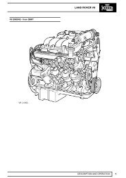
ENGINE – TD6The oil pump is driven from the crankshaft by a chain <strong>and</strong> sprocket system. Pressurised oil from the pump is passedthrough a port in the bottom of the cylinder block <strong>and</strong> is directed up to the oil inlet port of the oil cooler <strong>and</strong> filter housingvia a port in the RH side of the cylinder block. The oil pump contains an oil pressure relief valve which opens to allowoil to be recirculated back around the pump if the oil pressure increases to a high enough level.The inlet port of the oil cooler <strong>and</strong> filter housing has an integral non-return valve which allows flow into the filter, butprevents unfiltered oil draining back out of the filter housing when oil pressure is reduced.The oil passes through the oil filter element <strong>and</strong> out to the oil cooler. The percentage of oil flow passed through to theoil cooler is dependent on a thermostatic by-pass valve which is integrated into the oil filter housing. An increase inoil temperature causes the by-pass valve to open <strong>and</strong> allow a greater percentage of oil flow to be directed through theoil cooler. The remainder of the oil flow from the outlet side of the filter element is directed to the outlet port of the oilfilter housing where it combines with the oil flow being returned from the oil cooler before being passed back into thecylinder block.An oil pressure switch is included in the outlet port of the oil filter housing to sense the oil pressure level before the oilflow enters the main oil gallery in the engine block. A warning lamp in the instrument pack is switched on if the oilpressure is detected to be too low.For more information on the oil pressure warning lamp refer to the Instruments section of this workbook.Oil entering the cylinder block main gallery passes through drillings to the crankshaft main bearings <strong>and</strong> cross drillingsin the crankshaft direct oil to the big-end bearings. An additional four drillings in the cylinder block supply oil at reducedpressure to the lubrication jets for piston <strong>and</strong> cylinder cooling <strong>and</strong> gudgeon pin lubrication.A cross channel from the LH main oil gallery crosses to the RH side of the cylinder block where there is an outlet portwhich provides a pressurised oil supply to the turbocharger bearings via a banjo connection <strong>and</strong> external piping.Riser channels at the front RH side <strong>and</strong> rear LH side of the cylinder block are used to channel oil to mating ports inthe cylinder head <strong>and</strong> provide a source for cylinder head lubrication <strong>and</strong> operating pressure for the lash adjusters.Oil is fed through oil galleries at the LH <strong>and</strong> RH side of the engine <strong>and</strong> six cross channels from each gallery directsoil to the camshaft bearings. Lubrication oil fed to the lash adjusters passes up through the lash adjuster's body to thefinger rockers for lubrication of the surfaces between the finger rockers <strong>and</strong> the camshaft lobes.Tapered plugs seal the cylinder head oil galleries at the rear of the cylinder head, <strong>and</strong> an additional tapered plug isincluded inside the cylinder head at the front of the RH gallery.An additional riser channel from the cylinder block LH main oil gallery is used to supply lubrication to the timing chainsystem through several outlet ports at the front of the cylinder block <strong>and</strong> cylinder head.12-1-14 DESCRIPTION AND OPERATION