Range Rover Workshop Manual - Eng - Landiesrus
Range Rover Workshop Manual - Eng - Landiesrus
Range Rover Workshop Manual - Eng - Landiesrus

Create successful ePaper yourself
Turn your PDF publications into a flip-book with our unique Google optimized e-Paper software.
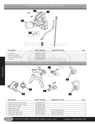
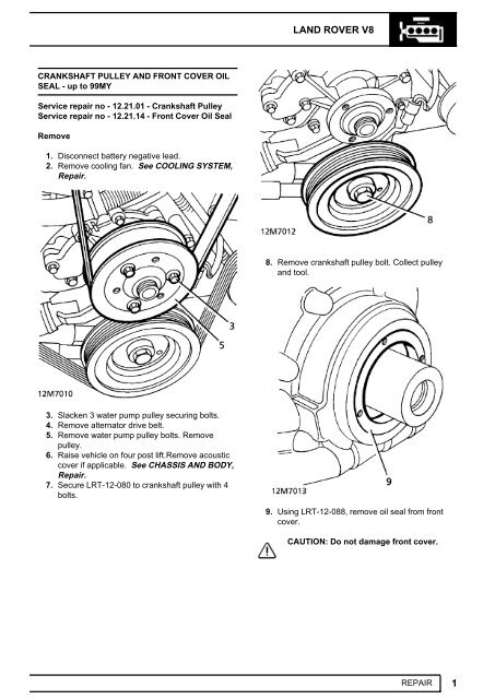
12ENGINE NEW RANGE ROVERRefit10. Clean seal register and crankshaft pulley.11. Lubricate outer face of seal.12. Using LRT-12-089, fit seal to cover.13. Lubricate oil seal lip. Fit crankshaft pulley.14. Refit crankshaft pulley bolt. Tighten to 270 Nm(200 lbf.ft)15. Ensure mating faces between flywheel accesscover and gearbox are clean.16. Lower vehicle.17. Ensure mating faces between water pump pulleyand pump are clean.18. Refit water pump pulley. Tighten to 22 Nm (16lbf.ft)19. Refit alternator drive belt.20. Refit cooling fan. See COOLING SYSTEM,Repair.21. Reconnect battery negative lead.CRANKSHAFT PULLEY AND FRONT COVER OILSEAL - from 99MYService repair no - 12.21.01 Crankshaft pulleyService repair no - 12.21.14 Front cover oil sealRemove1. Remove auxiliary drive belt. See ELECTRICAL,Repair.2. Secure LRT-12-080 to crankshaft pulley with 2bolts.3. Remove crankshaft pulley bolt.4. Remove crankshaft pulley.5. Using LRT-12-088, remove oil seal from frontcover.Refit6. Clean seal register in front cover and crankshaftpulley.2 REPAIR
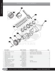
LAND ROVER V8CRANKSHAFT REAR OIL SEALService repair no - 12.21.20Remove1. <strong>Manual</strong> Vehicles: Remove flywheel. See thissection.2. Automatic Vehicles: Remove drive plate. Seethis section.7. Lubricate outer face of seal and fit seal to frontcover using LRT-12-0898. Fit crankshaft pulley and tighten bolt to 270 Nm(200 lbf.ft.).9. Remove LRT-12-080 from crankshaft pulley.10. Fit auxiliary drive belt. See ELECTRICAL,Repair.3. Remove oil seal from location.RefitCAUTION: Do not damage seal location orrunning surface on crankshaft.4. Ensure both seal location and running surfaceon crankshaft are clean.5. Ensure mating faces of flywheel and crankshaftare clean.6. Lubricate seal guide LRT-12-095 with cleanengine oil. Position over crankshaft boss.REPAIR3
12ENGINE NEW RANGE ROVERDRIVE PLATE - AUTOMATIC - up to 99MYService repair no - 12.53.13Remove1. Remove automatic gearbox and torqueconverter. See AUTOMATIC GEARBOX,Repair.7. Lubricate oil seal lip.8. Position seal squarely. Remove guide.9. Drift seal into location using LRT-12-091.10. <strong>Manual</strong> Vehicles: Fit flywheel. See thissection.11. Automatic Vehicles: Fit drive plate. See thissection.2. Remove 4 clamp ring bolts. Collect clamp ring.3. Remove flexible drive plate/starter ring gearassembly from hub aligner.4. Remove 6 screws from hub aligner. Remove hubaligner from crankshaft. Collect spacer.5. Check drive plate for distortion or cracks. Checkstarter ring gear for chipped or broken teeth. Ifeither component shows signs of damage, fit anew assembly.4 REPAIR
LAND ROVER V8Refit6. Ensure all mating surfaces are clean.7. Fit spacer and hub aligner to crankshaft.8. Fit hub aligner screws. Tighten to 85 Nm (63lbf.ft)9. Fit drive plate and clamp ring.10. Fit clamp ring bolts. Tighten to 45 Nm (33 lbf.ft)11. Fit automatic gearbox and converter assembly.See AUTOMATIC GEARBOX, Repair.DRIVE PLATE - AUTOMATIC - from 99MYService repair no - 12.53.13Remove1. Remove gearbox. See AUTOMATICGEARBOX, Repair.2. Remove CKP sensor. See FUEL SYSTEM,Repair.3. Remove Lucar from starter solenoid.4. Remove nut securing battery lead to startersolenoid and disconnect lead.5. Remove 2 Allen screws securing starter motorand remove starter motor.6. Remove 4 bolts securing drive plate clamp ringand remove ring.7. Remove drive plate from hub.8. Remove spacer.9. Remove starter ring gear.REPAIR5
12ENGINE NEW RANGE ROVERRefit10. Clean starter ring gear and hub, clean dowel anddowel hole.11. Fit starter ring gear to hub.12. Clean spacer, clamp ring and mating face onhub.13. Clean drive plate and check for cracks anddistortion.14. Fit spacer to hub, fit drive plate and clamp ring.Tighten bolts to 45 Nm (33 lbf.ft).15. Clean starter motor and mating face.16. Fit starter motor and tighten Allen screws to 45Nm (33 lbf.ft).17. Connect battery lead to starter solenoid andsecure with nut.18. Connect lucar to starter solenoid.19. Fit CKP sensor. See FUEL SYSTEM, Repair.20. Fit gearbox. See AUTOMATIC GEARBOX,Repair.6 REPAIR
LAND ROVER V8ENGINE AND GEARBOX - up to 99MYService repair no - 12.37.01/99Remove1. Position vehicle on four post lift.2. Remove battery. See ELECTRICAL, Repair.3. Remove ECM. See FUEL SYSTEM, Repair.4. Remove 2 screws securing engine harnessclamp to battery tray. Collect clamp.5. Release starter feed wire from battery terminalclamp.6. Release earth lead from alternator bracket.7. Release fuel return hose clip. Release fuel returnhose from regulator connecting pipe.8. Release fuel feed pipe from fuel rail.9. Disconnect multiplug from purge valve.10. Release purge hose from ram pipe housing.11. Remove purge valve securing bolt from shockabsorber turret. Place valve aside.12. Disconnect multiplug from air flow meter.13. Release harness from intake hose.14. Slacken clip securing intake hose to plenumchamber.15. Remove intake hose/air flow meter assembly.16. Position harness across engine.17. Disconnect throttle and cruise control cablesfrom throttle linkage.18. Release cables from abutment bracket.19. Disconnect top hose from inlet manifold.20. Disconnect heater hose from inlet manifold.Release hose from clip. Place hose aside.21. Disconnect coolant hose from plenum chamberwater jacket. Release hose from 2 clips. Placehose aside on valance.22. Remove 4 bolts securing battery tray. Removebattery tray.REPAIR7
12ENGINE NEW RANGE ROVER23. Remove 2 bolts securing fuse box. Pivot fusebox for access.24. Disconnect engine harness multiplug from baseof fuse box.25. Release earth wire from valance stud.26. Disconnect 2 engine harness multiplugs frommain harness.27. Release engine harness clip from valance. Tieharness aside over engine.28. With assistance, release bonnet struts from bodylocations. Retain bonnet in vertical position usingstay clips.29. Depressurise fuel system. See FUEL SYSTEM,Repair.30. Remove air cleaner. See FUEL SYSTEM,Repair.31. Drain cooling system. See COOLING SYSTEM,Repair.32. Discharge air conditioning system. See AIRCONDITIONING, Adjustment.33. Remove cooling fan and viscous coupling. SeeCOOLING SYSTEM, Repair.34. Remove front grille. See CHASSIS AND BODY,Repair.35. Remove 4 bolts securing bonnet platform.WARNING: Only open the bonnet to thevertical position with the vehicle on ahorizontal surface in the workshop. Thisposition is not intended to be used outdoorswhere the bonnet could be affected by winds.36. Release straps securing bonnet release cable toplatform. Remove platform.37. Remove 2 studs securing each radiator airdeflector. Remove both deflectors.8 REPAIR
LAND ROVER V838. Remove bolt and screw securing washer bottlefiller neck. Remove filler neck.41. Release 2 fog lamp breather hoses from clips oneither side of radiator.42. Disconnect 3 coolant hoses from thermostathousing.43. Remove 2 bolts securing power steering fluidreservoir to radiator.CAUTION: Where pipes are disconnected,plug pipes and ports to prevent ingress ofdirt.39. Disconnect engine and gearbox oil coolers.Remove ’O’ rings and discard. Tie pipes asideon engine.NOTE: Position container beneath powersteering reservoir to catch spillage.44. Disconnect return pipe from reservoir. Tiereservoir aside to engine.45. Disconnect feed pipe from power steering pump.Remove ’O’ rings and discard.40. Disconnect coolant bleed hose from radiator.REPAIR9
12ENGINE NEW RANGE ROVER46. Release feed pipe clip from bracket. Place pipeaside.47. Disconnect multiplug from gearbox oiltemperature sensor.48. Disconnect 2 pipes from air conditioningcondenser. Remove ’O’ rings and discard.49. Disconnect 2 pipes from air conditioningcompressor. Remove ’O’ rings and discard.Place pipes aside.50. Remove 2 nuts and bolts securing radiatormountings to chassis.51. With assistance, raise radiator assembly foraccess to condenser cooling fan connections.<strong>Manual</strong> Vehicles:58. Remove centre console. See CHASSIS ANDBODY, Repair.59. Remove 6 nuts securing gaiter ring. Removering and gaiter.60. Remove 2 bolts securing gear lever. Removelever.52. Disconnect 2 condenser cooling fan multiplugs.53. With assistance, remove radiator/condenser/oilcooler assembly.<strong>Manual</strong> Vehicles:54. Clamp clutch flexible hose using an approvedbrake hose clamp.55. Remove clip securing flexible hose to gearboxbracket.56. Disconnect clutch flexible hose at gearbox pipe.Position hose aside.Automatic Vehicles:All Vehicles:61. Release handbrake. Release handbrake cableclevis pin.57. Remove window switch pack. SeeELECTRICAL, Repair.10 REPAIR
LAND ROVER V862. Raise lift. Drain gearbox, transfer box andengine fluids. See SECTION 10, Maintenance.63. Using a transmission jack, support transmissionunder brake drum.64. Remove exhaust front pipe. See MANIFOLDAND EXHAUST SYSTEM, Repair.65. Release hand brake cable from grommet intunnel.66. Remove 4 bolts securing rear propeller shaftguard. Remove guard.67. Mark transfer box and propeller shaft flanges toaid reassembly.68. Raise one wheel on each axle to allow rotationof propeller shafts.69. Remove 4 nuts and bolts from each flange.Disconnect propeller shafts. Tie aside.70. Automatic Vehicles: Disconnect gear selectorcable trunnion from gearbox lever. Remove 2bolts securing selector cable abutment bracketto gearbox. Place selector cable aside.REPAIR11
12ENGINE NEW RANGE ROVER75. <strong>Manual</strong> Vehicles: Disconnect multiplugs fromreverse and neutral switches. Remove boltsecuring harness bracket to gearbox. Releaseharness from clips on gearbox brackets.71. Lower gearbox for access.72. Disconnect 2 Lucars from transfer box fluidtemperature sensor.76. Disconnect engine harness to gearbox harnessmultiplug. Position harness aside.77. Remove 4 nuts securing each engine mount tochassis and engine brackets. Discard nuts.73. Disconnect multiplugs from High/Low motor andoutput shaft speed sensor.74. Automatic Vehicles: Disconnect multiplugsfrom gear selection position switch and gearboxspeed sensor.12 REPAIR
LAND ROVER V878. Remove oil filler cap.79. Place cloth over plenum chamber to protect fromdamage during lifting.80. Shorten front chain of lifting bracket to 2 links asshown.83. Raise power unit and draw forward. Lowersupport from transmission.NOTE: Power unit must be tilted at anangle of approximately 45 degrees beforeit can be withdrawn from enginecompartment.84. Remove engine/transmission assembly.Refit85. Raise power unit. Guide into engine bay.86. Position transmission jack beneath transmissionbrake drum.87. With assistance, raise transmission and lowerengine until engine mountings can be fitted.CAUTION: Ensure all under body wax isremoved from mating surfaces of fixingsbefore fitting.81. Fit lifting bracket to engine lifting eyes. Attachsuitable hoist.82. Raise engine slightly. Ensure that lifting bracketdoes not foul bulkhead. Remove both enginemountings.NOTE: It may be necessary to lowergearbox support slightly during aboveoperation.REPAIR13
12ENGINE NEW RANGE ROVER88. Attach mountings to chassis with new flangenuts. Do not tighten at this stage.CAUTION: <strong>Eng</strong>ine mountings must befitted with centre bolt head facingoutboard as shown.89. Lower and guide engine onto mounting studs.90. Attach engine to mountings with new flangenuts. Do not tighten at this stage.91. Release lifting bracket from engine lifting eyes.Remove hoist.92. Route gearbox harness. Secure with clips.93. Connect multiplug to engine harness.94. Connect multiplugs to High/Low motor andoutput shaft speed sensor.<strong>Manual</strong> Vehicles:95. Secure gearbox harness bracket with bolt.Tighten to 6 Nm (4 lbf.ft).96. Connect multiplugs to reverse and neutralswitches.97. Secure harness to gearbox bracket with clips.Automatic Vehicles:98. Connect multiplugs to gear selection positionswitch and gearbox speed sensor.99. Position selector cable abutment bracket togearbox. Secure with bolts.100. Adjust gear selector cable. See AUTOMATICGEARBOX, Adjustment.All Vehicles:101. Connect Lucars to transfer box fluid temperaturesensor.102. Raise gearbox on transmission jack.103. Align harness bracket to gearbox.104. Raise one wheel on each axle to allow rotationof propeller shafts.105. Position shafts to transfer box flanges. Alignmarks.106. Secure propeller shaft flanges with nuts andbolts. Tighten to 48 Nm (35 lbf.ft)107. Fit propeller shaft guard. Tighten bolts.108. Guide hand brake cable through grommet intransmission tunnel.109. Fit exhaust front pipe and chassis crossmember. See MANIFOLD AND EXHAUSTSYSTEM, Repair.110. Remove support from under transmission.111. Tighten engine mounting nuts to 45 Nm (33lbf.ft)14 REPAIR
LAND ROVER V8112. Lower lift.113. Connect handbrake cable to lever, secure withclevis pin and clip.<strong>Manual</strong> Vehicles:114. Fit seal around gearbox remote housing totransmission tunnel aperture.115. Position gear lever. Secure with bolts. Tightento 25 Nm (18 lbf.ft)116. Fit gaiter and ring. Secure with bolts.117. Fit centre console. See CHASSIS AND BODY,Repair.118. Connect clutch flexible hose. Remove hoseclamp.119. Secure flexible hose union to gearbox bracketwith clip.120. Bleed clutch hydraulic system. See CLUTCH,Repair.Automatic Vehicles:121. Fit window switch pack. See ELECTRICAL,Repair.All Vehicles:122. With assistance, position radiator/condenser/oilcooler assembly.123. Connect multiplugs to condenser cooling fans.124. <strong>Eng</strong>age radiator in lower mounting rubbers.Secure with nuts and bolts.125. Remove plugs from air conditioning compressorand pipes.126. Fit new ’O’ rings to compressor pipes. Lubricate’O’ rings with compressor oil. Connect tocompressor.127. Fit compressor connection bolts. Tighten to 23Nm (17 lbf.ft)128. Remove plugs from air conditioning condenserand pipes.129. Fit new ’O’ rings to condenser pipes. Lubricate’O’ rings with compressor oil. Secure pipes tocondenser. Tighten to 15 Nm (11 lbf.ft)130. Connect gearbox oil temperature multiplug.131. Remove plugs from power steering pump andpipes.132. Fit new ’O’ rings to power steering pipes.Lubricate ’O’ rings with power steering fluid.Secure to power steering pump. Tighten to 16Nm (12 lbf.ft)133. Untie power steering reservoir from engine.Remove plugs. Connect return pipe. Securereturn pipe to reservoir with clip.134. Position reservoir to radiator. Secure with bolts.135. Secure fog lamp breather hoses to clips oneither side of radiator.136. Route plenum chamber hose along front ofengine. Secure in clips.137. Connect hose to plenum chamber water jacket.Secure with clip.138. Connect coolant hoses to radiator, thermostathousing and inlet manifold. Secure hoses withclips.139. Remove plugs from oil coolers and pipes.140. Lubricate pipes with clean fluid. Fit new ’O’ rings.Connect to oil coolers. Tighten to 30 Nm (22lbf.ft)141. Fit washer bottle filler neck. Secure with bolt andscrew.142. Fit radiator deflector panels. Secure with studs.143. Position bonnet platform. Secure bonnet releasecable to platform with clips.144. Secure bonnet platform with bolts.145. Fit front grille. See CHASSIS AND BODY,Repair.146. Fit cooling fan and viscous coupling. SeeCOOLING SYSTEM, Repair.147. Evacuate and recharge air conditioning system.See AIR CONDITIONING, Adjustment.148. Refill cooling system. See COOLING SYSTEM,Repair.149. Replenish transmission fluids. SeeLUBRICANTS, FLUIDS AND CAPACITIES,Information.150. Replenish engine oil. See LUBRICANTS,FLUIDS AND CAPACITIES, Information.151. Fit oil filler cap.152. Route engine harness along valance. Secureclip.153. Connect engine harness multiplugs to mainharness. Secure earth terminal to valance stud.154. Connect engine harness multiplug to base offuse box.155. Position fuse box. Secure with bolts.156. Position earth lead to alternator bracket. Securewith bolt.157. Fit battery tray. Secure with bolts.158. Fit starter feed wire to battery positive terminalclamp. Secure with nut.159. Position engine harness to battery tray. Secureharness grommets.160. Secure harness clamp to battery tray withscrews.REPAIR15
12ENGINE NEW RANGE ROVER161. Fit ECM. See FUEL SYSTEM, Repair.162. Fit throttle and cruise control cables to abutmentbracket. Secure cruise control cable with ’C’ clip.163. Position cable trunnions to throttle linkage.Secure with clevis and split pins.164. Adjust throttle cable free-play. See FUELSYSTEM, Adjustment.165. Adjust cruise control cable. See CRUISECONTROL, Adjustment.166. Fit intake hose and air flow meter assembly toplenum chamber. Secure with clip. Connectmultiplug to air flow meter.167. Connect multiplug to purge valve.168. Position purge valve on shock absorber turret.Secure with bolt.169. Connect purge hose to ram pipe housing.170. Secure harness to clip on intake hose.171. Fit air cleaner. See FUEL SYSTEM, Repair.172. Remove plugs from fuel hoses and fuel railconnections.173. Connect fuel feed pipe to fuel rail. Tighten to 16Nm (12 lbf.ft)174. Connect return hose to pressure regulator pipe.Secure with clip.175. Refit battery. See ELECTRICAL, Repair.176. With assistance, release bonnet stay clips.<strong>Eng</strong>age bonnet struts.ENGINE AND ANCILLARIES - from 99MYService repair no - 12.41.01.99Remove1. Drain engine oil and remove oil filter.2. Remove radiator. See COOLING SYSTEM,Repair.3. Remove ignition coils. See FUEL SYSTEM,Repair.4. Position absorbent material to catch any fuelspillage and disconnect fuel pipe from rail.CAUTION: Plug the connections.CAUTION: Ensure bonnet stay clips arereturned to their original positions asshown.5. Disconnect MAF sensor multiplug.177. Start engine. Check for fuel, coolant and oilleaks.16 REPAIR
LAND ROVER V86. Release clip and remove top hose from adaptoron inlet manifold.7. Remove 2 bolts securing auxiliary drive beltcover, remove cover and collect spacers.9. Disconnect A/C compressor multiplug.10. Remove 4 bolts securing A/C compressor,release compressor and tie aside.8. Using a 15 mm spanner, release auxiliary drivebelt tension and remove drive belt.11. Remove 2 bolts securing PAS pump to mountingbracket, release pump and tie pump aside.REPAIR17
12ENGINE NEW RANGE ROVER14. Release 2 clips securing heater hoses to coolantrails and disconnect hoses from rails.15. Disconnect multiplug from purge valve andposition EVAP pipe aside.12. Release clip and disconnect coolant hose fromwater pump.16. Remove bolt securing engine oil cooler returnpipe to alternator mounting bracket.13. Release 2 clips securing coolant hoses tocoolant rails, release hoses and remove hosesand thermostat housing.17. Loosen engine oil cooler feed and return pipeunions from oil pump.18. Release feed and return pipes, remove anddiscard ’O’ rings.CAUTION: Plug the connections.18 REPAIR
LAND ROVER V819. Remove bolt securing gearbox fluid cooler pipesclamp to engine LH mounting bracket andremove clamp and spacer.20. Disconnect multiplug from LH KS.21. Remove bolt securing harness ’P’ clip to cylinderblock.25. Disconnect multiplug from CMP sensor.26. Disconnect Lucar from oil pressure switch.22. Disconnect multiplug from RH KS.23. Remove nut securing battery lead to startersolenoid, release lead and disconnect lucar fromsolenoid.24. Release clip securing harness to engine RHmounting bracket.27. Release clip securing harness to coolant rail.28. Remove bolt securing engine earth lead andposition lead aside.29. Release cover from battery positive terminal.30. Remove nut securing positive lead to batteryterminal, release fuse box feed lead, anddisconnect positive lead from battery terminal.31. Release positive lead from battery carrier.32. Remove 2 screws and remove harness clampfrom battery carrier.REPAIR19
12ENGINE NEW RANGE ROVER33. Remove 3 bolts securing under bonnet fuse box.36. Disconnect engine harness multiplug from mainharness.37. Disconnect multiplug from Canister VentSolenoid (CVS) unit.38. Release clip securing harness to RH wingvalance.34. Disconnect engine harness multiplug from fusebox.35. Remove nut and disconnect 2 earth leads fromRH wing valance.39. Release harness clips from fuel rail and heatercoolant pipe.40. Disconnect multiplug from ECT sensor.41. Disconnect multiplugs from fuel injectors.20 REPAIR
LAND ROVER V844. Remove bolt securing engine harness ’P’ clip torear of LH cylinder head.42. Disconnect multiplug from CKP sensor.45. Remove cable tie securing purge pipe to enginerear lifting eye.46. Move harness clear of engine.47. Raise vehicle on ramp.43. Remove 2 nuts securing engine harness toalternator.REPAIR21
12ENGINE NEW RANGE ROVER51. Remove access plug and remove 4 boltssecuring torque converter to drive plate.48. Remove 6 nuts securing exhaust front pipes toexhaust manifolds and collect gaskets.52. Using hoist and LRT-12-138 connected toengine lifting eyes provided, support engineweight.49. Remove 2 nuts securing exhaust front pipe tointermediate pipe.50. Release exhaust front pipe from intermediatepipe.22 REPAIR
LAND ROVER V853. Remove 8 nuts securing engine mountings,raise engine and remove engine mountings.56. Remove 12 bolts securing engine to gearboxand remove crash bracket.57. Support gearbox on a jack.58. Remove 2 remaining bolts securing engine togearbox and with assistance, remove enginefrom gearbox dowels and remove engine fromengine bay.59. Care must be taken when releasing engine fromdowels to ensure torque convertor remains fullyengaged with gearbox.Refit60. Clean mating faces of engine and gearbox,dowel and dowel holes.61. Ensure drive plate and convertor mating facesare clean.54. Remove bolt securing earth strap to RH cylinderhead.55. Release 3 breather hoses from RH lifting eye.REPAIR23
12ENGINE NEW RANGE ROVER62. With assistance position engine in engine bay,align to gearbox and locate on dowels.63. Fit crash bracket to gearbox flange and fit andtighten engine to gearbox bolts to 45 Nm (33lbf.ft).64. Lower and remove support from gearbox.65. Fit breather hoses to clip on engine RH liftingeye.66. Position earth strap to RH cylinder head andsecure with bolt.67. Fit engine mountings, lower engine ontomountings and tighten nuts to 45 Nm (33 lbf.ft).68. Lower lifting equipment and remove from engine.69. Align torque converter and drive plate. Fit boltsand tighten to 50 Nm (37 lbf.ft).70. Fit access plug.71. Ensure mating face of exhaust front pipe ,intermediate pipe and exhaust manifolds areclean.72. Use new gaskets, fit front pipe to exhaustmanifolds and tighten nuts to 30 Nm (22 lbf.ft).73. Fit intermediate pipe to front pipe, align clampand tighten nuts to 25 Nm (18 lbf.ft).74. Secure purge pipe to rear engine lift eye withcable tie.75. Fit bolt to secure harness ’P’ clip to LH cylinderhead.76. Connect harness to alternator and tighten B +terminal nut to 18 Nm (13 lbf.ft) and D +terminal nut to 5 Nm (3.5 lbf.ft).77. Connect multiplug to CKP sensor.78. Connect multiplugs to fuel injectors and ECTsensor.79. Fit harness clips to fuel rail and heater coolantpipe.80. Connect multiplug to Canister Vent Solenoid(CVS) unit.81. Connect engine harness multiplug to mainharness.82. Connect earth leads to stud on RH wing valanceand tighten nut to 10 Nm (7 lbf.ft).83. Connect engine harness multiplug to fuse box.84. Secure harness clip to RH wing valance.85. Fit bolts to secure fuse box.86. Fit harness clamp to battery carrier and securewith screws.87. Fit battery positive lead to battery carrier andconnect cable to battery terminal. Connect fusebox positive feed to terminal clamp bolt andsecure with nut. Fit terminal cover.88. Fit engine earth lead to alternator bracket andtighten bolt to 20 Nm (15 lbf.ft).89. Secure harness to coolant rail.90. Connect Lucar to oil pressure switch.91. Connect multiplug to CMP sensor.92. Connect battery lead to starter solenoid andtighten nut to 18 Nm (13 lbf.ft).93. Connect Lucar to starter solenoid.94. Connect multiplug to RH KS and secure harnessclip to engine RH mounting bracket.95. Connect multiplug to LH KS, align harness ’P’clip to cylinder block and tighten bolt to 20 Nm(15 lbf.ft).96. Align gearbox oil cooler pipes, fit spacer andclamp and tighten bolt to 18 Nm (13 lbf.ft).97. Ensure engine oil cooler pipe unions are clean.Fit new ’O’ rings, connect pipes to oil pump andtighten unions to 15 Nm (11 lbf.ft).98. Align engine oil cooler return pipe to alternatormounting bracket and secure with bolt.99. Align EVAP pipe and connect multiplug to purgevalve.100. Connect and secure heater hoses to coolantrails.101. Fit thermostat housing and hose assembly.Connect and secure hoses to coolant rails.102. Connect and secure coolant hose to waterpump.103. Ensure PAS pump and mating face is clean . FitPAS pump to mounting bracket and tighten boltsto 22 Nm (16 lbf.ft).104. Ensure compressor and mating face is clean. Fitcompressor to mounting bracket and tightenbolts to 22 Nm (16 lbf.ft).105. Connect multiplug to compressor.106. Ensure auxiliary drive belt pulley grooves areclean and free from damage.107. Fit new drive belt to pulleys, and ensure belt iscorrectly aligned in pulley grooves.108. With assistance, hold tensioner fully clockwiseand fit drive belt to remaining pulley.109. Fit auxiliary drive belt cover and spacers andtighten bolts to 18 Nm (13 lbf.ft).110. Connect and secure coolant top hose to adaptoron inlet manifold.111. Connect multiplug to MAF sensor.112. Ensure connection is clean and connect fuelpipe to fuel rail.113. Fit ignition coils. See FUEL SYSTEM, Repair.114. Fit radiator. See COOLING SYSTEM, Repair.115. Fit engine oil filter and fill engine with engine oil.See LUBRICANTS, FLUIDS ANDCAPACITIES, Information.116. Check and if necessary top up gearbox oil.24 REPAIR
LAND ROVER V8FLYWHEELService repair no - 12.53.07Remove1. Remove clutch assembly. See CLUTCH,Repair.2. Rotate flywheel until location dowel is oppositestarter motor.3. Remove 6 flywheel securing bolts. Removeflywheel.Refit6. Ensure mating surfaces, dowel and dowellocations in both flywheel and crankshaft areclean.7. Offer flywheel up to crankshaft. Locate on dowel.8. Refit flywheel bolts. Tighten to 80 Nm (59 lbf.ft)9. Refit clutch assembly. See CLUTCH, Repair.4. Inspect flywheel clutch face for cracks, scores oroverheating.5. Inspect ring gear for worn, chipped or brokenteeth.REPAIR25
12ENGINE NEW RANGE ROVERFRONT COVER GASKET AND OIL PUMP - up to99MYService repair no - 12.65.04 - Front Cover GasketService repair no - 12.60.26 - Oil Pump13. Disconnect oil cooler hoses from front cover.Plug hoses and connections.14. Disconnect Lucar from oil pressure switch.15. Disconnect multiplug from camshaft sensor.Remove1. Raise vehicle on four post lift.2. Disconnect battery negative lead.3. Raise lift.4. Drain cooling system. See COOLING SYSTEM,Repair.5. Remove oil sump. See this section.6. Remove 2 bolts and nut securing oil pick upstrainer.7. Remove strainer and ’O’ ring.8. Remove oil filter. See SECTION 10,Maintenance.9. Remove stand from under front cross member.Lower vehicle.10. Remove crankshaft pulley. See this section.11. Remove auxiliary drive belt tensioner.12. Slacken bottom hose clip. Remove hose fromwater pump.16. Remove 9 bolts securing front cover.17. Release cover from 2 dowels. Remove cover.18. Remove gasket.19. Remove seal from cover.Do not carry out further dismantling ifcomponent is removed for access only.26 REPAIR
LAND ROVER V820. Remove 6 remaining bolts securing water pumpto cover. Remove water pump and gasket.21. Remove oil pressure switch.22. Remove bolt securing camshaft sensor. Removesensor from front cover.23. Ensure mating faces of camshaft sensor andfront cover are clean.24. Refit sensor.25. Refit sensor bolt. Tighten to 8 Nm (6 lbf.ft)26. Ensure thread of oil pressure switch is clean.27. Refit switch to front cover. Tighten to 15 Nm (11lbf.ft)28. Ensure water pump, its mating face, dowel anddowel hole are clean.29. Refit water pump and new gasket.30. Refit water pump bolts. Tighten to 22 Nm (16lbf.ft)A- Early type sealB- Later type seal - use as replacement for allcovers34. Lubricate new front cover oil seal with ShellRetinax LX grease ensuring that space betweenseal lips is filled with grease.CAUTION: Do not use any other type ofgrease.35. Using LRT-12-089, fit seal to cover.Refit31. Ensure cover, its mating face, dowels and dowelholes are clean.32. Ensure crankshaft and oil pump mating facesare clean.33. Ensure oil seal register in cover is clean.REPAIR27
12ENGINE NEW RANGE ROVER42. Remove plugs from oil cooler hoses and cover.CAUTION: Over tightening of oil coolerhose unions can crack front cover.36. Fit alignment tool LRT-12-090 to end ofcrankshaft.37. Position front cover gasket on engine.38. Position front cover on engine, align pump drivegear with key in crankshaft. Fit cover ontodowels.43. Fit new ’O’ ring seals, reconnect hoses to cover.Tighten to 15 Nm (11 lbf.ft)44. Reposition engine harness under auxiliary drivebelt tensioner.45. Refit tensioner and bolt. Tighten to 50 Nm (37lbf.ft)46. Refit bottom hose to water pump. Tighten clip.47. Fit engine oil filter. See SECTION 10,Maintenance.48. Refit crankshaft pulley. See this section.49. Ensure oil pick up strainer is clean.50. Refit strainer and new ’O’ ring to engine.51. Refit strainer bolts. Tighten to 8 Nm (6 lbf.ft)52. Refit strainer nut to main bearing cap. Tighten to25 Nm (18 lbf.ft)53. Refit sump. See this section.54. Refill cooling system. See COOLING SYSTEM,Repair.55. Reconnect battery negative lead.39. Refit front cover bolts, tighten in sequenceshown to 22 Nm (16 lbf.ft).40. Align camshaft sensor multiplug bracket. Refitbolts. Tighten to 22 Nm (16 lbf.ft)41. Connect camshaft sensor multiplug. ConnectLucar to oil pressure switch terminal.28 REPAIR
LAND ROVER V8GASKET - FRONT COVER - from 99MYService repair no - 12.65.04Remove1. Remove oil pick-up strainer. See this section.2. Remove front cover oil seal. See this section.3. Drain cooling system. See COOLING SYSTEM,Repair.4. Remove bolt securing auxiliary belt jockey pulleyand remove pulley.5. Remove 3 bolts securing water pump pulley andremove pulley.6. Release clip and disconnect bottom hose fromradiator.7. Release clip and disconnect top hose fromradiator.8. Release clip and disconnect coolant hose fromwater pump.9. Release thermostat housing from radiator cowland move hoses clear of front cover.REPAIR29
12ENGINE NEW RANGE ROVER12. Remove engine oil filter.13. Disconnect Lucar from oil pressure switch.14. Disconnect multiplug from CMP sensor.10. Position cloth to collect spillage and loosen bothgearbox fluid cooler pipe unions and engine oilcooler inlet pipe union.15. Remove bolt securing engine oil cooler returnpipe to alternator bracket.11. Remove 2 clips securing radiator cowl andremove cowl.30 REPAIR
LAND ROVER V816. Loosen unions and disconnect oil cooler feedand return pipes from front cover , remove anddiscard ’O’ rings.CAUTION: Plug the connections.17. Remove 9 bolts securing front gear cover andremove cover. Remove and discard gasket.Refit21. Fit new ’O’ rings to oil cooler pipes, connectpipes to front cover and tighten unions to 15 Nm(11 lbf.ft).22. Fit bolt securing oil cooler return pipe toalternator mounting bracket.23. Connect Lucar to oil pressure switch.24. Connect multiplug to CMP sensor.25. Ensure oil filter seal and mating face on frontcover is clean.26. Lubricate seal with clean engine oil and fitengine oil filter.27. Fit radiator cowl and secure with clips.28. Fit oil cooler pipes into recesses in radiator cowland tighten pipe unions to 30 Nm (22 lbf.ft).29. Fit thermostat housing to radiator cowl.30. Connect bottom coolant hose to radiator andsecure with clip.31. Connect hose to water pump and secure withclip.32. Connect top hose to radiator and secure withclip.33. Ensure mating faces of water pump pulley anddrive flange are clean, fit pulley and tighten boltsto 22 Nm (16 lbf.ft).34. Fit auxiliary belt jockey pulley and tighten bolt to50 Nm (37 lbf.ft).35. Fit front cover oil seal. See this section.36. Fit oil pick-up strainer. See this section.37. Refill cooling system. See COOLING SYSTEM,Repair.18. Clean mating faces of front cover and cylinderblock. Clean dowels and dowel holes.19. Fit new gasket onto dowels in cylinder block.20. Fit front cover to cylinder block and tighten boltsin sequence shown to 22 Nm (16 lbf.ft). EnsureCMP sensor multiplug bracket is secured by bolt.REPAIR31
12ENGINE NEW RANGE ROVERFRONT COVER AND OIL PUMP ASSEMBLYService repair no - 12.60.26Remove1. Remove front cover gasket See this section.Refit6. Ensure oil filter cartridge adaptor thread is cleanand apply Loctite 577 sealant to thread.7. Ensure oil pressure switch and mating face isclean.8. Fit new ’O’ ring and tighten switch to 15 Nm (11lbf.ft).9. Clean water pump and mating face.10. Use a new gasket and fit water pump. Tightenbolts securing water pump to 22 Nm (16 lbf.ft).11. Ensure CMP sensor is clean, fit new ’O’ ring andfit sensor to cover.12. Fit clamp to CMP sensor and tighten bolt to 8Nm (6 lbf.ft).13. Fit front cover gasket. See this section.2. Remove bolt securing CMP sensor, removeclamp and sensor. Discard ’O’ ring.3. Remove 6 bolts securing water pump, removepump and discard gasket.4. Remove oil pressure switch and discard ’O’ ring.5. Remove oil filter cartridge. See this section.32 REPAIR
LAND ROVER V8ENGINE MOUNTINGS - up to 99MYService repair no - 12.45.01 - LHService repair no - 12.45.02 - RHRemove1. Disconnect battery negative lead.2. With assistance, release bonnet struts from bodylocations. Retain bonnet in vertical position usingstay clips.WARNING: Only open the bonnet to thevertical position with the vehicle on ahorizontal surface in the workshop. Thisposition is not intended to be used outdoorswhere the bonnet could be affected by winds.3. Right Hand Mounting Only: Fit lifting eye toalternator bracket.4. RHD - Right Hand Mounting Only: Removesteering column intermediate shaft. SeeSTEERING, Repair.5. Left Hand Mounting Only: To prevent strain oncruise control cable, disconnect from abutmentand actuator diaphragm.7. Remove 4 nuts securing mounting to chassisand engine. Discard nuts.6. Raise vehicle on four post lift.REPAIR33
12ENGINE NEW RANGE ROVER8. Connect hoist to lifting eye. Raise relevant sideof engine.CAUTION: Raise engine by minimumnecessary to remove mounting. Ensureignition coils do not foul bulkhead.9. Remove engine mounting.Refit10. Fit engine mounting. Ensure domed head ofcentre bolt faces toward chassis.11. Align mounting studs. Lower engine. Disconnecthoist.12. Fit new engine mounting flange nuts. Tighten to45 Nm (33 lbf.ft)13. Lower vehicle.14. Left Hand Mounting Only: Connect cruisecontrol cable to abutment bracket and actuatordiaphragm.15. Adjust cable free-play if necessary. SeeCRUISE CONTROL, Adjustment.16. RHD - Right Hand Mounting Only: Fit steeringcolumn intermediate shaft. See STEERING,Repair.17. Right Hand Mounting Only: Remove lifting eyefrom alternator bracket.18. With assistance, release bonnet stay clips.<strong>Eng</strong>age bonnet struts.CAUTION: Ensure bonnet stay clips arereturned to their original positions asshown.19. Reconnect battery negative lead.34 REPAIR
LAND ROVER V8ENGINE MOUNTINGS - from 99MYService repair no - 12.45.11 - LHService repair no - 12.45.12 - RHRemove1. With assistance, release bonnet struts and retainbonnet in vertical position with stay clips.2. Release fixings and remove battery cover.3. Disconnect battery earth lead.6. Remove ties securing harness to supportbracket at rear of engine and move harnessclear of bracket.7. Remove bolt securing harness support bracketand remove bracket.8. Right hand engine mounting: Fit suitable liftingeye to alternator fixing bolt.9. RHD - Right hand engine mounting: Removesteering column intermediate shaft. SeeSTEERING, Repair.10. Raise vehicle on 4 post ramp.4. Remove bolt securing screen washer filler tube.5. Release 2 clips and remove cooling fan cowl.11. Remove and discard 4 nuts securing enginemounting.12. Connect hoist to lifting eye and raise relevantside of engine.13. Remove engine mounting.REPAIR35
12ENGINE NEW RANGE ROVERRefitREAR ENGINE MOUNTING14. Fit engine mounting. Ensure domed head ofcentre bolt faces towards chassis.15. Carefully lower engine onto mounting anddisconnect hoist.16. Fit new engine mounting nuts and tighten to 45Nm (33 lbf.ft).17. Lower vehicle.18. RHD - Right hand engine mounting: Fitsteering column intermediate shaft SeeSTEERING, Repair.19. Right hand mounting: Remove lifting eye fromalternator fixing bolt.20. Fit harness support bracket and secure with bolt.21. Lay harness onto bracket and secure with cableties.22. Fit cooling fan cowl and secure with clips.23. Fit bolt to secure screen washer reservoir fillertube.24. Connect battery earth lead.25. Fit battery cover and secure with fixings.26. With assistance, release bonnet stay clips andengage bonnet struts.Service repair no - 12.45.08Remove1. Raise vehicle on 4 post ramp.2. Support transmission using a suitable stand.3. Remove 4 nuts and 2 bolts securing mounting tocrossmember and discard nuts.4. Remove transmission snubber bar.5. If applicable, remove 2 bolts securing rear ofgearbox side acoustic covers to crossmember.36 REPAIR
LAND ROVER V8RefitCAUTION: Ensure all under body wax isremoved from mating surfaces of fixingsbefore fitting.10. Fit mounting to gearbox, fit bolts and tighten to45 Nm (33 lbf.ft)11. Using assistance, fit crossmember to chassis.12. Fit nuts and bolts and tighten to 45 Nm (33lbf.ft)13. Fit transmission snubber bar.14. Fit NEW flange nuts and bolts securingtransmission mount to crossmember and tightento 45 Nm (33 lbf.ft)15. Remove transmission stand.16. If applicable, align rear of side acoustic covers tocrossmember and secure with bolts.6. Remove 3 of 4 nuts and bolts securing each sideof crossmember to chassis.7. With assistance, remove remaining bolt securingcrossmember and remove crossmember.8. Remove 4 bolts securing mounting to gearbox.9. Remove mounting assembly.REPAIR37
12ENGINE NEW RANGE ROVEROIL FILTEROIL COOLERService repair no - 12.60.04Remove1. Raise front of vehicle.WARNING: Support on safety stands.2. Remove engine acoustic cover (if applicable).See CHASSIS AND BODY, Repair.3. Position drain tray to catch spillage.Service repair no - 12.60.68Remove1. Disconnect battery negative lead.2. Raise the vehicle.WARNING: Support on safety stands.3. Remove front grille. See CHASSIS AND BODY,Repair.4. Release 2 clips securing bonnet release cable tobonnet platform.4. Remove oil filter cartridge.Refit5. Clean mating face of oil pump.6. Lubricate oil filter seal with clean engine oil.7. Fit oil filter and tighten until rubber seal contactsmachined face. Tighten a further half turn byhand.CAUTION: DO NOT overtighten oil filter.8. Run engine to allow oil to fill filter.9. Stop engine, check and top up oil level. SeeLUBRICANTS, FLUIDS AND CAPACITIES,Information.10. Fit engine acoustic cover (if applicable). SeeCHASSIS AND BODY, Repair.11. Remove stand(s) and lower vehicle.5. Remove 4 bolts securing bonnet platform.Remove platform.6. Remove 4 bolts from condenser mountingbrackets. Collect 2 brackets.38 REPAIR
LAND ROVER V8Refit11. Position oil cooler to radiator bracket. Securewith bolts.12. Using new ’O’ rings, connect pipes to oil cooler.Tighten unions to 30 Nm (22 lbf.ft)13. Remove container.14. Position condenser brackets. Secure with bolts.15. Fit bonnet platform. Secure with bolts.16. Secure release cable to bonnet platform withclips.17. Fit front grille. See CHASSIS AND BODY,Repair.18. Remove safety stands. Lower vehicle.19. Reconnect battery negative lead.20. Check engine oil level. Top-up if necessary.7. Position container to catch oil spillage.8. Disconnect pipes from oil cooler. Remove ’O’rings and discard.9. Remove 2 bolts securing oil cooler to radiatorbracket.10. Remove oil cooler.REPAIR39
12ENGINE NEW RANGE ROVEROIL PRESSURE SWITCH - up to 99MYService repair no - 12.60.50Remove1. Disconnect battery negative lead.Remove cooling fan. See COOLING SYSTEM,Repair.2. Remove alternator drive belt tensioner. SeeELECTRICAL, Repair.3. Disconnect Lucar from oil pressure switch.4. Remove switch and discard ’O’ ring.OIL PRESSURE SWITCH - from 99MYService repair no - 12.60.50Remove1. Release fixings and remove battery cover.2. Disconnect battery earth lead.3. Raise vehicle on 4 post ramp.4. Remove oil filter. See this section.5. Remove bolt securing engine oil cooler returnpipe to alternator support bracket.Refit5. Ensure switch thread and seating in front coverare clean.6. Lubricate new ’O’ ring with clean engine oil. Fitto switch.7. Fit switch. Tighten to 15 Nm (11 lbf.ft)8. Refit alternator drive belt tensioner. SeeELECTRICAL, Repair.9. Fit cooling fan. See COOLING SYSTEM,Repair.10. Reconnect battery negative lead.6. Loosen union and remove oil cooler return pipe.40 REPAIR
LAND ROVER V8STRAINER - OIL PICK-UPService repair no - 12.60.20Remove1. Remove sump gasket. See this section.7. Disconnect Lucar from oil pressure switch.8. Position container below switch to catch oilspillage.9. Remove oil pressure switch and discard ’O’ ring.Refit10. Clean oil pressure switch threads.11. Fit new ’O’ ring to switch.12. Fit oil pressure switch and tighten to 15 Nm (11lbf.ft).13. Connect Lucar.14. Ensure oil cooler return pipe union is clean andfit new ’O’ ring to pipe.15. Align oil cooler return pipe to alternator supportbracket and fit but do not tighten bolt at thisstage.16. Tighten oil cooler return pipe union to 15 Nm (11lbf.ft).17. Tighten bolt securing oil cooler return pipe toalternator support bracket.18. Fit oil filter. See this section.19. Connect battery earth lead.20. Fit battery cover and secure with fixings.21. Top up engine oil.2. Remove 2 bolts and 1 nut securing oil pick-upstrainer.3. Remove oil pick-up strainer.4. Collect spacer from stud.5. Remove and discard ’O’ring.Refit6. Clean oil pick-up strainer and ’O’ ring recess.7. Lubricate and fit new ’O’ ring.8. Locate spacer on stud.9. Position oil pick-up strainer, fit and tighten, boltsto 10 Nm (7 lbf.ft) and, nut to 22 Nm (17 lbf.ft).10. Fit new sump gasket. See this section.REPAIR41
12ENGINE NEW RANGE ROVERROCKER COVER GASKET - up to 99MYService repair no - 12.29.39 - Gaskets - PairService repair no - 12.29.40 - LH Cover GasketService repair no - 12.29.41 - RH Cover GasketRemove1. Disconnect battery negative lead.2. Disconnect crankcase breather hose from cover.NOTE: Instructions 3,4,5 & 6 apply to RHCover Only.3. Depressurise fuel system. See FUEL SYSTEM,Repair.4. Remove fuel feed pipe from fuel rail.5. Release fuel pressure regulator return pipe fromclip.6. Release heater hose from clip on inlet manifold.NOTE: Instructions 7,8 & 9 apply to LHCover Only.7. Release plenum chamber. Place aside foraccess. See FUEL SYSTEM, Repair.8. Release purge hose from ram pipe housing.Place hose aside.42 REPAIR
LAND ROVER V89. Remove screw securing dipstick tube to rockercover.10. Remove H.T. leads from spark plugs and guideclips on rocker covers.12. Remove rocker cover.13. Remove and discard rocker cover gasket.Refit14. Clean mating faces between rocker cover andcylinder head.15. Refit rocker cover to cylinder head using a newgasket.16. Fit rocker cover bolts and tighten by diagonalselection to :Stage 1 - 4 Nm (3 lbf.ft)Stage 2 - 8 Nm (6 lbf.ft)Stage 3 - Re-torque to 8 Nm (6 lbf.ft)17. Refit H.T. leads to spark plugs. Secure leads torocker cover clips.18. Align dipstick tube. Secure to rocker cover withscrew.19. Reconnect purge hose to ram pipe housing.20. Refit plenum chamber. See FUEL SYSTEM,Repair.21. Secure heater hose to clip on inlet manifold.22. Secure fuel pressure regulator return pipe in clip.23. Reconnect fuel feed pipe to fuel rail.24. Reconnect breather hose to rocker cover.25. Reconnect battery negative lead.11. Remove 4 bolts securing rocker cover to cylinderhead.REPAIR43
12ENGINE NEW RANGE ROVERROCKER COVER GASKET (LH) - from 99MYService repair no - 12.29.40Remove1. Remove upper inlet manifold gasket SeeMANIFOLD AND EXHAUST SYSTEM, Repair.Refit6. Clean mating faces of rocker cover and cylinderhead.7. Position new gasket on cylinder head.8. Locate rocker cover on gasket and installsecuring bolts.9. Ensure gasket outer rim is correctly locatedaround periphery of rocker cover, then tightenbolts in diagonally opposite sequence to:Stage 1 - 3 Nm (2.2 lbf.ft).Stage 2 - 7 Nm (5.2 lbf.ft).10. Fit and tighten screw securing dip stick tube.11. Fit plug leads to clips on rocker cover.12. Fit upper inlet manifold gasket. See MANIFOLDAND EXHAUST SYSTEM, Repair.2. Release HT leads from clips on rocker cover.3. Remove screw securing dip stick tube.4. Remove and discard 4 bolts securing rockercover.5. Remove rocker cover and gasket.44 REPAIR
LAND ROVER V8ROCKER COVER GASKET (RH) - from 99MYService repair no - 12.29.41Remove1. Drain cooling system. See COOLING SYSTEM,Repair.2. Remove upper inlet manifold gasket. SeeMANIFOLD AND EXHAUST SYSTEM, Repair.9. Remove and discard 4 bolts securing rockercover.10. Remove rocker cover and gasket.Refit3. Release engine harness clip from coolant railand move harness clear of rocker cover.4. Release clips and disconnect coolant hosesfrom heater.5. Remove 2 bolts securing coolant rails and moveouter rail clear of rocker cover.6. Remove bolt securing inner coolant rail to inletmanifold, remove rail and discard ’O’ ring.7. Release HT leads from clips on rocker cover.11. Clean mating faces of rocker cover and cylinderhead.12. Position new gasket on cylinder head.13. Locate rocker cover on gasket and installsecuring bolts.14. Ensure gasket outer rim is correctly locatedaround periphery of rocker cover, then tightenbolts in diagonally opposite sequence to:Stage 1 - 3 Nm (2.2 lbf.ft).Stage 2 - 7 Nm (5.2 lbf.ft).15. Connect HT leads to spark plugs and fit leads toclips on rocker cover.16. Clean coolant rail ’O’ ring recess.17. Lubricate and fit new ’O’ ring to coolant rail, fitrail to inlet manifold and tighten bolt to 22 Nm(16 lbf.ft).18. Align outer coolant rail and fit and tighten bolts.19. Connect coolant hoses to heater and securewith clips.20. Reposition engine harness and secure with clipto coolant rail.21. Fit upper inlet manifold gasket. See MANIFOLDAND EXHAUST SYSTEM, Repair.22. Refill cooling system. See COOLING SYSTEM,Repair.8. Disconnect HT leads from spark plugs and moveclear of rocker cover.REPAIR45
12ENGINE NEW RANGE ROVERROCKER SHAFT - OVERHAULService repair no - 12.29.49 - LH ShaftService repair no - 12.29.50 - RH ShaftService repair no - 12.29.55 - Both ShaftsRemove4. Remove rocker shaft assembly. Ensurepushrods remain seated in tappets.Do not carry out further dismantling ifcomponent is removed for access only.5. Remove and discard split pin from one end ofrocker shaft.1. Disconnect battery negative lead.2. Remove relevant rocker cover. See thissection.NOTE: If both shafts are to be removed,identify each assembly to ensure refitmenton original cylinder bank.3. Remove 4 bolts securing rocker shaft assembly.6. Remove the following components:NOTE: Retain components in correctsequence for re-assembly.7. Plain washer.8. Wave washer.9. Rocker arms.10. Rocker pillars.11. Springs.12. Clean all components.13. Inspect all components for wear.14. Inspect rocker shaft and bores in rocker arms. Ifexcessively worn or scored, fit new components.15. Replace all weak or broken springs.16. Lubricate all moving parts with clean engine oil.17. Re-assemble rocker shafts. Ensure thatcomponents are returned to their originalpositions, use new split pins to retaincomponents.18. Ensure shaft identification groove is positionedat one o’clock, with pushrod locations of rockerarms to the right.CAUTION: Oil feed restriction will result ifrocker shafts are incorrectly assembled.46 REPAIR
LAND ROVER V8Refit19. Refit rocker shaft to original cylinder bank.20. <strong>Eng</strong>age push-rods in rocker arm locations.21. Refit rocker shaft securing bolts. Tighten workingfrom centre outwards to 38 Nm (28 lbf.ft).22. Refit rocker cover. See this section.23. Reconnect battery negative lead.SUMP - up to 99MYService repair no - 12.60.44Remove1. Disconnect battery earth lead.2. Raise vehicle on 4 post ramp.3. Remove engine acoustic cover (if applicable).See CHASSIS AND BODY, Repair.4. Remove gearbox acoustic cover (if applicable).See CHASSIS AND BODY, Repair.5. Remove engine oil dip stick.6. Drain engine oil from sump. Refit sump plug.7. Position support under chassis frontcrossmember.8. Lower ramp to give clearance between front axleand sump.REPAIR47
12ENGINE NEW RANGE ROVER14. Position sump to cylinder block taking care not todisturb sealant bead.9. Release 2 heated oxygen sensor multiplugsfrom sump brackets.10. Remove 3 nuts and 14 bolts securing sump tocylinder block.11. Remove sump.Refit12. Clean sealant from mating faces of sump andcylinder block.15. Fit nuts and bolts securing sump to cylinderblock and tighten in the sequence shown to 23Nm (17 lbf.ft) .16. Fit sump plug and tighten to 45 Nm (33 lbf.ft).17. <strong>Eng</strong>age oxygen sensor multiplugs to sumpbrackets.18. Fit engine acoustic cover (if applicable). SeeCHASSIS AND BODY, Repair.19. Fit gearbox acoustic cover (if applicable). SeeCHASSIS AND BODY, Repair.20. Raise ramp and remove support.21. Lower vehicle.22. Fill engine oil. See LUBRICANTS, FLUIDSAND CAPACITIES, Information.23. Fit dip stick.13. Apply a bead of Hylosil type 101 or 106 sealantto joint face of sump as shown.Bead width - areas A, B, C and D = 12 mm (0.5in)Bead width - remaining areas = 5 mm (0.20 in)Bead length - areas A and B = 32 mm (1.23 in)Bead length - remaining areas = 19 mm (0.75 in)CAUTION: Do not spread sealant bead.Sump must be fitted immediately afterapplying sealant bead.48 REPAIR
LAND ROVER V8SUMP GASKET - from 99MYService repair no - 12.60.38RemoveRefit13. Clean all traces of RTV sealant from sump andsump mating faces using a wide, flat-bladedimplement or solvent.1. Release fixings and remove battery cover.2. Disconnect battery earth lead.3. Remove dipstick.4. Raise vehicle on ramp5. Drain engine oil. See LUBRICANTS, FLUIDSAND CAPACITIES, Information.6. Raise front of vehicle under body to increaseclearance between engine and front axle.14. Apply a bead of RTV sealant 5mm wide acrossthe cylinder block to front cover joint and acrossthe cylinder block to rear main bearing joint.Apply a globule of RTV to cover end of cruciformseal, (see illustration).15. Fit new gasket to sump, ensuring that locatingtags are correctly positioned.7. Remove 2 forward facing and 4 rearward facingbolts securing sump to bell housing.8. Remove 2 bolts in sump recess.9. Remove 3 nuts securing front of sump.10. Remove 12 bolts securing sump flange toengine.11. Manoeuvre sump over front axle and removesump.12. Discard sump gasket.REPAIR49
12ENGINE NEW RANGE ROVERTAPPETS - ENGINE SETService repair no - 12.29.57Remove1. Disconnect battery negative lead.2. Remove inlet manifold gasket. See MANIFOLDAND EXHAUST SYSTEM, Repair.3. Remove both rocker shaft assemblies. See thissection.NOTE: Identify each rocker shaft assemblyto ensure refitment on original cylinderbank.4. Remove pushrods, retain in fitted order.5. Remove tappets.16. Fit sump and tighten sump bolts and nuts insequence illustrated to 23 Nm (17 lbf.ft).17. Fit and tighten bolts securing sump to bellhousing to 45 Nm (33 lbf.ft).18. Lower vehicle.19. Refill engine oil and fit dip stick.20. Connect battery earth lead.21. Fit battery cover and secure with fixings.NOTE: If tappets are to be refitted, retainwith respective pushrods.6. Clean tappets.7. Check for even, circular wear patterns oncamshaft contact area.NOTE: If contact area is pitted, or squarewear patterns have developed, renewtappets. Inspect camshaft lobes forexcessive wear.50 REPAIR
LAND ROVER V88. Inspect tappet body for excessive wear orscoring.NOTE: If scoring or deep wear patternsextend up to oil feed area, replace tappet.9. Inspect pushrod seats in tappets. If surface isrough or pitted, replace tappet.10. Clean and inspect tappet bores in engine block.11. Ensure that tappets rotate freely in theirrespective bores.12. Inspect pushrods for straightness.13. Inspect pushrod contact surfaces. If surfaces arerough or pitted, replace pushrod.14. Inspect pushrod seats in valve rocker arms. Ifsurfaces are rough or pitted, replace rocker arm.CYLINDER HEAD GASKET (LH) - from 99MYService repair no - 12.29.02Remove1. Remove inlet manifold gasket See MANIFOLDAND EXHAUST SYSTEM, Repair.2. Remove exhaust manifold gasket SeeMANIFOLD AND EXHAUST SYSTEM, Repair.Refit15. Immerse tappets in clean engine oil.16. Lubricate tappet bores with clean engine oil.17. Refit tappets in removed order.18. Refit pushrods in removed order.19. Refit rocker shaft assemblies. See this section.20. Refit inlet manifold gasket. See MANIFOLDAND EXHAUST SYSTEM, Repair.21. Reconnect battery negative lead.3. Remove dipstick and dipstick tube. Remove fourscrews securing rocker cover and remove rockercover.4. Remove bolt securing engine harness to rear ofcylinder head.REPAIR51
12ENGINE NEW RANGE ROVER5. Progressively remove 4 bolts securing rockershaft and remove rocker shaft.6. Remove push rods.NOTE: Store push rods in their fittedorder.9. Remove cylinder head gasket.Refit10. Clean mating faces of cylinder block and headusing suitable gasket removal spray and aplastic scraper, ensure that bolt holes in blockare clean and dry.CAUTION: Do not use metal scraper ormachined surfaces may be damaged.11. Check head and block faces for warping andpitting.12. Fit cylinder head gasket with the word TOPuppermost.NOTE: Gasket must be fitted dry.7. In the sequence shown remove 10 boltssecuring the cylinder head to block.8. Remove cylinder head.13. Carefully fit cylinder head and locate on dowels.14. Lightly lubricate new cylinder head bolt threadswith clean engine oil.52 REPAIR
LAND ROVER V8NOTE: Long bolts: 1, 3, 5.CYLINDER HEAD GASKET (RH) - from 99MYService repair no - 12.29.03Remove1. Remove inlet manifold gasket. See MANIFOLDAND EXHAUST SYSTEM, Repair.2. Remove RH exhaust manifold gasket. SeeMANIFOLD AND EXHAUST SYSTEM, Repair.NOTE: RHD models: Exhaust manifold willremain captive in engine bay but clear ofcylinder head.15. Fit bolts and tighten in the sequence shown to20 Nm (15 lbf.ft) then 90 ° , then a further 90 ° .16. Clean push rods.17. Lubricate ends of push rods with clean engineoil.18. Fit push rods in their removed order.19. Clean base of rocker pillars and mating faces oncylinder head.20. Clean contact surface on rockers, valves andpush rods.21. Lubricate contact surfaces and rocker shaft withclean engine oil.22. Fit rocker shaft assembly and engage push rods.23. Tighten rocker shaft securing bolts progressivelyto 38 Nm (28 lbf.ft).24. Fit and tighten engine harness bolt to 20 Nm (15lbf.ft).25. Refit rocker cover.26. Ensure dipstick tube and mating face on cylinderblock is clean.27. Apply Loctite 638 to end of dipstick tube and fittube and dipstick to cylinder block.28. Fit exhaust manifold. See MANIFOLD ANDEXHAUST SYSTEM, Repair.29. Fit inlet manifold gasket. See MANIFOLD ANDEXHAUST SYSTEM, Repair.3. Remove bolt securing auxiliary drive belttensioner and remove tensioner.REPAIR53
12ENGINE NEW RANGE ROVER4. Remove bolt securing engine earth lead.5. Remove bolt securing engine oil cooler pipe toalternator mounting bracket.9. Progressively remove 4 bolts securing the rockershaft and remove rocker shaft assembly.10. Remove push rods.6. Remove 4 bolts securing alternator mountingbracket and remove bracket.NOTE: Store push rods in their fittedorder.7. Disconnect HT leads from spark plugs.8. Remove rocker cover.11. In the sequence shown remove 10 boltssecuring the cylinder head.12. Remove cylinder head.13. Remove cylinder head gasket.54 REPAIR
LAND ROVER V8Refit14. Use a suitable gasket removal spray and plasticscraper to clean cylinder head and cylinder blockmating faces. Ensure bolt holes are left cleanand dry.CAUTION: Do not use metal scraper ormachined surfaces may be damaged.TIMING CHAIN AND GEARS - from 99MYService repair no - 12.65.12Remove1. Remove front cover gasket. See this section.15. Check head and block faces for warping andpitting.16. Fit cylinder head gasket with the word TOPuppermost.NOTE: Gasket must be fitted dry.17. Carefully fit cylinder head and locate on dowels.18. Lightly lubricate new cylinder head bolt threadswith clean engine oil.NOTE: Long bolts: 1, 3, 5. short bolts: 2, 4,6, 7, 8, 9, 10.19. Fit bolts and tighten in the sequence shown to20 Nm (15 lbf.ft) then 90 ° , then a further 90 ° .20. Clean push rods.21. Lubricate ends of push rods with clean engineoil.22. Fit push rods in their removed order.23. Clean base of rocker pillars and mating face oncylinder head.24. Clean contact surface on rockers, valves andpush rods.25. Lubricate contact surface and rocker shaft withclean engine oil.26. Fit rocker shaft assembly and engage push rods.Tighten bolts progressively to 38 Nm (28 lbf.ft).27. Fit rocker cover.28. Position alternator mounting bracket, fit andtighten bolts to 40 Nm (30 lbf.ft).29. Position engine harness, align oil cooler pipeand secure with bolt.30. Position auxiliary drive belt tensioner, fit bolt andtighten to 45 Nm (33 lbf.ft).31. Position engine earth lead, fit bolt and tighten to22 Nm (16 lbf.ft).32. Connect HT leads to spark plugs.33. Fit exhaust manifold gasket. See MANIFOLDAND EXHAUST SYSTEM, Repair.34. Fit inlet manifold gasket. See MANIFOLD ANDEXHAUST SYSTEM, Repair.35. Remove stand(s) and lower vehicle.2. Fit crankshaft pulley bolt and rotate engine toalign timing marks. Remove crankshaft pulleybolt.REPAIR55
12ENGINE NEW RANGE ROVERRefit7. Clean timing chain, gears and gear locations.8. Fit key to crankshaft.9. Temporarily fit gears to camshaft and crankshaft.If necessary, rotate shafts to align timing marks.NOTE: When aligned correctly, the timingmarks will face each other: the crankshaftgear with its timing mark at twelve 0’clockposition and the camshaft with its timing mark atsix 0’clock position.3. Restrain camshaft gear and remove gearretaining bolt.4. Remove camshaft drive chain and gears as anassembly.5. Remove gears from chain.6. If necessary remove key from crankshaft.10. Remove gears from shafts and fit to timingchain.11. With timing marks aligned, fit timing chain andgears as an assembly.12. Restrain the camshaft gear and tighten retainingbolt to 50 Nm (37 lbf.ft).13. Fit front cover gasket See this section.14. Reconnect battery negative lead.56 REPAIR