Range Rover Workshop Manual - System Description and Operation ...
Range Rover Workshop Manual - System Description and Operation ...
Range Rover Workshop Manual - System Description and Operation ...

You also want an ePaper? Increase the reach of your titles
YUMPU automatically turns print PDFs into web optimized ePapers that Google loves.
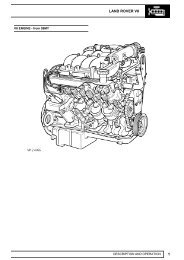
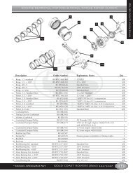
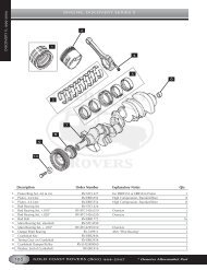
ENGINE – TD6The crankshaft is manufactured from high tensile steel. The bearing surfaces <strong>and</strong> radii are inductively hardened fortoughness <strong>and</strong> fatigue resistance. It is supported on 7 main bearings with a flanged thrust bearing located betweenNo 5 <strong>and</strong> No 6 cylinders. Dynamic balancing is achieved by the use of twelve balance weights.Cross-drillings in the crankshaft between the adjoining main <strong>and</strong> big-end bearings are used to divert the lubricationoil to the big-end bearings.Crankshafts are available in three sizes:l St<strong>and</strong>ardl Undersize 1l Undersize 2.Colour coding identifies the size of the journal.NOTE: For information on colour coding <strong>and</strong> journal sizes, refer to the General Data section of the workshop manual.At the front of the crankshaft is a four-hole threaded connection, used to attach the axially vibration damper <strong>and</strong>cooling fan. The engine RPM signal is taken from the reluctor “target” attached to the crankshaft.The crankshaft oil seals are manufactured from PTFE.Main BearingsThe main crankshaft bearing shells have oil grooves <strong>and</strong> a drilling in the upper bearing shell, to provide oil via thecrankshaft drillings to the connecting rod big-end bearings.SumpThe one-piece aluminium die-cast sump, with an integral tunnel for the differential drive shaft, is sealed to the lowercrankcase extension using a rubber metal-backed gasket. The sump is fixed to the lower crankcase extension using25 bolts. An oil deflector plate is attached to the crankcase reinforcing shell above the sump.Oil PumpThe oil pump assembly is bolted to the bottom of the cylinder block <strong>and</strong> is located in front of the engine block stiffenerplate. The pump is an internal gear-type with sintered rotors <strong>and</strong> is driven through a chain <strong>and</strong> sprocket system fromthe crankshaft.A pressure relief valve is included at the outlet side of the oil pump to control oil pressure at high engine speeds byrecirculating oil through the relief valve back around the pump to the inlet. The relief valve <strong>and</strong> spring is a plunger type;when oil pressure is great enough to lift the plunger, oil is allowed to escape past the plunger to relieve pressure <strong>and</strong>prevent any further rise in pressure.Oil is delivered to the pump from the pick-up pipe, <strong>and</strong> the outlet side of the oil pump delivers pressurised oil flow tothe engine block main oil delivery gallery.FlywheelLocated between the engine <strong>and</strong> transmission the flywheel is of sheet metal laminated construction.12-1-6 DESCRIPTION AND OPERATION