
Create successful ePaper yourself
Turn your PDF publications into a flip-book with our unique Google optimized e-Paper software.
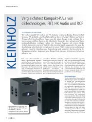
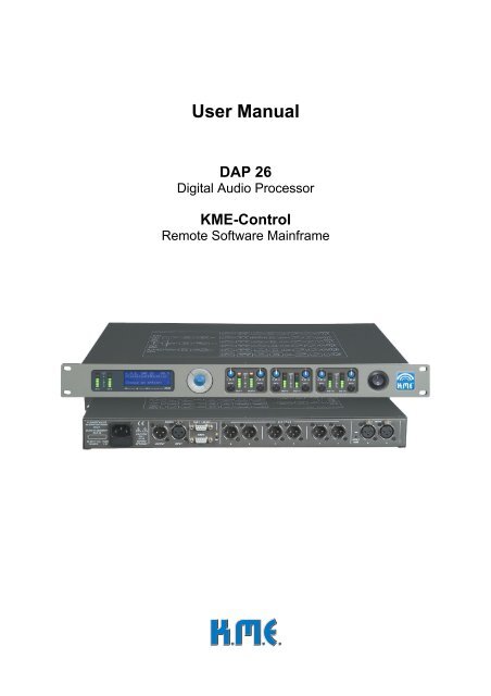
Functional unitsThe <strong>DAP</strong> <strong>26</strong> offers a lot of functional units for general audio processing using apowerful DSP mainframe such as 9 filter banks with each 5 configurable filters of 9different types, 6 crossover units with two combinable filters out of 3 types, 3 masterdelays (up to 2000 ms / 685 meters), 6 channel delays (up to 500 ms / 170 meters)and 6 dynamic processors (compressor / limiter / noise gate).All this functional units can be programmed either directly on the hardware unit or byusing the real-time control software ‚<strong>KME</strong>Control’..Switches and KnobsFront sideCLIP+0dB-60K.M.E. <strong>DAP</strong><strong>26</strong> V0.1Preset ConfigurationChoose an option!-6 dB +6MU TELIMIT LIMIT LIMIT+++000-6 dB +6 -6 dB +6-6 dB +6 -6 dB +6-6 dB +6dBMUTE MUTEdBMUTE MU TEdBMUTE-60-60-60IN AIN BInput level metersTwo 10-digit digital level meters help to set the correct input level on the analog audioinputs or to monitor the digital audio input level.The graphic below shows different peak input levels on your unit:a b c da) too less input levelb) input level OKc) maximum input leveld) too much input level – clipping may occurThe analog input circuit contains a limiter unit for preventing the A/D- converters fromclipping. Nevertheless the analog input level must not exceed the red LED of theinput level meter to prevent reproduction of a distorted signal. Set the source levelthat only the yellow LEDs light up in peaks.
DisplayK.M.E. <strong>DAP</strong><strong>26</strong> V0.1Preset ConfigurationChoose an option!A 4x20 back-lighted LCD display shows the navigation menu. You can set allsoftware parameters on the unit itself. Arrows in the lower right corner show thedirections to navigate to submenus. (see appendix ‘navigation structure’). Use thenavigation pad to move between the menus. Press the ‘OK’ button to select aparameter if you are asked by the unit.Navigation PadThe navigation pad is to be used for accessing and changing parameters on thedisplay of the hardware unit. Press the OK button if you are asked by the software.See also the appendix ‘menu structure’!Level meter 1-6Level correction 1-6Mute switch 1-6-6 dB +6MUTELIMIT+0dB-60-6 dB +6MUTEThe level correction pot adjusts the output level of the corresponding channel by +/- 6dB. This is done on digital signal level and independent from the gain correction inthe software plug-in.Pressing the mute switch mutes the corresponding output channel. The level meterstill displays the output level to avoid unintentional triggering of the switches.
There is a 10-digit LED bar-graph for each output channel which displays thefollowing information:a b ca) there is an output signal on channel X (if the mute switch is not activated)b) the signal on output X exceeds the maximum output level (if the mute switch isnot activated)c) there is an output signal on channel X, the dynamic processor (Compressor/Limiter) is activated and worksMains switchUse this switch for powering up the hardware unit. We included a power-up delaywhich prevents clicks or plops in the speakers efficiently, nevertheless werecommend switching on your power amplifiers after the <strong>DAP</strong>.The backlighting of the display shows that the <strong>DAP</strong> is switched on and the mainspower is within the useable range. If the display does not light check your mainsvoltage and / or the mains fuse which is located in the mains connector.
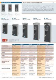
ConnectorsRear sideKLINGENTHALERMUSIKELEKTRONIKGmbHMADE IN GERMANY<strong>DAP</strong> <strong>26</strong>85-<strong>26</strong>4V~AC; FUSE50-60Hz 1 ATCAUTION!PULLPLUGBEFOREOPENING!CAN 1 / RS 232DIGITAL OUTPUT INPUTCAN 2INPUT+6dBOUTPUTINPUT 6 4 2 B5 3 1 AThere are all connectors located on the rear side of the unit.Analog inputs / level select switchINPUTINPUT+6dBBAThe audio inputs of the <strong>DAP</strong> <strong>26</strong> are electronically balanced. Unless it is necessary wedo not recommend unbalanced audio connections. The inputs have to be operatedwith an nominal audio level of either 775 mV (0 dB) or 1.55V (+6 dB) which you canselect using the switch beside the connector “b” corresponding to the signal levelyour source units work with.33211 2XLR-to- XLR balanced audio connection321Jack-to-XLR balanced audio connectionUse one of this cables for connecting the analog audio inputs of the <strong>DAP</strong> <strong>26</strong> to yourmixer / stagebox or to another signal source.
This cable can be used connecting the <strong>DAP</strong> <strong>26</strong> to the CAN port interface box, usingyour multicore system (i.e. XLR). Use such cable also for linking the CAN bus fromunit to unit. Do not forget connecting the CAN terminator plug to the free connectionport of the last unit, otherwise the CAN transmission could be disturbed.5 4 3 21129 8 7 631 231 2 3 4 56 7 8 9Digital Audio InputDigital Audio OutputDIGITALOUTPUTINPUTThe digital input accepts digital audio signals according to AES/EBU with a bit rate of16 to 24 and a sampling frequency of 32 to 96 kHz using an internal format-/samplerate converter chip. The digital audio output loops the selected input (analog/digital)as a 24-bit/96 kHz AES/EBU signal for cascading additional units or recording thesignal to a studio digital recorder. All digital connections are transformer- balanced formaximum protection against ground loops.33211 2Digital Audio Connection Cable (AES/ EBU) w. 110 OhmsWe do not recommend using “normal microphone cable” for AES/EBU connectionsalso when it ‘seems’ to work. Only specified 110 Ohms digital audio cable will give aproper connection without data loss and digital drop-outs.
Switching the inputs to ‚digital’:K.M.E. <strong>DAP</strong><strong>26</strong>Preset ConfigurationChoose an option! >ˆK.M.E. <strong>DAP</strong><strong>26</strong>PresetinfoChoose an option!‹ ›K.M.E. <strong>DAP</strong><strong>26</strong>DevicesettingChoose an option!‹ ›ˆ ˆ ˆDevicesettingsIn-select: AnalogOK: Change Value ˆ>DevicesettingsIn-select: DigitalOK: Change Value ˆ>DevicesettingsIn-select: DigitalOK: Change Value ˆ>Follow this navigation scheme for selecting the digital audio input of the <strong>DAP</strong> <strong>26</strong>. Thisis one of the few actions that can only be used on the hardware unit itself!Mains power connector / fuseKLINGENTHALERMUSIKELEKTRONIKGmbHMADE IN GERMANY<strong>DAP</strong> <strong>26</strong>85-<strong>26</strong>4V~AC; FUSE50-60Hz 1 ATCAUTION!PULLPLUGBEFOREOPENING!Connect the supplied mains power cable to this socket. If the supplied cable is notconform to your local mains allocation, use another cable which fits to the necessaryspecification or ask a technician to change the mains plug. The <strong>DAP</strong> <strong>26</strong> works with alltypes of mains power between 100 and 250 volts without pre-selection.If the fuse breaks, replace it by using an 1 amp slow-blow fuse of the 5x20 shape. DoNOT use fuses different to that type and do NOT try things like ‘patching’ the brokenfuse with aluminium foil etc. because this may lead to risk of fire or electric shock!If the new fuse burns out again then there might be a damage inside the unit! Thereare no user-serviceable parts inside the <strong>DAP</strong> <strong>26</strong>! Contact the K.M.E. support in thiscase!
HandlingFunctional units (digital)All of this functional units are to be set directly in the hardware unit or using theK.M.E. Control software. The names refer to the MENU PROMPT.Input ChannelsDSP- functions in the input channelsDelayChannel [1 … 3]Value [0 – 2.000 ms]Time-delay in the input and all output channels routed to this input channel(Master – Delay).MuteChannel [1 … 3]Value [Mute Off … Mute On]Mute in the input and all output channels routed to this input channel (Master –Mute).GainChannel [1 … 3]Value [-60 dB ... +10 dB]Gain in the input and all output channels routed to this input channel (Master –Gain). The output level pots are to be used independently!FiltersChannel [1 … 3]Filter [1 ... 5]Type[Filter type – see chapter ‚Filters’]Frequency [20 Hz ... 44 kHz]Q (bandwidth) [0,1 … 20]Gain (boost/cut) [-20 dB … +12 dB]Equalizer of the Input and all output channels routed to this input (Master –EQ). This EQ can be used as ‘main’ equalizer for the PA system . Moreinformation to the filters is given in the chapter ‚Filters’!Output ChannelsDSP- functions in the output channelsDelayChannel [1 … 6]Value [0 - 500 ms]Time-delay in the outputMuteChannel [1 … 6]Value [Mute Off … Mute On]
Mute of the outputGainChannel [1 … 6]Value [-60 dB ... +10 dB]Gain level of the outputPhaseChannel [1 … 6]Phase [0° (In Phase) … 180° (Out of Phase)]Polarity of the outputFilterChannel [1 … 6]Filter [1 ... 5]Type[Filter type – see chapter ‚Filters’]Frequency [20 Hz ... 44 kHz]Q (bandwidth) [0,1 … 20]Gain (boost/cut) [-20 dB … +12 dB]Equalizer of the Output which can be used for correction of different speakeroutput ways. More information to the filters is given in the chapter ‚Filters’!XoverChannel [1 … 6]LP-Type [Bypass; Butterworth; Linkwitz- Riley; Bessel]LP-Freq [20 Hz ... 44 kHz]LP-Order [1 ... 8] (filter-depending)HP-Type [Bypass; Butterworth; Linkwitz- Riley; Bessel]HP-Freq [20 Hz ... 44 kHz]HP-Order [1 ... 8] (filter-depending)Frequency crossover networks for the different output channels. Using a singlefilter (low-pass or high-pass) or a valid combination of both filter banks (bandpass)a powerful tool for controlling PA systems is given to the user.The user can select a filter of the types Butterworth / Bessel and Linkwitz /Riley. For users without profound knowledge of filter theory we recommendusing the Linkwitz- Riley filter algorithm for most applications.DynamicChannel [1 … 6]Type [Bypass; Limiter; Compressor]Gain [-10 dB … +10 dB]Threshold [-40 dB … +10 dB]Knee [0 dB …10 dB]Ratio [1:1 … 10:1] (nur Compressor)Attack [0,1 ms … , 1000 ms]Release [1 ms … 10000 ms]Dynamic processor of the output.
Depending to the setting of the parameters a dynamic processing of the inputmaterial will occur when the audio signal level exceeds the adjusted thresholdvalue. The gain reduction works corresponding to the selected algorithm(compressor or limiter). The limiter works with a ratio of infinite:1 what meansthat the input level may be theoretically be increased by any value without achange in the output level which can be specified using the threshold and gainslider.The knee value describes the shape of the regulation curve. A knee value of 0means a hard compression / limiting (the processing starts immediately afterexceeding the threshold level), a higher knee value describes a curve which ismore soft and sounds normally better depending on the program material.The attack/release time draw the speed of the gain regulation mechanism. Alonger attack time will let some signal peaks pass which may sound morepowerful, a short attack time will give more protection to the speakers.A longer release time is advantageous for maximum protection of speakercomponents, on the other hand a short release time increases the averagesound level (using the compressor algorithm).NoisegateChannel [1 … 6]Type [Bypass; Gate On]Threshold [-85 dB … -35 dB]Close [1 ms … 1000 ms]Hold [1ms … 10000 ms]Noise gate of the output. Due to the setting of threshold level the noise gatecan be used for gating disturbing background noise or even audio sources oflow level. Just set the threshold to the level you want to gate – set a hold time(the processor “waits” this time before fading out the audio signal) and a closetime (length of the fade-out itself). When the audio level is above the thresholdagain, it is faded in quickly and automatically!
Filter featuresThe DSP of the <strong>DAP</strong> <strong>26</strong> comes with many different filter types which are combinableas desired. In the following you can find some short information about the filters andtheir usage.Context between bandwidth and the „Q“ factorBandwidth Q comment Q Bandwidth comment(octaves) factor factor (octaves)0,5 2,9 Narrow 0,4 3,0 wide1,0 1,4 ... 1,4 1,0 ...1,5 0,9 ... 2,4 0,6 ...2,0 0,7 wide 4,4 0,3 narrowParametric filtersThe so called ‚parametric’ filters are widely used in professional audio equipment, forexample in mixing desks or speaker processors. The curve of this filter is describedwith certain parameters, mainly the centre frequency, the bandwidth and the gain(boost/cut) of the filter. Combinations of these parameters can control the frequencyresponse of an acoustical system.
PEQ IParametric Equalizer Type IFull-parametric equalizer with different bandwidth for boost (normal) and cut (morenarrow) to create more subtle changes in the audio material. We recommend usingthis filter for ‘standard’ audio requirements.Centre frequency 20 Hz - 44 kHzBoost/cut + 12 dB - - 20 dBbandwidth „Q“ 0,1 - 20It is recommended to set the value for „Q“ between 0.4 (wide) – 1.4 (normal) – 4.0(narrow). Higher / lower “Q” values are not recommended unless the user hasenough knowledge using this special filters.PEQ IIParametric Equalizer Type IIFull-parametric equalizer like the types known from mixing desks.Centre frequency 20 Hz - 44 kHzBoost/cut + 12 dB - - 20 dBbandwidth „Q“ 0,1 - 20It is recommended to set the value for „Q“ between 0.4 (wide) – 1.4 (normal) – 4.0(narrow). Higher / lower “Q” values are not recommended unless the user hasenough knowledge using this special filters.
Shelv- filterA shelv filter can be found in nearly every mixing desk, normally for low and highfrequency adjustment. They can boost or cut a wide frequency range above (highshelv) or below (low shelf) the mid- frequency. Furthermore we added shelv filterswith adjustable bandwidth (LSQ and HSQ) which are, corresponding to the value ofthe „Q“ facto (we recommend values between 0,4 and 4,0), either more “flat” than“normal” shelvs (Q=0.7) or with a higher “Q” (1.0 to 4.0) they create an useful “peak”around the mid frequency.Setting the bandwidth outside of Q 4,0 is not recommended.LS 6dBLo- Shelv- Filter 6 dBmid frequency 20 Hz - 44 kHzBoost/cut + 12 dB - - 20 dBLSQ 12dBLo- Shelv- Filter 12 dB with adjustable “Q” factormid frequency 20 Hz - 44 kHzBoost/cut + 12 dB - - 20 dBbandwidth „Q“ 0,1 - 20At Q= 0,7 you have a „normal“12dB- Shelv- Filter.Setting the bandwidth outside of Q 4,0 is not recommended.HS 6dBHi- Shelv- Filter 6 dBmid frequency 20 Hz - 44 kHzBoost/cut + 12 dB - - 20 dBHSQ 12dBHi- Shelv- Filter 12 dB with adjustable “Q” factormid frequency 20 Hz - 44 kHzBoost/cut + 12 dB - - 20 dBbandwidth „Q“ 0,1 - 20At Q= 0,7 you have a „normal“12dB- Shelv- Filter.Setting the bandwidth outside of Q 4,0 is not recommended.
High-pass and Low-passTo restrict the frequency response of an acoustic system in the low or the high end,the high pass (which actually means “low-cut”) and the low pass filter is implemented.LPLowpass Filter 12 dB with adjustable “Q” factormid frequency 20 Hz - 44 kHzbandwidth „Q“ 0,1 - 20At Q= 0,7 you have a „normal“ low pass filter like you find it in some professionalmixing consoles (High-Cut).Setting the bandwidth outside of Q 2,0 is not recommended.HPHigh Pass Filter 12 dB with adjustable “Q” factormid frequency 20 Hz - 44 kHzbandwidth „Q“ 0,1 - 20At Q= 0,7 you have a „normal“ low pass filter like you find it in some professionalmixing consoles (Lo-Cut).Setting the bandwidth outside of Q 2,0 is not recommended.BPBandpass- Filter with adjustable “Q” factorThe band-pass filter is rarely used in professional audio technology. The band-passfilter lets, in opposite to the notch filter, pass a audio band defined by the midfrequency and bandwidth.
mid frequency 20 Hz - 44 kHzbandwidth „Q“ 0,1 - 20BSNotch FilterThe notch filter filters out a frequency range defined by the mid frequency and thebandwidth. With a “Q” factor above 5 this filter is very narrow, allowing the user tofilter out unwanted frequencies (i.e. mains hum at 50 Hz and certain harmonics)completely. With a “Q” factor below 5 the filter response is quite wide but this set-upis seldom used in professional audio systems.mid frequency 20 Hz - 44 kHzbandwidth „Q“ 0,1 - 20
All-pass filters do not change the frequency response of an acoustoelectric system atall but the phase response. They can be used to influence the phase response. Thisis a complex field in filter theory and so all-pass filters should only be used byengineers who have ‘enough’ theoretical background. Incorrect all-pass filtering maynot damage the sound system but affect the sound in a negative way.The mode of action is presented here:AP IAll-pass filter Type IThis filter creates a quite flat, smooth phase shift over the whole frequency range witha characteristic 90° pole at the centre frequency.mid frequency 20 Hz - 44 kHzAP IIAll-pass filter Type IIThis filter creates a steep phase shift at the centre frequency. The course of thephase curve may be affected by the „Q“ factor.mid frequency 20 Hz - 44 kHzbandwidth „Q“ 0,1 - 20
The software - <strong>KME</strong> Control<strong>KME</strong> Control is a flexible software mainframe to be completed with different plug-inswhich can control different K.M.E. products. At present there are plug-ins for the <strong>DAP</strong><strong>26</strong> and the RCM Network Remote Control Module available.InstallationStart the program ‘<strong>KME</strong>-Setup.exe’ which you have received together with the <strong>DAP</strong><strong>26</strong> (Installation CD) or from the Internet download.Select the installation language (German/English) and press ‘OK’!Follow the installation assistant – click ‚Continue>’.Please accept the licence agreement and click ‚Continue>’.
Select an installation folder in your system hard disc. We recommend using the foldersuggested by the installation assistant. Click ‘Continue>’.Select the modules you want to install within the mainframe. The modules may varywith different software releases. To work with the <strong>DAP</strong> <strong>26</strong> you must install the <strong>DAP</strong>plug-in. You cannot deselect the installation of the mainframe <strong>KME</strong> Control.Select the entry in your ‚Start’ Menu. We recommend accepting ‚<strong>KME</strong>’. Click‘Continue>’.Select if you want to create a Quick Launch icon or an icon on your desktop.
In this window you can check all installation details before you proceed. If everythingis set up right, click the ‘Installation’ Button to start the software installation on yourcomputer.After the installation has finished successfully, this window is shown. You can selectif you want to start <strong>KME</strong> Control now by clicking the ‘Finish’ Button. You can alsodeselect the checkbox if you want to start <strong>KME</strong> Control later.
Installation Problems:• Program cannot be installed, following window appears:De-install an older version of <strong>KME</strong> Control first. Select ‘Start’ ‘Programs’ ‚<strong>KME</strong>’ (oryour installation folder) ‚Remove <strong>KME</strong> Control’ and follow the de-installationassistant.Close <strong>KME</strong> Control first before trying to install a new plug-in or update. We alsorecommend closing all other programs during an installation process of new software.If you receive this message you can select ‚Yes’ without caring about your userpresets stored in this folder to be deleted. They will not be deleted, even by deinstallationof the software. To erase the software completely from your computer,this folder has to be deleted manually using the Explorer window. All of your userdata will be lost.
Software operationStart <strong>KME</strong>Control.On the mainframe window you find the installed plug-ins in a bar below the mainmenus. In this example the plug-ins <strong>DAP</strong> <strong>26</strong> and RCM are installed.Clicking on the <strong>DAP</strong> <strong>26</strong> symbol the plug-in will be loaded into the mainframe window.The plug-in may be activated more than once, in the actual release you can select upto four active windows (limited to screen capabilities).In RS 232 mode you can connect up to four <strong>DAP</strong> units to your computer (if enoughCOM ports are present).By adding the CAN Bus option the user is able to use up to 63 hardware units on onehost computer. Refer to the CAN Bus part of this manual for additional information.The mainframe window with loaded <strong>DAP</strong> <strong>26</strong> plug-in:
Example: Connecting two <strong>DAP</strong> <strong>26</strong> on different COM ports:
Functions in the main WindowMenu bar:FileOpen PresetOpens a preset from a local drive of your computer. You are being asked if you wantto overwrite the actual (which means the preset inside the active window) preset. Ifyou are not sure that you want to discard your last changes, select ‘No’ and saveyour preset to disc using ‘Save Preset’.If you choose ‚Yes’ the ‚Open’ dialogue window will be opened. Navigate to thelocation of the preset file you want to load and click ‘Open’. The only files to beloaded are *.KPF which means K.M.E. preset file.Select the preset you want to load and click ‚Open’.Save PresetSaves your actual preset to a disc of your computer. You can send this preset file tothe technical support later or archive it for future use.
Select a file name for your preset that shall be saved, and click ‚Save’. Werecommend saving presets to the main <strong>KME</strong> Control installation directory. Duringupgrades and de-installations of <strong>KME</strong> Control this preset files will not be deleted!CloseCloses the active <strong>DAP</strong> <strong>26</strong> plug-in window. A dialogue appears to ask if you want tosave your last changes to the preset.Selecting ‚Yes’ opens the ‚Save’ dialogue, ‚No’ closes the plug-in window and‚Cancel’ returns to the plug-in window without changes.ExitTerminates the <strong>KME</strong> Control mainframe. You will be asked if you really want to exit.Selecting ‚No’ returns to the program, ‚Yes’ terminates the program. If there are dataunsaved you will be asked to save or discard them.If you are not sure that you did save your changes select ‚Yes’ and use the ‚Save’function.
Tools (some tools are only activated in online mode)Copy Channel SetupFollowing example shows the usage of this clever tool:Assuming you have created an input EQ curve and a master delay setting in ChannelA and you want to copy the same settings to channel B – just select ‘Input A’ ‘InputB’, select the modules you want to copy (here: delay and PEQ) and click the ‘Copy’button – ready. Same procedure also works for the outputs.Set Password (only in online mode)The tool ‘Set password’ protects your <strong>DAP</strong> <strong>26</strong> from programming by other persons.This may be useful for a rental system to prevent the customer from changing thesettings and possibly damaging parts of your PA system. Setting a password is quiteeasy: Go online to the connected <strong>DAP</strong> <strong>26</strong> first and then select ‘Set password’. Thefollowing window should appear:Enter a 4-digit (only numbers are accepted) password in the field ‚New password’.Enter the password again into the field ‘Confirm password’ and press ‘OK’. Your <strong>DAP</strong><strong>26</strong> is now password-protected.When trying to connect the <strong>DAP</strong> <strong>26</strong> to the computer again you are asked for thepassword to enter. Without this password you can not change any setting in your<strong>DAP</strong>.Changing or deactivating the password is just as easy: Connect the <strong>DAP</strong> to thecomputer and activate online connection. You are asked for the password. Enter thepassword and select ‘Set password’ in the menu. Enter NO password in the field‘new password’ and click ‘OK’. The password will now be deleted.Enter NO password in the field ‘New password’ and click ‘OK’. The password will nowbe deleted.
Attention!If you forget the password there is NO chance to re-activate the unit unless you sendit in to the K.M.E. support for factory re-initialisation. All user data (presets,…) insidethe unit will be lost afterwards.Firmware UpdateFor future upgrades of your <strong>DAP</strong> <strong>26</strong> you can use the firmware update which renewsthe DSP software inside the unit.The firmware update is easy to do. If you have received a new firmware file with an e-mail from the K.M.E. support or by download from the Internet you can program it toyour hardware using the ‘Firmware update’ procedure from the main menu. If there isa firmware update manual included to the firmware download please read this file firstand follow the manual whilst doing the update procedure.Attention! The unit must be connected using RS 232 COM port. Firmware update isNOT possible by using CAN connection.Click ‚Open File’ and navigate to the location of the new firmware file (*.mhx).Klick ‚Open’ and then ‘Program <strong>DAP</strong>’. Do EXACTLY the action the program is askingyou to do. Transmitting the firmware to the <strong>DAP</strong> may take several minutes.Attention!Do not interrupt the mains power and/or the serial connection between the <strong>DAP</strong> andyour computer during the update process. Avoid running unnecessary programs onyour computer during the update.
After the <strong>DAP</strong> has received the complete new firmware it does the update procedureand the new functions will be ready after powering the unit off and on again.Remote Watch (only available in online mode)The function module ‚remote watch’ shows the front of a remote located <strong>DAP</strong> <strong>26</strong> withits meters and output gain pots in real-time. In this mode the user may controlinput/output levels or compressor/limiter thresholds from the remote location (onlyuseful when connecting the units by CAN Bus for distances up to 400 meters).Quick SetupThe menu ‚Quick setup’ contains pre-prepared configurations for various PAapplications. They include routing and crossover standard settings for all channels.This may save time creating new set-ups. To load a set-up from the list just click onit. You are being asked if you want to overwrite the actual preset.Select ‚No’ if you want to save your actual preset first. Selecting ‘Yes’ loads andinitialises the selected set-up. The different quick set-ups are described in theappendix ‘Quick Setup’.WindowYou find window-based commands like ‘New Window’, ‚Cascade’, ‚Tile’ and ‚ArrangeIcons’ in this menu. Use them to change the style of display on your PC screen.HelpHelp TopicsThis menu opens the help window containing a quick reference to most programfunctions.You can terminate the help window using the ‚Close’ button on the top right corner.
About <strong>DAP</strong> <strong>26</strong>The ‚About’ function shows the version number and revision of the <strong>DAP</strong> <strong>26</strong> plug-in.This information may be required contacting the K.M.E support.Click ’OK’ to close this window or click the blue link to visit the K.M.E. homepage(requires active Internet connection).
Going ’Online’ (using RS 232 as an example)(assuming the communication line RS232 is already connected and working)Set the ‚Connection’ field of the <strong>DAP</strong> <strong>26</strong> plug-in to ‘RS232’ and the ‘Com Port’ field to‘COM1’ (or the COM port your <strong>DAP</strong> <strong>26</strong> is connected to). Click ‘Connect’.If you did set a password in a previous session you will be asked for it..Enter the 4-digit password and click ‚OK’ to start the connection.After entering a wrong password you will get a notice window for two times.You have three trials, after that you need to restart the software and initialisethe communication again. If you forgot the password you will have to sendthe hardware unit to the K.M.E. support for factory re-initialisation.Please refer also to the chapter ‚Set password’ of this manual!If everything is OK with the communication the following window will appear, showingthat data is exchanged between the <strong>DAP</strong> <strong>26</strong> and your PC.If the connection is set-up, you are being asked if you want to copy the actual preset(which you probably just made in your PC) to the <strong>DAP</strong> <strong>26</strong>. Click ‘Yes’ if you want todo so.If you select ‚No’ you can load a preset from the <strong>DAP</strong> <strong>26</strong> to make changes. Beforeany data is loaded from the hardware unit to your PC you are being asked if you wantto save your actual work.
Selecting ‚Yes’ opens the ‚Save’ dialogue, selecting ‚No’ starts the transmission ofthe presets from the <strong>DAP</strong> <strong>26</strong> to the PC. You can select the number of the preset tochange.While you are in online mode you cannot change any settings in the <strong>DAP</strong> <strong>26</strong> byhardware. The unit is locked, the display shows:UNIT LOCKED due toPC CONNECTIONDISCONNECT from PCor RESTART to unlockTo make settings on the hardware unit you have to go ‘Offline’ pressing the‘Disconnect’ button.Clicking into the ‚Preset’ list box allows the user to load another preset into thesoftware plug-in by selecting one out of the list.The selected preset will be loaded.When you have made your changes to the preset you can save the preset in thehardware unit by clicking the ‚store preset’ button. The software sends the presetback to the <strong>DAP</strong> <strong>26</strong> and stores it in the internal memory.When there is a communication problem between the <strong>DAP</strong> <strong>26</strong> and your PC thefollowing window will be displayed:
There might be one (or more) of the following problems:• the <strong>DAP</strong> <strong>26</strong> is switched offSolution: switch ’on’ the <strong>DAP</strong> you want to communicate with• the <strong>DAP</strong> <strong>26</strong> is not connected to the selected COM portSolution: check the connection between the <strong>DAP</strong> <strong>26</strong> and your computer. Didyou use the correct COM port? Is there any software to be installed using aUSBtoRS232 converter on systems without ‘native’ COM ports (refer to themanual of the specific converter).• COM port is used by another applicationSolution: Some programs, especially serial MIDI device drivers block COMports. If possible deactivate all programs you do not need at the time you wantto use your computer programming a <strong>DAP</strong> <strong>26</strong>. Try using another COM port oruse a USBtoRS232 converter connected to the USB port of your computer.• You are using the wrong cableSolution: Do only use cables according to the K.M.E. specification to avoidcommunication errors or even damages of both the <strong>DAP</strong> <strong>26</strong> or your computer.• You are using the wrong communication port on the <strong>DAP</strong> <strong>26</strong>Solution: Only use the upper connector labelled ‚RS232/CAN’ for serialcommunication with a PC COM port. Make sure that nothing is connected to thelower port in RS232 mode!• The <strong>DAP</strong> <strong>26</strong> is not in RS 232 mode (LED does not light)Solution: Operate the switch beside the connectors to activate RS 232 mode.The yellow LED must light up if you want to use RS 232 communication.• There is another problem...Solution: Contact the K.M.E. support.
Signal FlowThe register tabs can be accessed out of all functional modules. The tab ‘Signal flow’includes the routing matrix and the activation of all other audio modules by clicking.MagnitudeThe tab ‚Magnitude’ is active within the modules ‘Equalizer’ and ‘Crossover’ andshows the frequency response of the selected channel affected by crossovernetworks and / or filters. This tab includes drag-and-drop functionality with themouse.PhaseThe tab ‚Phase’ is active within the modules Equalizer and Crossover and shows thephase response of the selected channel affected by crossover networks and/or filters.Drag-and-drop is deactivated on the ‘Phase’ tab.DynamicThe register tab ‚Dynamic’ is activated in the dynamic processor module only. Itshows the characteristic of the selected compressor/limiter function.
Functional unitsIn/OutIn this window the user can rename the input and output lines of the processor orname the actual preset and add information about author/date. The values are storedin the hardware unit and can be read out by other users.GainIn this window the input / output levels can be either set by mouse, writing thespecified gain value in the ‘dB’ field or using the cursor keys for fine adjustment of thepre-selected fader. You can operate the ‘Mute’ buttons, ‘Polarity’ switches and‘Stereo link’ / ‘Mute all’ buttons as desired.Delay
In this window you can set the time delays for all channels. This can either be doneby clicking the up/down arrows behind the fields or entering the delay values into thefields. As delay units you can select µs, ms, s, cm, m and feet. While the soundvelocity is depending on temperature, this field corresponds to the delay units cm, mand feet.EqualizerIn this window you find 9 register cards where you can make the EQ settings for thecorresponding channel. For each channel you may combine any 5 filters of theavailable filter types. The filter types are described in the chapter ‘filters’. To activatea filter, first select the channel in which you want to add the filter by selecting aregister card. Then activate one of the 5 filters by clicking into the grey ‘Bypass’ fieldbelow the red field labelled ‘Filter X’. This field will change to green to signalise thefilter is working.Select in the field ‘Filter type’ the filter algorithm you want to use and adjust thevalues for ‚Freq.’, ‚Gain’ and. ‚Q’.Select the register card ‚Magnitude’ to view the influence of the activated filters to thefrequency response of the selected channel.
The coloured triangles are named with the specific filter number. It is possible tomove this points with the mouse and monitor the acoustic changes in real-time afterreleasing the mouse button when the <strong>DAP</strong><strong>26</strong> is online.Here is an example how to create a “classic”, mixing desk- type equalizer using thefilter banks of the <strong>DAP</strong> <strong>26</strong>:
Filters 1-4 are to be set to the values specified below. The remaining filter could beused as a Low- Cut i.e. at 80 Hz.
XOVERIn this window you find 6 register cards for setting up the crossover functions of theoutput channels. Each filter bank consists of a ‘LowCut’ and a ‘HighCut’ type filterwhich can be activated and programmed to your needs.The set-up of the crossover section shall be described using an easy example:Assuming that you want to set output channels 1&2 for the bass and 3&4 for themid/high systems.Prior to the crossover adjustment you already set the correct signal flow in the routingmatrix (see below).To assign an output to a “bass” channel simply activate the ‚High Cut’ Filter byclicking into the grey ‚Bypass’ button below the red control field labelled ‘High Cut’.This field will change to green when the filter is activated.We recommend using the filter type ‘Linkwitz- Riley’ for any standard crossoverapplications. For this example set the filter frequency to 120 Hz. This can be done byentering ‘120’ into the ‘Freq.’ field or by using the mouse in the graphical ‘Magnitude’display clicking on a curve and dragging it to the correct position. This operates inreal-time when the <strong>DAP</strong> <strong>26</strong> is online.This example would look in the software like this:
As you can see the output channel 1 contains only the bass frequencies below120Hz.The settings may be copied to channel 2 using the ‚Copy Parameter’ dialogue orsetting it manually.To operate channels 3&4 as Mid/High outputs proceed as described above but usethe ‘Low Cut’ Filter instead using the same parameters.This setting would look like this:As you can see the output channel 1 contains only the bass frequencies below120Hz.
The settings may be copied to channel 4 using the ‚Copy Parameter’ dialogue orsetting it manually. The same result you may obtain much easier by using the ‘Quick Setup’ dialogue(here: ‘2 Way Stereo’)!Attention!For inexperienced users we do not recommend „experimenting“ around with thecrossover section when you are online with the <strong>DAP</strong> <strong>26</strong> and a sound system isconnected and running. In this case all settings are transmitted to the <strong>DAP</strong> in realtimeand a ‘wrong’ filter may damage the speakers.DynamikIn this window you can activate the dynamic processing units of all output channels.To activate a dynamic processor simply select the register card of the channel youwant to process and click the grey ‘Bypass’ button. The red fields will change togreen when the processor is activated.
The ‚Dynamic’ Window displays the response of the selected dynamic processor andincludes a simple but informative level calculator.In the following some set-ups together with the corresponding curves are shown:a) CompressorThe compressor behaves linear up to the adjusted ‚Threshold’ value. If this value isreached the compressor begins to control the level according to the compressing‘Ratio’ selected. If the ratio is i.e. 4:1 then the level has to increase by 4 dB to allowthe output increasing by 1 dB. This is the ‘compression’ mentioned. With higher ratiosettings, the compression will be more ‘audible’ (which must not be negative at all).The ‘Knee’ value describes the point where the compression starts. A knee value of 0starts the compression exactly at the threshold level. A higher knee value allows tostart compression more softly, normally less audible.
) LimiterA limiter describes a compressor with a compression ratio of 1:infinite what doesmean that no level above the threshold is allowed to pass. Limiters are used formaximum protection of speaker components or maybe for securing maximum soundpressure levels prescribed by law. The ‘Knee’ value is comparable with thecompressor too. Higher knee values allow to start limiting more softly, normally lessaudible.
Attack TimeRelease TimeThis time-constants show the speed of the regulation process inside the compressor /limiter algorithms. A longer ‘Attack’ time will let some peaks pass beforecompression / limiting occurs which may increase the average SPL level while ashort attack time will give more overload protection to the components. The ‘Releasetime’ should be adjusted to the program material used.Speaker and Amp ParameterIn this window you find a level / power calculator.The values entered in this window do not affect the outputs at all but give usefulinformation about the correct threshold level in the dynamic section together with theoutput level of the selected channel.c) NoisegateThe noise gate can be activated by clicking into the grey ‚Bypass’ field. The thresholdslider will occur and the control field will change the colour to green when the noisegate is activated. The operation is easy – just set the threshold level (the minimumsound level above i.e. disturbing background noise). All audio material with a levelbelow the threshold value will be faded out to silence, audio material above thethreshold will not be processed.The parameters ‚Hold Time’ und ‚Close Time’ affect the regulation process. ‘HoldTime’ describes the time the unit „waits“ before fading out signals below the thresholdlevel and the ‚Close time’ describes the speed of the fade-out. Set this constants totaste depending to the program material transmitted.
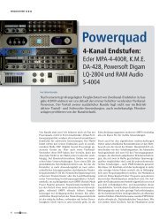
ˆˆˆˆAppendix – navigation structure on the hardware unitK.M.E. <strong>DAP</strong><strong>26</strong>Preset ConfigurationChoose an option! >PresetselectionPreset: XXActive Preset Preset: XXInputchannelsChoose an option! ¦>PrXX/InputsDelayChoose an option! ¦>PrXX/In/DelayChannel AChoose a Channel ¦>PrXX/In/Del/Ch AValue : 0.00msOK: change value! ˆK.M.E. <strong>DAP</strong><strong>26</strong>PresetinfoK.M.E. <strong>DAP</strong><strong>26</strong>DevicesettingK.M.E. <strong>DAP</strong><strong>26</strong>DeviceinfoChoose an option!‹ ›Choose an option!‹ ›Choose an option!‹DevicesettingsIn-select: AnalogDevicesettingsNet-ID : 1Deviceinfo: S/N123456Deviceinfo: RevisionX.XOK: Change Value ˆ> OK: Change Value Choose an Info Choose an Info ˆ>Presetinfo: AuthorChoose an Info Presetinfo: Pr.-LockDisabledChoose an Info Presetinfo: Ch-NamesInput A: < IN-A>Input B: < IN-B>Choose an Info Presetinfo: Ch-NamesOutput 1: < OUT-1>Output 2: < OUT-2>Choose an Info Presetinfo: Ch-NamesOutput 3: < OUT-3>Output 4: < OUT-4>Choose an Info Presetinfo: Ch-NamesOutput 5: < OUT-5>Output 6: < OUT-6>Choose an Info Choose an option! Choose an option! Choose an option!PrXX/Route/Ch1 PrXX/Out/Delay . PrXX/Out/MutePrXX/Out/Gain. PrXX/Out/Phase .Input AChannel 1.. Channel 1Channel 1.. Channel 1..OK: Change Input ˆChoose a Channel ¦> Choose a channel ¦> Choose a Channel ¦> Choose a channel ¦>PrXX/InputsPrXX/InputsPrXX/InputsPrXX/Out/Del/Ch 1PrXX/Out/Mute/Ch 1 PrXX/Out/Gain/Ch 1 PrXX/OutputMuteGainFilterValue : 0.00ms Value : Mute OFF Value : 0.0 dB Phase : 0 °Choose an option! Choose an option! Choose an option!Choose a Channel ¦>Choose a Channel ¦>PrXX/In/Mute/Ch AValue : Mute OFFPrXX/In/Gain/Ch AValue : -0.0dBPrXX/In/Fil/ChAFilterNr. 1OK: change value! ˆOK: change value! ˆChoose a Filter ¦>PrXX/In/Fil/ChATyp : BypassPrXX/In/Fil/ChAFrequency: 1000HzPrXX/In/Fil/ChAQ : 0.7PrXX/In/Fil/ChAGain : 0.0dBOK: Change value ˆ> OK: Change value OK: Change value OK: Change value ...OK: Change value ˆ> OK: Change value PrXX/Out/FilterChannel 1PrXX/Out/X-overChannel 1PrXX/Out/Dyn/Ch1Typ : LimiterPrXX/Out/Dyn/Ch1Gain : 0.0dBPrXX/Out/Dyn/Ch1Threshold: -6.0dBChoose a channel ¦> Choose a channel ¦> OK: Change value ˆ> OK: Change value OK: Change value PrXX/Out/Fil/Ch1FilterNr. 1PrXX/Out/X-over/Ch1LP-Typ : BypassPrXX/Out/X-over/Ch1LP-Freq. : 1000 HzPrXX/Out/X-over/Ch1LP-Order : 4PrXX/Out/X-over/Ch1HP-Typ : BypassChoose a Filter ¦> OK: Change Value ˆ> OK: Change Value OK: Change Value OK: Change Value PrXX/Out/Fil/Ch1/Fi1Typ : BypassPrXX/Out/Fil/Ch1/Fi1Frequency: 1000HzPrXX/Out/Fil/Ch1/Fi1Q : 0.7PrXX/Out/Fil/Ch1/Fi1Gain : 0.0 dBOK: Change value ˆ> OK: Change value OK: Change value OK: Change value
Appendix – Technical DataTechnical Data <strong>DAP</strong> <strong>26</strong> / 96Inputs Analog inputs 2 (XLR)Input impedance balanced20 kOhmmax. input voltage12 / 18 dBUOutputs Analog outputs 6 (XLR)Output impedance balanced130 Ohmmax. output voltage12 dBUProcessor DSP 2 x 32 bit floating point, 100 MHz clockMaximum Ground delay0,7 msSampling24 bit / 96 kHzconverters128 x OversamplingDigital inputAES/EBU / SPDIF withFormat-/ Sample rate converterDynamic range Analog Input to Output >108 dB (A)Distortion (THD) < 0,001%Preset Memory <strong>User</strong> presets 32Software for PC mit Windows 2000, XPPC connectionserial (RS 232) 9 pindetails displays 8-digit LED chains for inputs and outputsbacklighted LCD- DisplayknobsNavigation pad, mains switch, Gain potsSpecial featuresRemote control using RS 232 or CAN BusPower Switched mode power supply 90 - 250 Volt / 50 - 60 Hzdimensions (mm) 483 x 44 x 330weight (kg) 5
For your notes:
Klingenthaler Musikelektronik GmbHAuerbacher Straße <strong>26</strong>808248 Klingenthal / Germanyphone +49 (0)37467 - 558-0fax +49 (0)37467 - 558-33www.kme-sound.comservice@kme-sound.comTechnical State February 2005.The content corresponds to the state at printing. Subject to technical alterations. Misprints and errors expected.Feb 2005 / SL