XDT Manual - Pioneer Air Systems Engineering
XDT Manual - Pioneer Air Systems Engineering
XDT Manual - Pioneer Air Systems Engineering

Create successful ePaper yourself
Turn your PDF publications into a flip-book with our unique Google optimized e-Paper software.
;;;;;;;;yyyyyyyy;;;;;;;;yyyyyyyy;;;;;;;;yyyyyyyy;;;;;;;;yyyyyyyy;;;;;;;;yyyyyyyy;;;;;;;;yyyyyyyy
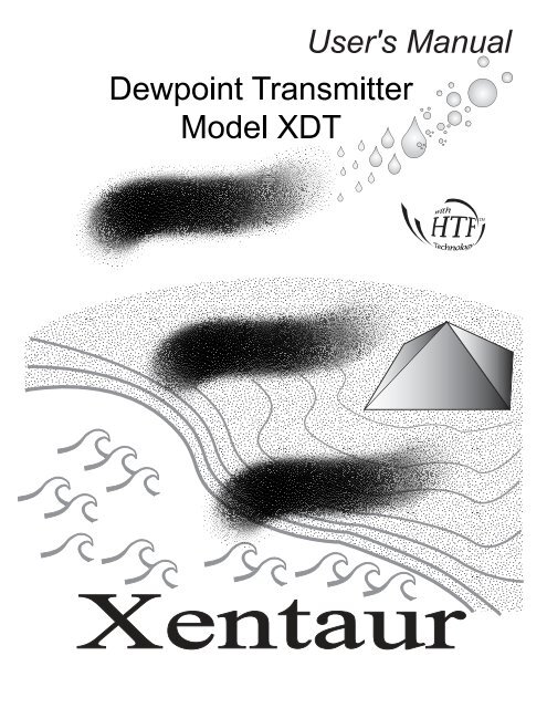
<strong>XDT</strong> User’s <strong>Manual</strong>When calling your representative for technical support, please have your serial numbers available.The Sensor and Instrument Serial Numbers are on the instrument, also see section 3.4.4.4.Sensor Serial No.: _______________Instrument Serial No.: _______________Your Representative is:Except as may be provided by contract, this document and all specificationsand drawings contained are the property of Xentaur Corporation, areissued in strict confidence, and shall not be reproduced or copied or transmitted,in any form or by any means, or used as the basis for the manufactureor sale of apparatus, programs, or services without permission.Check the Internet for updates; the latest revision of this manual is available in Adobe Acrobat formatat: http://www.xentaur.comDocument No.: XDO.01.D.0000 Rev.2.3 5/10/05Copyright © 2000,2004,2005 by Xentaur Corporationi
<strong>XDT</strong> User’s <strong>Manual</strong>Xentaur reserves the right to change or modify the product specification and / or appearance at any timewithout notice. Therefore, the information in this document is subject to change without notice and doesnot represent a commitment on the part of Xentaur Corporation.The customer agrees that in accepting and using this instrument XentaurCorporation’s liability arising from or in any way connectedwith this instrument shall be limited exclusively to performing a newcalibration or replacement or repair of the instrument or sensor, atXentaur’s sole option, as covered by Xentaur’s warranty. In no eventshall Xentaur be liable for any incidental, consequential or specialdamages of any kind or nature whatsoever, including but not limitedto lost profits arising from or in any way connected with this instrumentor items hereunder, whether alleged to arise from breach ofcontract, express or implied warranty, or in tort, including withoutlimitation, negligence, failure to warn or strict liability.Swagelok, Cajon are trademarks of SWAGELOK Co.Acrobat is a trademark of Adobe <strong>Systems</strong> IncorporatedEpson is a registered trademark of Seiko Epson CorporationMicrosoft Windows is a registered trademark of Microsoft CorporationHTF is a trademark of Xentaur CorporationSpanCheck is a trademark of Xentaur CorporationThe Xentaur Logo is a trademark of Xentaur Corporationii
<strong>XDT</strong> User’s <strong>Manual</strong>Examine the <strong>XDT</strong> package for damage or mishandling. If any damage is evidentnotify the carrier and request an inspection.Unpack the box, it should contain: The <strong>XDT</strong>, sensor in desiccant container, connectorizedcable, and this manual.PLEASE READ THIS MANUAL IN WHOLE, PRIOR TO INSTALLING ORREMOVING THE SENSOR FROM ITS SHIPPING CONTAINER.This manual is organized in three sections:Section 1 is an overview of the <strong>XDT</strong>.Section 2 describes the sensor and sampling techniques.Section 3 describes the instrument’s electrical, mechanical, and user interfaces.This manual is intended for those already familiar with the installation, use andmaintenance of analytical or process instrumentation.Those acquainted with other Xentaur dewpoint measurement products such as theLPDT or the XPDM, will benefit from the commonality of the user interface.Warning LabelsThe symbols shown below appear on the instrument to alert the user of potentiallyhazardous conditions.Protective Grounding Conductor TerminalBornier de L’Ecran de ProtectionSchutzerdeCAUTION - Risk of Electric ShockATTENTION - Risque de Décharge ÉlectriqueACHTUNG - Hochspannung LebensgefahrCAUTION - Refer to documentationATTENTION - Se Réferer aux Documents JointsACHTUNG - Beachten Sie beiliegende Dokumenteiii
<strong>XDT</strong> User’s <strong>Manual</strong>WarrantyThis instrument is warranted to be free from defects in workmanship and materials. Liability under thiswarranty is limited to servicing, calibrating, and replacing any defective parts of the instrument returned tothe factory for that purpose. Fuses are specifically excluded from any liability. This warranty is effectivefrom the date of delivery to the original purchaser. The equipment must be determined by Xentaur to havebeen defective for the warranty to be valid. This warranty applies as follows:• one year for electronics• one year for mechanical failures to the sensor• six months for calibrationsIf damage is determined to have been caused by misuse or abnormal conditions of operation, the ownerwill be notified and repairs will be billed at standard rates after approval.Maintenance PolicyIn cases when equipment fault is suspected, please notify your representative of the problem, be sure toprovide them with model and serial numbers. If the problem can not be resolved, then ask for a ReturnAuthorization Number (RAN) and shipping instructions. Issuance of an RAN does not automatically implythat the equipment is covered by our warranty, that will be determined after we receive the equipment.Pack the equipment in a suitable box with sufficient padding, include the RAN number on your paperwork,and send the equipment, prepaid, to the designated address. Equipment returned without an RAN, or withreversed shipping or import/export charges, will not be acceptedIf the warranty has expired, or the damage is due to improper use or exposure of the equipment; then therepair facility will provide an estimate and wait for approval before commencing repairs.For your convenience a Return Authorization Request Form is provided in appendix N, it must be completedand sent back to the provided destination in order to obtain a RAN.iv
<strong>XDT</strong> User’s <strong>Manual</strong>Table of Contents1.0 Overview of the <strong>XDT</strong> ..........................................................................................................12. Sensor and Sampling Techniques ..........................................................................................32.1 Precautions using the sensor ................................................................................................32.2 Sensor Technical Specifications ..........................................................................................42.3 Sensor Installation & Sampling Techniques........................................................................42.3.1 In-situ Installation .............................................................................................................52.3.2 Extractive Installation .......................................................................................................62.4 Mechanical Installation........................................................................................................72.5 Troubleshooting unexpected readings .................................................................................83. Instrument ..............................................................................................................................93.1 Precautions using the <strong>XDT</strong> ..................................................................................................93.1.1 Electromagnetic Compatibility Considerations ................................................................93.2 Instrument Technical Specifications..................................................................................103.3 Installation .........................................................................................................................113.3.1 Instrument Mechanical Installation ................................................................................113.3.1.1 <strong>XDT</strong>-PM (DIN43700) Enclosure Installation .............................................................113.3.1.2 <strong>XDT</strong>-NEMA (IP65) Enclosure Installation.................................................................113.3.1.3 <strong>XDT</strong>-OEM bare board Installation ..............................................................................113.3.2 Electrical Connections ....................................................................................................123.3.2.1 Connecting Power........................................................................................................123.3.2.1.1 AC Mains Electrical Power Connection...................................................................133.3.2.1.2 Low Voltage DC Powered Option - Electrical Power Connection...........................133.3.2.2 Sensor Connection .......................................................................................................133.3.2.3 Wiring the Alarm Contacts ..........................................................................................133.3.2.4 Interfacing to the Analog Output .................................................................................143.3.2.5 Interfacing to the RS-232 option .................................................................................153.4 Operating the Instrument ...................................................................................................153.4.1 Starting up.......................................................................................................................153.4.2 Display Conventions.......................................................................................................163.4.3 Push Buttons ...................................................................................................................163.4.4 Operating State ...............................................................................................................173.4.4.1 Viewing Dewpoint Mode.............................................................................................173.4.4.2 Alarms..........................................................................................................................193.4.4.3 Start Calibration...........................................................................................................203.4.4.3.1 SpanCheck Mode ..................................................................................................213.4.4.3.2 Single Point Self Calibration, manual or scheduled .................................................223.4.4.4 Viewing Serial Number Mode.....................................................................................253.4.5 SetUp State .....................................................................................................................253.5 Resetable Audio-Visual Alarm Option (NFPA compliant)...............................................283.6 Troubleshooting the Instrument.........................................................................................293.7 Maintenance.......................................................................................................................31Glossary ...................................................................................................................................33Appendix A: Flow Diagram of Operating State User Interface ..............................................37Appendix B: Flow Diagram of Set-Up State User Interface ...................................................39v
<strong>XDT</strong> User’s <strong>Manual</strong>Appendix C: Sensor Mechanical .............................................................................................40Appendix D: Optional Sensor Fittings.....................................................................................41Appendix E: <strong>XDT</strong> Circuit Board Dimensions.........................................................................42Appendix F: Sensor/SpanCheck Theory of Operation ........................................................45Appendix G: Dewpoint Response time Analysis ....................................................................46Appendix H: Sample Gas Filter Considerations......................................................................48Appendix I: <strong>XDT</strong> Grounding Considerations..........................................................................49Appendix J: Analog Output vs. Dewpoint...............................................................................50Appendix K: RS-232C Interface Protocol ...............................................................................52Appendix L: Procedure for Exchanging <strong>XDT</strong> Sensors............................................................55Appendix M: Uncertainty in LBS & ppmV calculations ........................................................56Appendix N: Certifications - Approvals - Conformity............................................................57Appendix O: Return Authorization Number Request Form....................................................59Index.........................................................................................................................................61vi
Section 1: Introduction1.0 Overview of the <strong>XDT</strong>The <strong>XDT</strong> is a microprocessor based hygrometer, for measuring moisture content in gases in therange from -100°C to +20°C dewpoint depending on the sensor ordered. The <strong>XDT</strong> uses the XentaurHyper Thin Film HTF sensor which is encapsulated in sintered stainless steel, thus it iscapable of coming into contact with a wide variety of environments. However one should keep inmind that the sensor is a delicate device and it should be handled accordingly.The measurement is displayed on the instrument’s custom LCD, can be transmitted by optionalanalog and digital outputs, and can control optional programmable relays. Four front panel buttonsprovide the user with a rich feature set. The <strong>XDT</strong>’s advanced design allows it to be housed ina variety of enclosures.The <strong>XDT</strong> has an impressive set of dewpoint measurement capabilities in terms of accuracy, stability,response time etc. The specifications of the sensor are discussed in section 2.2, while the specificationsof the instrument are discussed in section 3.2. A summary of the standard and optionalfeatures & capabilities of the <strong>XDT</strong> are listed below as an overview aid to the user.Standard Features/Capabilities• Locking of instrument, preventing unintentional changes• SpanCheck: - automatic recalibration using room air, all instruments pre-calibrated at factory.• Capability to enter up to 15 NIST/NPL traceable calibration points at factory, depending onorder.• <strong>Manual</strong> Self Calibration: a single point calibration using a known standard gas. High accuracycan be maintained even in the most harsh applications.• Pressure correction: built-in software calculation of dewpoint at a pressure different than themeasurement.• Cable length compensation: user initiated automatic self measuring software.• Universal global autoranging AC supply 100-250VAC, 50/60Hz• Instrument and Sensor: UL, cUL, and CSA listed/recognized; CE electromagnetic compatibilitycertifiedOptionally ordered Features/Capabilities• Password protected Locking of instrument, preventing unauthorized changes• Alarm Relays - programmable set points, error handling, and hysteresis. Up to 3 alarm relaysmay be ordered. On-display legends indicate relay states.• Audio Visual Alarm- complies with recommendations of NFPA 99, 1996 edition, audio resetand test buttons.• Analog Output- factory set voltage or user selectable 4/20 - 0/24 mA. Includes installationtesting features. User selectable range (low & high point) of analog output.• RS-232C interface - allowing the user digital data access to the instrument.• Interval-timer-scheduled Self Calibration, a single point calibration using a known standardgas, can operate an electrically actuated switchover valve for unattended calibrations• Large variety of threads for sensor mounting into sample• Low voltage DC power operation 15-30VDC• Intrinsically Safe Approved NEC and ATEX standards (UL & DEMKO) configurations1
<strong>XDT</strong> User’s <strong>Manual</strong>2
Section 2: Sensor and Sampling Techniques2. Sensor and Sampling Techniques2.1 Precautions using the sensorThe Xentaur HTF Al 2 O 3 sensor is designed and field proven to be highly reliable, rugged andmaintenance free. However the user should consider the following precautions:• If the instrument is used to measure moisture in toxic, flammable, or explosive gases, the sampleoutlet must exhaust to a safe place.• Check the sample line for leaks before and after connecting.• If measuring gases at high pressures, make sure the sample system is depressurized beforeinstalling or removing the sensor probe, or other items e.g. filters.• To avoid the need for prolonged dry-down (when expecting to measure dewpoints dryer than–65ºC), do not expose the sensor to room air longer than necessary (1 - 2 minutes). Thus, donot open the sensor container before you are ready to install the sensor.• The sensor container has desiccant to keep the sensor dry during shipping and to avoid damagedue to condensation. Close the container immediately after removing the sensor to avoiddegradation of the desiccant.• Do not throw away the sensor container, you may use it again to transport the sensor betweenlocations, to store it between uses or to ship it back to the factory for certification. The containercan be attached to the sensor cable, by trapping the cable with the lid strap.• Do not expose the sensor to corrosive gases such as gases containing chlorine, ammonia orHCl. (SO 2 can be monitored when the moisture content is low).• Except for the XTR65W sensor:1. Do not expose the sensor to liquid water, as it may get damaged.2. Do not breathe directly onto the sensor, as condensation may form which could damagethe sensor element.• Do not install the sensor near heat sources such as radiators or air ducts.• Do not install the sensor in places subject to extreme mechanical vibration or shock. If this isnot avoidable, use resilient mounting. If in doubt, call your representative.• Do not disassemble the porous metal filter encapsulation, as this will damage the sensor andvoid your factory warranty.• Prior to installation of the probe, ensure that no contaminants are present in the system (e.g.oil, liquid water).3
<strong>XDT</strong> User’s <strong>Manual</strong>2.2 Sensor Technical SpecificationsType: ..................................Hyper Thin Film HTF high capacitance Al 2 O 3 .Dewpoint range:.................XTR-100: -148°F to +68°F (-100°C to +20°C)XTR-65: -85°F to +68°F (-65°C to +20°C).XTR-60: (-60°C to +20°C)XTR-LQ: for use in liquidsCapacitance:.......................15nF to 200nF.Accuracy:...........................±5.5°F (±3°C) refer to appendix M for accuracy expressed in other units of measure.Repeatability:.....................±0.9°F (±0.5°C).Response time:...................refer to Dewpoint Response time analysis in Appendix G.Operating Temperature: .....14°F to 158°F (-10°C to +70°C), non-condensingStorage Temperature: .........-40°F to+176°F (-40°C to +80°C), non-condensingSample Flow range: ...........(linear velocity @ 1ATM): Static to 100m/s.Enclosure: ..........................encapsulated in 100µ sintered stainless steel.Calibration method: ...........Highly uniform sensors calibrated at low dewpoint and SpanCheck, sensor saturates at dewpointabove +68°F (+20°C). NIST/NPL traceable multi-point factory calibration available optionally.Pressure operating range:...Standard:500 PSI (34 bar).Optional:5,000 PSI (340 bar).Mechanical connections:....14mm x 1.25mm sparkplug threads, and ¾”-16 threads, standardOptional configurations: G1/2, 1/2”NPT, 5/8”-18 and othersElectrical connections:.......Female BNC connector.Sensor signal cable: ...........RG58 coaxial cable, or for lengths greater than 100’ RG6 coaxial cable, max 17,000pF.Approvals/Classifications:.CE for electromagnetic compatibility, accredited laboratory tested and certifiedHazardous Locations:UL Class I,II, Division 1, Groups A,B,C,D,E,F,G intrinsically safe when installed per drawings<strong>XDT</strong>.00.D.6001 or <strong>XDT</strong>.00.D.6002 or <strong>XDT</strong>.00.D.6003DEMKO 05 ATEX 0505798X II 1 G EEx ia IIC T6 -20°C≤Ta≤+60°C Intrinsically Safe wheninstalled per drawing <strong>XDT</strong>.00.D.60012.3 Sensor Installation & Sampling TechniquesKeep in mind that the moisture content at the sensor is not only due to the moisture of the gasbeing measured, but also due to desorption of water from tubing, trapped moisture (at the interconnectionpoints, valves, filters and other hygroscopic materials in the system), leaks in the system,and others. Thus the measurement may vary from the expectation, and therefore care shouldbe taken in choosing the sampling technique utilized in the measurement. Factors such as gaspressure, flow rate, materials of construction, length and diameter of tubing, number of interconnectingfittings, dead space in tubing and manifolds; will influence the measurement value andresponse time.The high capacitance HTF sensors can be installed either directly in the line to be sampled (insitu),or in a slip stream of a sample system (extractive).To assure a long and accurate performance of the sensor, it should be protected from contaminantssuch as liquids (water, oil etc.), and particulates. The sintered stainless steel sensor encapsulationprotects from particulates larger than 100 microns, finer particulates (e.g. from degraded desiccantor rust) should be filtered with a particulate filter with suitable capability, do not use hygroscopicfilter materials. Refer to Sample Gas Filter Considerations Appendix H.4
Section 2: Sensor and Sampling Techniques2.3.1 In-situ InstallationIn-situ installation is recommended only for measurements where the gas pressure is expected tovary little, the gas is expected to be free of contaminants, the gas temperature is within the operatingspecifications of the sensor, and there is no chance of liquids coalescing. Examples of applicationssuited for in-situ installations are: pure gases, output of desiccant dryers (for instrument air),glove boxes, etc. For most other applications in-situ installation should be avoided for the followingreasons:• Sample conditioning is almost always necessary to avoid exposure of the sensor to liquidwater and other contaminants, such as hydrocarbons, which may damage the sensor or affectaccuracy over time.• Variations in line pressure affect the reading of the sensor because dewpoint varies with pressure.• If the gas line is under pressure, it is more likely that water condensation occurs which maydamage the sensor.• Under a pressurized system removal of the sensor without the installation of isolation valvescan be dangerous.If in-situ installation is required, bypass mounting is preferable; make sure to install the sensor atthe upper surface of the gas line to minimize its exposure to liquid water, should condensationoccur, the XTR65W sensor is best suited for these applications. Also consider the need to isolate(depressurize) before installing or removing the sensor.MainGas LineIn-Line Installation, SensorMeasuring at Line PressureNOT RECOMMENDEDSafety shut-off ValveBypass Installation, SensorMeasuring at Line PressureSample CellSafety shut-off ValveMainGas LineBypassControlValve ** maintain differential pressure to provide adequate flow through sample cellThe sensor measures the dewpoint at whatever pressure it is at. The instrument is equipped with apressure correction feature which allows reporting the dewpoint at a different pressure.5
<strong>XDT</strong> User’s <strong>Manual</strong>2.3.2 Extractive InstallationFor extractive installations we recommend our sample system ESS, which may be equipped witha variety of features, such as: isolation valve, coalescing or particulate filter, pressure regulator,calibration sample injection or extraction port, pressure gauge, flow meter, weatherproof enclosure.Refer to the ESS literature for more information.If the resources to make your own sample system are available, the following two diagrams maybe used as a guideline to configure a simple system.ExhaustMainGas LineMainGas LineSafety shut-off ValveRegulator orNeedle ValveIt is generally recommended to measure at ambient pressure for the following reasons:• The readings will not be affected by variations in line pressure.• The risk of exposing the sensor to liquid water is significantly reduced.• ppm readings are computed for a pressure of one atmosphere (1 bar); and have to be correctedusing software in the instrument, or a pressure monograph, or calculator if the sensor is measuringat different pressures.If readings at line pressure are necessary, it is recommended to measure at ambient pressure and touse the instrument’s pressure compensation feature to calculate the dewpoint at line pressure.Refer to Viewing Dewpoint Mode section 3.4.4.1.Please make sure that:• The sample is taken from the upper surface of the main gas line. This avoids problems withcontamination. The sample should be taken away from pipe line walls where flow rates maybe low, and dewpoint changes may lag.• For dewpoints dryer than -40°F, use stainless steel tubing only. For dewpoints -40°F and wetter,copper tubing is acceptable. Do not use plastic, rubber or tygon tubing under any circumstances,as measurements would be incorrect and/or response time slow due to water retentionSample Cell Sample CellRegulator orNeedle ValveExtractive Installation, SensorMeasuring at Line PressureExhaustExtractive Installation, SensorMeasuring at Ambient Pressure6
Section 2: Sensor and Sampling Techniquesinside these materials.• Try to run pipes to the sensor upwards, so that contaminants tend to fall back into the mainline.• Keep the length of the sample line to the sensor as short as possible.• Use small diameter pipes (1/4” or 1/8” OD).• Use sufficient flow rates (e.g. 1 l/min with 6 feet of 1/8” piping is adequate). The flow ratewill influence the systems’ response time.• Do not install any devices upstream of the sensor, such as other measuring systems, flowmeters etc., which are not absolutely necessary as these are potential leak sources.• Installation of a coalescing and / or particulate filter ahead of the sensor is desirable to preventany liquid or particulate contamination of the sensor.• If filters are used upstream of the sensor, make sure these contain non-hygroscopic filter materialsonly. Refer to Sample Gas Filter Considerations Appendix H.• If pressure regulators, shut off valves etc. are used upstream of the sensor, make sure these donot contain rubber or other hygroscopic materials.2.4 Mechanical InstallationThe sensor probe has two thread sizes for mounting to the sample cavity where the dewpoint willbe measured, see appendix C. Various optional fittings are available for direct connection intoexisting system openings, refer to appendix D. Ask your representative for a Sample Cell, if youdo not have the ability to provide an appropriate sample cavity mounting. If the ¾”x16 thread isused then the sensor will seal against the wall of the sample cell with the provided Viton A O-ring.If the 14mm x 1.25 spark plug thread is used then an additional Viton gasket must be installed toprovide the proper seal. Ask your representative for this gasket, it is available free of charge. Toprevent any leaks, tighten the fitting into the sample cavity, with a 1 1 / 4 ” wrench, 1/8 turn past finger-tightto assure metal-to-metal contact.The sensor can be removed from the fitting by unscrewing it. Make sure that the sensor is securelyfastened to the fitting (the tension washer should be compressed), so that it does not come looseduring use.7
<strong>XDT</strong> User’s <strong>Manual</strong>2.5 Troubleshooting unexpected readingsIf erroneous readings are suspected on a newly acquired instrument, compare the serial numberengraved on the sensor sintered filter, to the label on the instrument. The two should be the same;if they are not, the instrument may not be calibrated with the installed sensor. To troubleshootother problems, identify the unexpected reading category in the following table, and consider thepossible causes and appropriate diagnostic action and remedy.Symptom Possible Cause Diagnostic/RemedyReading is notchangingSlow ResponseCondensation in sample system.1. Water vapor in the system.2. Flow rate too low.3. Sample pipe too large and/or too long.4. Unsuitable sample pipe.5. Leaks.6. Hygroscopic materials in sample systemCondensation will occur if the temperature of the sample system, at any point is below(colder) the dewpoint temperature of the sample gas. Once having formed, the samplereaching the sensor will have a dewpoint equal to the temperature of the condensation,regardless of the dewpoint of the source gas.It is usually more satisfactory to bleed a sample gas at atmospheric pressure throughthe sensor sampling chamber, and to use 1/8” (3mm) o.d. sample pipe.See below re sample pipe material, also see section 2.3Dry Reading SpanCheck, wrongly set, or faulty Sensor. Verify SpanCheck, or return sensor for full calibration to your representative.Wet ReadingDisplay ShowsSATLeak in system or use of unsuitable pipe.Comparison of readings with manual cooledmirrorinstrument.Prolonged exposure to wet gas.Cure the leak, or replace unsuitable pipe with copper or stainless steel. Flexible connectionsshould be made with PTFE pipe. NEVER use rubber or plastic pipe.This type of indicator reads about 10ºC dry at about -50ºC dewpoint due to temperaturegradients within the device. The error increases at drier levels.Dry down the sensor, install sensor in either a known dry gas stream i.e. instrumentquality air or dry nitrogen, or place sensor in a dry can or bottle of desiccant and sealthe container from outside air (the shipping container is designed for this purpose)also see section 3.4.4.3.11. Instrument Failure Disconnect cable from input terminals, if the instrument still reads SHR the problemis with the instrument. However, if the instrument reads OPN then reconnect the cableto the input terminals and check possible causes 2 or 3.Display ShowsSHR2.Short circuit on sensor cable or connections.Disconnect cable from sensor and if meter still reads SHR, cure the short circuit in thecable or connections or replace cable; otherwise check the sensor.Display Shows3.Short circuited sensor.1. Instrument failure.Disconnect cable from sensor and note that the meter reading returns to OPN. Use anew sensor, or apply approximately 20V DC to the sensor MOMENTARILY with thesensor in a known dry condition. Polarity is not important, but the contact MUST bevery brief or the sensor may be damaged. Consult with your representative for a circuitdiagram.Short the SIG and SHIELD contacts of the sensor input terminal, if the instrumentreads SHR the problem is in the cable or sensor, otherwise return the instrument forservice.OPN.2. Open circuit on cable. Disconnect cable from sensor and short center pin of plug to the outer shell. If the displaystill shows OPN, repair cable.3. Open circuit on sensor. Check sensor connection or replace sensor.For non-sensor related problems (e.g. no reading on instrument) refer to section 3.68
Section 3: Instrument3. Instrument3.1 Precautions using the <strong>XDT</strong>The <strong>XDT</strong> uses state-of-the-art microelectronics to provide a compact full functioning instrument.The user should consider the following precautions when using any sensitive electronic device.• Observe the appropriate electrical safety codes and regulations. Consult with National ElectricalCode article 400, and/or other nationally or locally recognized procedures relevant to yourinstallation. You will most probably require a disconnect switch, and power wiring. Thepower cord provided with the instrument is intended only for testing, it may not be used for apermanent field wired installation. This instrument is UL approved for field wiring.• If weather proofing is required consult your representative for an optional enclosure (<strong>XDT</strong>-NEMA). The <strong>XDT</strong> is not intended for direct outdoor installation unless it is appropriatelyhoused.• Do not install the unit near heat sources such as radiators or air ducts.• Do not install the unit in places subject to extreme mechanical vibration or shock. If this is notavoidable, use resilient mounting. If in doubt, call your representative.• Before handling the circuit board outside its enclosure, discharge any static electricity bildupon your person by touching a grounded metal object. Integrated circuits can be damaged byelectrostatic discharge, handling the circuit board by its edges and avoiding touching anymetal components on the board decreases the chances of electrostatic damage.3.1.1 Electromagnetic Compatibility ConsiderationsThe <strong>XDT</strong> has been designed and verified by testing to meet the requirements of the EC CouncilEMC Directive 89/336/EEC, for Industrial, Scientific & Medical equipment. The sensor ground isisolated from the AC ground, logic ground, 4-20mA loop return, etc.; however they are alsoshunted with a 0.1uf capacitor 1M Ohm resistor, and a 33V Transient Voltage Suppressor; thisprevents electrostatic buildup, noise pick-up, and in conjunction with the internal fuse protects theinstrument from over-voltage inputs. Please consider the following electromagnetic interferenceissues during installation:• In order to provide an acceptable noise environment for the <strong>XDT</strong> or any other digital equipmentin the proximity of switched inductive loads, it is recommended that there be varistorsplaced across the inductors to keep down the high voltage spikes during transitions.• Any circuitry which is activated by relay contacts should account for the contact bounce, onesimple debouncing method is placing a capacitor across the relay contacts.• AC power wiring should be routed as far away from the <strong>XDT</strong> and its wiring as practical.9
<strong>XDT</strong> User’s <strong>Manual</strong>3.2 Instrument Technical SpecificationsEnclosure: .........................<strong>XDT</strong>-OEM bare board<strong>XDT</strong>-NEMA tabletop or surface mount, watertight IP65 tested, and NEMA 12 tested<strong>XDT</strong>-PM panel-mount, DIN 43700 dimensional standard, optional NEMA 12 type protection gasketingavailableDimensions & Weight:......<strong>XDT</strong>-OEM: 4.25” x 5.15” x 2.25”, 0.6 lbs (fully optioned) without cables.<strong>XDT</strong>-NEMA: 4.73” x 6.3” x 3.55”, 2.1 lbs (fully optioned) w/cables.<strong>XDT</strong>-PM: 5.67” x 2.84” x 2.95” DIN 43700 standard, 1.3 lbs (fully optioned) w/cables.refer to appendix E for detailed dimensionsEnvironmental Range: ......Operating temperature of electronics: 14°F to 122°F (-10°C to 50°C)Storage temperature of electronics: -40°F to 176°F (-40°C to 80°C)Humidity: 0 to 90% RH non-condensingAltitude: 0 to 6500 feet (2000 meters)Mains Supply Voltage:......100 to 250VAC autoranging, 50/60Hz, 10VA, internal 0.5A, 250V fast acting fuse.Optionally the instrument may be configured with DC power capability: 15 to 30VDC 0.5A.Electrical connections:......21 contact pluggable screw terminal block, 1.3mm diameter pins on 5mm centers.Wiring requirements: ........ For AC Power: 18AWG or heavier wire, an external means for disconnecting the power source isrequired to meet National Electrical Code requirements.For Sensor signal: RG58 coaxial cable, or RG6 for cable longer than 100’. A 6 foot cable is provided asa standard, other lengths ordered as options. When changing cable, refer to cable compensation section.Input resolution:................0.1°C dewpoint.Indicators: .........................3.5 digit backlit LCD with custom legends, audible indicator.<strong>Engineering</strong> units: .............°C,°F, PPM, LBS H 2 O/mm scf,gm H 2 O/m 3 .Controls:............................Four push buttons, user’s selections are stored in EEPROM.Outputs:............................. Analog: voltage by order or current user selectable 4-20mA or 0/24mA. Linear to the selected engineeringunits, the range is programmable. Output resolution is 0.1°C dewpoint, linearity 1%, max loadresistance 500 Ohms.Digital RS-232C (9600,8,E,1), can interface to a Personal Computer or other RS-232 device.Alarm relay contacts:........Ordinary use, explosion-proof housed, and safe area instruments: 10A, 250VAC or 30VDC.Intrinsically Safe Div 2 instruments use hermetically sealed relays: 3A, 120VACIsolation: ...........................Sensor is isolated from power ground, analog output and RS-232, but they are shunted with a 33V transorb,a 1M Ohm resistor and 0.1uF capacitor. Refer to Electrical Connections section.Approvals/Classifications: CE for electromagnetic compatibility, accredited laboratory tested and certifiedUL, cUL and CSA for ordinary field wired useHazardous Locations: UL Class I,II, Division 1, Groups A,B,C,D,E,F,G intrinsically safe wheninstalled per drawing <strong>XDT</strong>.00.D.6001/6001a/6002/6003/600410
Section 3: Instrument3.3 Installation3.3.1 Instrument Mechanical InstallationThe <strong>XDT</strong> is available in several different physical configurations. Please follow the instructionsbelow, which describe the instrument being installed. The sensor installation is discussed in Section2: Sensor and Sampling Techniques.3.3.1.1 <strong>XDT</strong>-PM (DIN43700) Enclosure InstallationThe standard <strong>XDT</strong>-PM is provided with two clip-on compression panel mounting brackets. Thesebrackets allow the user to mount and secure the instrument onto a properly cutout panel (137mmx 67mm). Consult with drawing in appendix E, for all relevant dimensions. Installation is accomplishedby attaching 2 clips, one on each side of instrument, and inserting the instrument into thepanel cutout. Pressure must be applied along edges of instrument until it is firmly seated.The <strong>XDT</strong>-PM may be ordered with an environmental seal option. This option provides a gasket(installed at the factory) to seal the face plate to the enclosure box, and a gasket (to be installed bythe user) to seal the enclosure box to the user’s mounting panel. To achieve a good environmentalseal the <strong>XDT</strong>-PM must be mounted onto a rigid flat panel with a cutout according to the specifieddimensions, using the provided panel gasket and all four provided mounting brackets. Theinstructions listed below should be followed.• If the clip-on mounting brackets are installed on the instrument enclosure, remove them.• Make sure that the panel gasket is flat and even around the box bezel. Handle the gasket carefullyas not to tear it.• Insert the box into the user’s panel cutout, consult with drawing in appendix E for properpanel cutout dimensions.• Attach all four mounting brackets to the instrument enclosure from the rear of the panel, makesure they are fully locked in.• Use a screwdriver to tighten the mounting bracket screws, all four screws should be tighteneduniformly, the panel gasket should be compressed.3.3.1.2 <strong>XDT</strong>-NEMA (IP65) Enclosure InstallationThe instrument can be installed as a wall or panel surface mount, by making use of four screwholes on the back (bottom) of the instrument enclosure. Open the instrument cover for access tothese screw holes. They are located at the corners of the enclosure and outside of the NEMA seal.Do not drill other mounting holes, as you may compromise the seal. Refer to Appendix E for allrelevant dimensions.3.3.1.3 <strong>XDT</strong>-OEM bare board InstallationWhen mounting the circuit board in a user supplied enclosure using standoffs, be sure to use insulatingwashers. Refer to Appendix E for mounting hole dimensions and required mounting dimensions.11
<strong>XDT</strong> User’s <strong>Manual</strong>3.3.2 Electrical ConnectionsAll connections are made via a 21 contact, pluggable screw terminal block referred to as P1.Pluggable Block TerminalsPower Supply ModuleLogic ground and AC Powerground are connected for safetyand electromagneticinterference considerationsOrdinary relay contacts: 10A, 250VAC or 30VDCHermetically Sealed relay contacts: 3A, 120VACInstrument Circuit board0.0047uf0.1uf4.3mH0.0047ufRFI filter board1M OhmLOALARMS*HI0.5A 250V0.1uf275VACSensorMeasuringCircuitry33V 400W1 AC LIVE2 AC NEUTRAL3 Not Connected4 AC GROUND5 SIG-IN6 SIG-RET black7 A-OUT8 A-RET9 TxD10RxD11 RET12PS+13AC GROUND14Not Connected15NC16NO17C18Not Connected19NC20NO21CwhiteAC Power Input:100 to 250VAC, 50/60Hz, 10VASENSOR CABLEAnalog Output 4/20mA or 0/24mA or Voltage *RS 232 I/O *CAUTION: Connecting the RS-232C interfaceon instruments which do not have the optioninstalled, will damage the instrument.+DC power 15V OUTPUT and/or 15-30V INPUT* 0.5ANote: * Options will function only if they are installedCable access to the <strong>XDT</strong>-NEMA enclosure is through three ports (refer to appendix E), whichmaintain the NEMA integrity:• One 1/2” NPT conduit fitting, may be used for high or low voltage connections. This port isintended for the power and high voltage relay wiring.• Two watertight cable grips located at the bottom of the instrument: for low voltage wiringonly such as sensor, analog output, RS-232, or relays when used with low voltages. Theyaccommodate cables with diameters 0.196” to 0.315”. To install a cable, loosen the nut, feedthe cable through the grip and tighten the nut again. Unused cable grips should be plugged tomaintain the integrity of the enclosure.3.3.2.1 Connecting PowerThe <strong>XDT</strong> is typically provided to be field wired to operate from AC Mains Power of 100 to250VAC, 50/60Hz, 10VA, the instrument has an internal 0.5A, 250V fast acting fuse. Howeverthe <strong>XDT</strong> can also be optionally ordered to operate from 15 to 30 VDC 0.5A, with an internal 0.5A12
Section 3: Instrumentfast acting fuse. Please follow the appropriate installation procedures in the paragraphs belowaccording to the electrical power option on your instrument. Do not connect to AC power withouta proper ground connection.For Intrinsically Safe installations, first make sure that the equipment is qualified for the particularinstallation, it should have a label specifying the certifications and the approving agency. Thenfollow the appropriate control drawing as well as the instructions in the relevant paragraphs in thismanual.3.3.2.1.1 AC Mains Electrical Power ConnectionThe <strong>XDT</strong> is provided with a 6 foot (2 meter) internationally approved AC power cord, terminatedwith a connector according to the ordered option. This cable is connected to the pluggable screwterminal block; however it is provided strictly as a means of testing the instrument, it should notbe used in the final installation. The <strong>XDT</strong> is intended as a field wired instrument permanentlyconnected and installed according to the local, nationally recognized procedures for equipment ofthis type and stated power requirements. For North American installations use UL 62 and/or CSAC22.2 No 49, 18AWG cable with black, white, and green color codes. For European and otherinternational installations use CENELEC harmonized type cable, with 0.82mm wire size orequivalent 10 amp use, with brown, light blue, and green/yellow stripe color codes. The powerwiring must be connected to the pluggable screw terminals marked AC LIVE (#1), AC NEU-TRAL (#2), and AC GROUND (#4). A switch or circuit breaker shall be included in the installation.It shall be in close proximity to the equipment and within easy reach of the operator. It shallbe marked as the disconnecting device for the instrument. For the <strong>XDT</strong>-NEMA use the 1/2” NPTconduit fitting as the power cable access, do not use the cable grips they are for low voltage useonly.3.3.2.1.2 Low Voltage DC Powered Option - Electrical Power ConnectionWhen an <strong>XDT</strong> is configured with the low voltage DC power option, it can be powered by applying15 to 30 VDC 0.5A, to the PS+ (#12) and RET (#11) pluggable screw terminals. The positivesupply must be connected to PS+, while the negative or ground to RET. The AC terminals mustnot be connected. Note that the DC supply is ground referenced to the analog output and RS-232grounds.3.3.2.2 Sensor ConnectionThe sensor input terminals are labeled “SIG-IN” (#5) for the center core of the coaxial sensorcable, and “SIG RET” (#6) for the outside braid of the cable. Factory supplied coaxial cables havea BNC connector at one end to mate to the sensor, and pigtails at the other end to be placed in thescrew terminals of P1, the black pigtail is the braid and should be connected to the terminalmarked “SIG RET”. The coaxial cable should not exceed 17,000 pF, if the cable is changed for alonger or shorter one the instrument must be compensated for the new cable (see section 3.4.5 -11). The instrument is properly compensated for the cable supplied from the factory. Consultyour representative for obtaining the proper cable.3.3.2.3 Wiring the Alarm ContactsThe optional alarm relay contacts are located on the terminal strip P1. The terminal strips aremarked to indicate wipers and normally open and normally closed contacts, of the two indepen-13
<strong>XDT</strong> User’s <strong>Manual</strong>dent relays corresponding to the HI and LO alarms. The relay contacts are rated at 10A 250VACor 30VDC, instruments for use in Division 2 Hazardous Areas have hermetically sealed relaysrated at 3A 125VAC. Use wiring appropriate for the voltage and current that will be switched bythe relays. Also see section 1.3 for EMI considerations. Keep in mind that the relay polarity isprogrammable thus wiring should be designed to provide a fail safe operation in case of powerfailure. See section 3.4.4.2. Also note that while viewing the dewpoint, the display will flash HIand/or LO as necessary to indicate that the corresponding alarm relay is de-energized. Speciallyordered instruments may have a third alarm, refer to the supplied addendum for relay contact rating,pinouts and user interface issues.3.3.2.4 Interfacing to the Analog OutputThe optional Analog Output may be a voltage or current, depending on the ordered configuration.The Analog Output signal is provided on the P1 connector, when wiring please observe the polarityindications. The positive terminal is on pin #7 it is labeled “A-OUT” and the negative is on pin#8 it is labeled “A-RET”. The ground of the Analog Output is connected to the frame (AC power)ground but it is isolated from the sensor ground, see section 3.1.1.Instruments ordered with Voltage output, are configured at the factory with appropriate resistorsacross the current loop output such that when operated in the 0-24mA mode they produce thedesired voltage.The current loop is capable of driving loads from 0Ω to 500Ω and the user may select to operate itas 0-24mA or as 4-20mA (refer to 3.4.5-6). The output is linearly proportional to the selectedengineering units. The output may be scaled such that it spans only a portion of the full range ofthe sensor, this feature may be useful in cases where a higher resolution output is required over anarrow dewpoint range, or vise versa. To verify or change the current loop configuration and scalingfollow the instructions in the set-up mode section 3.4.5 - 6,7,8&9.After hooking up the current loop output, it can be forced to its low, mid and high points by followingthe instructions in section 3.4.5 - 7. This procedure may be helpful in testing the connectionand setting-up the termination equipment.14
Section 3: Instrument3.3.2.5 Interfacing to the RS-232 optionThe optional RS-232C interface is provided on the P1 connector. The configuration is 9600 baud,Even Parity, 8 Bits, 1 Stop, all received characters are echoed. The ground of the RS-232C interfaceis connected to the frame (AC power) ground however it is isolated from the sensor ground,see section 3.1.1.To connect the instrument to a Personal Computer a 3 conductor cable is required; with wires tobe placed in the screw terminals of the <strong>XDT</strong> at one end, and with either a DB9 or DB25 femaleconnector at the other end:Signal Nameinstrument P1pin #DB9 pin or DB25 pinTransmit Data 9 TXD or Tx 2 3Receive Data 10 RXD or Rx 3 2Signal Ground 11 GND 5 7RTS n.c. 7 4CTS n.c. 8 5DTR n.c. 4 20DSR n.c. 6 6Note that some Personal Computer Programs may require that RTS & CTS and/or DTR & DSRare jumpered for proper operation. This jumpering may be accomplished at the DB9 or DB25connector.CAUTION: Connecting the RS-232C interface on instruments which do not have the optioninstalled, will damage the instrument.Refer to appendix K for details on the protocol used on the RS-232C interface.3.4 Operating the Instrument3.4.1 Starting upThe instrument is ready for use as soon as the power cabling is connected. When power is appliedthe instrument will initialize its program and for a moment display XEN, then it will enter theOperating State. If the MODE button is held pressed while the instrument is performing itspower-up initialization, it will enter the Set-Up State, which allows the user to select setup variablesof the instrument.15
<strong>XDT</strong> User’s <strong>Manual</strong>3.4.2 Display Conventions1. To display characters with the 7 segment numeric display, the following pseudo-alphanumericsare used:Numbers:0 1234567890123456789Letters:ABCDEFGH IJ LNOPQRS TUXYZABCDEFGH I JLNOPQRSTUXYZSymbols:? - .? - .2. The instrument will indicate whether a particular mode allows changing a parameter by showingthe word “SET” in the upper left corner of the display. Be careful not to change anyparameter inadvertently.3. °C°F appear simultaneously on the right side of the display, to indicate the sensors’ attenuationin decibels.4. Values larger than ±1999 or smaller than ±0.01 are displayed in powers of 10 ±3 . As required,either a “10 3 ” or “10 -3 ” will appear above and to the right of the displayed value, the valuewill be rounded off to 3½ digits. The display will show RNG (out of ranGe), if the number tobe displayed is larger than 1,999,000. Twelve examples follow; for each the number and unitsdesired to be displayed are shown in italics, depicted immediately below them is the resultant3½ digit LCD display:DEWPOINT+20°C°CDEWPOINT+68°F°F23,612 ppmVDEWPOINTx10 3PPM1104.2lbs H 2O/mmSCFDEWPOINTLBS17.6882,000,000-100°C-148°FDEWPOINT G/M 3DEWPOINT°CDEWPOINT°F0.013,849ppmVgrams H 2O/meters 3 0.000,014,750.000,921,15lbs H 2O/mmSCFgrams H 2O/meters 30.000,000,1x10 -3PPMx10 -3x10 -3DEWPOINTDEWPOINTLBSDEWPOINT G/M 33.4.3 Push ButtonsFour push buttons provide user control of the instrument. They are designated MODE, UP,DOWN and PRESSURE CORRECT. These push buttons are vertically lined up on the upper leftside of the bare circuit board, with the MODE button on top. There is also a connector providedwhich allows the use of external switches. The <strong>XDT</strong>-NEMA makes use of the circuit boardmounted push-button switches, to access them one must open the cover of the <strong>XDT</strong>-NEMAenclosure. The <strong>XDT</strong>-PM is available in several versions:16
RSection 3: Instrument• With a solid silk screened front face plate, which must be removed to access the circuit boardswitches described above.• With a front face plate which has labeled holes placed immediately above the circuit boardswitches, thus the operator may push the switches without removing the face plate, by makinguse of a probe such as a paper clip.• With a front plate containing four membrane switches connected to the circuit board, providingthe operator with a easy to use interface.PushbuttonsS1S2S3S4MODEPRSR<strong>XDT</strong> (C) 1999 XENTAUR CORP.DEWPOINT TRANSMITTER C2000200120022003MADE IN USAUSJ.F.M.A.M.J.J.A.S.O.N.DDEWPOINT TRANSMITTERRemove front plate to access control buttons, consult the manual.Panel Mounted Instrument with a solid silkscreened face plateCAUTIONRELAYVOLTAGECHI RELAYoNONCCLOW RELAYoNONCGNDPS+RETR<strong>XDT</strong>XDA.RETA.OUTSIGNAL-RETSIGNAL-INGND100-250VAC50/60HZ10VAACNACHMODEDEWPOINT TRANSMITTERUPDOWNBare board, or Instrument opened for access.PRESSURE CORRECTUse probe (paper clip) to push control buttons, consult the manual.Panel Mounted Instrument with a silkscreened face plate with holesDEWPOINT TRANSMITTERMODEUNITSVALUESCHOICESCHOICESVALUESUNITSPRESSURECORRECTPanel Mounted Instrument with membrane switchesIn general the MODE button navigates through the different user options “Modes”; the UP andDOWN buttons modify the units, values or choices in the selected mode. Refer to the flow diagramsin Appendix A for detailed overview of button functionality. A button may be held downfor a prolonged time, for accelerated incrementing or decrementing of numeric values.3.4.4 Operating StateUpon power up, the unit performs certain initialization tests (see table in section 3.6), and entersthe ‘Operating State’, in the Viewing Dewpoint mode. Depressing the ‘MODE’ button willchange modes (see appendix A) in the following order: Viewing Dewpoint Alarms StartCalibration Viewing Serial Number (back to) Viewing Dewpoint. The unit will return toViewing Dewpoint mode if no buttons are pressed for 30 seconds, unless it is performing a calibration.3.4.4.1 Viewing Dewpoint ModeWhen the instrument is powered on, it defaults to this mode. In addition, if the user navigates toany other mode and ceases pressing the buttons for 30 seconds, then the instrument reverts to thismode. In this mode the user can view the dewpoint, this is indicated by the presence of the ‘DEW-POINT’ legend on the lower left of the display. The available engineering units in which to view17
<strong>XDT</strong> User’s <strong>Manual</strong>the moisture content are °C, °F, PPM, LBS and G/M 3 ; the UP and DOWN buttons scroll back andforth through these units in respective order. The °C and °F are dewpoint readings. The PPM isparts per million by volume computed at the sensor pressure (more about pressure later). The LBSand G/M 3 are density measurements, pounds of water per million standard cubic feet and gramsof water per standard cubic meters, respectively, both in Natural Gas, they are computed accordingto data derived by IGT Research Bulletin 8, taking into account sensor pressure.Note that the analog output is linear to the selected engineering units, therefore be mindful thatwhen certain units are selected, the analog output may change even though the measured dewpointis stable. The instrument, when locked, will allow changing the engineering units only temporarilyand will keep the analog output linear to the original units. This feature is useful becauseusers can view the measurement in units other than the ones chosen for normal operation, withoutdisturbing the equipment connected to the output. If they forget to switch back to the originalunits, the instrument will timeout and switch back - during this whole time the analog output willoperate undisturbed with the original units.If the user desires to permanently change the units, then the instrument must be first unlocked (seesection 3.4.5-10), the units changed; it is recommended that the instrument is then locked.The PSI legend flashes at the bottom of the display, when there is pressure correction in the computationof the displayed values. A short press of the ‘pressure correct’ button toggles the unit inand out of pressure correct mode. When there is no pressure correction applied, the PSI legenddoes not appear.Sensor Pressure is used in the context that this is the pressure inside the sample cell when performingthe measurement, i.e. it is the operating pressure of the sensor.Gas Pressure is used in the context that this is the pressure at which the dewpoint is to be calculated.Pressure Correction is used in the context that the values displayed signify the moisture content atsome pressure (we refer to this as the ‘Gas Pressure’) different from the pressure at the sensor.Note that PPM, LBS and G/M 3 readings are by definition unaffected by pressure correctionbecause only the pressure at the sensor affects their value. While °C and °F are affected by pressurecorrection by reporting what the dewpoint would be at the Gas Pressure when the dewpointis what is measured at the pressure at the sensor. However, this also implies that whether pressurecorrection is applied or not the PPM, LBS and G/M 3 readings are affected by the setting of thesensor pressure.A long press of the Pressure Correct button, while in the pressure correct mode (flashing PSI legend),changes the unit to the View/Set Sensor Pressure sub-state. The display has the ‘SET’ and‘PSI’ legends on, and alternately shows SEN and the currently set value for the sensor pressure.The up and down buttons allow the user to modify the sensor pressure, while a short press of thepressure correct button toggles the Sensor Pressure setting between whatever value is on the displayand 14.7 psi ---- this is a quick way to go back to atmospheric settings. A long press of thepressure correct button changes the unit back to the Viewing Dewpoint Mode. Pressing the‘Mode’ button changes the unit to the View/Set Gas Pressure sub-state. The display has the ‘SET’and ‘PSI’ legends on, and alternately shows GAS and the currently set value for the gas pressure.The up, down and pressure correct buttons operate in the same manner as in the Sensor Pressuresub-state. Pressing the ‘Mode’ button changes the unit back to View/Set Sensor Pressure substate,and so forth.18
Section 3: InstrumentNotes:1. Instruments are shipped from the factory in the locked mode and must be unlockedbefore this procedure can take place (see section 4.3 #7 to unlock).2. The factory default settings are: 14.7psi for both sensor and gas pressure and pressurecorrection disabled.3. When Pressure correction is disabled all dewpoints are computed by assuming thatboth Sensor and Gas Pressures are 14.7psi.4. Pressure correction will effect the analog output but not the alarm relay trip-points.The analog output will track the pressure corrected dewpoint, the relays will trip on theuncorrected dewpoints.3.4.4.2 AlarmsThere are two independent optional alarms, they are named HI and LO alarms. Each alarm canactivate a single pole double throw relay rated at 10A 250VAC or 30VDC per contact. Instrumentsfor use in Division 2 Hazardous Areas have hermetically sealed relays rated at 3A125VAC. Specially ordered instruments may have a third alarm, refer to the supplied addendumfor relay contact rating, pinouts and user interface issues. The alarms can be set with a trip-pointat any dewpoint within the range of the selected sensor. There is also a selectable hysteresis (witha minimum value of ±0.5°C to prevent relay chatter) which allows driving systems such as regenerativedryer purge valves in “dewpoint demand mode”. The polarity of the alarm is also selectable,thus one may choose whether the relay energizes above or below the trip point, to allow failsafe design in case of <strong>XDT</strong> power loss, or in case of any other errors or failures which will causethe relays to de-energize.When an alarm relay is deenergized the corresponding HI and/or LO indicator flashes on the displaywhile viewing the dewpoint.The behavior of the alarm when a sensor failure (e.g. open or short) is detected is also programmable.The options upon sensor failure are:1. Fail High - put the alarm in a state as if the dewpoint is high, e.g. A.X.H2. Fail Low - put the alarm in a state as if the dewpoint is low, e.g. A.X.L3. Fail Flashing - Energize/Deenergize the relay alternating once every 2 seconds, e.g. A.X.F4. No Special Handling - if sensor is open the alarm is in a low dewpoint state; if the sensor isshorted, the alarm is in a high dewpoint state, e.g. A.X.NSetting or checking the present setup of the alarms is illustrated with the following example:EXAMPLE : - Set the ‘HI’ alarm to de-energize the relay when the dewpoint is wetter than-75°C with minimal hysteresis (±0.5°C), and faults such as sensor failure cause relays to react asif there is high dewpoint i.e. if sensor cable breaks the relay de-energizes.When following these instructions, it may be helpful to refer to Appendix A.1. Make sure that the instrument is not in the locked mode.2. While in the viewing ‘Dewpoint Mode’ push the UP or DOWN buttons until the °C indicatorappears.3. Push the MODE button until the display shows:SETHI* *the asterisks ‘*’ take the place of characters that may appear depending on previous set-19
<strong>XDT</strong> User’s <strong>Manual</strong>tings; the ‘SET’ indicator means that changes can be made; the ‘HI’ indicator means thatwe are changing the HI Alarm, (alarm #1).Note that if the instrument does not have the alarm options installed this MODE (User Option)will not appear.4. Push the UP or DOWN buttons until the display shows:SETHIthe -B means energize below or de-energize above set dewpoint, the H means faults looklike high dewpoint. If the display shows LOC, the alarm changes are locked out, repeat step1.5. Push the MODE button. The display will show:SETHI****DEWPOINTthe ‘DEWPOINT’ indicator means that we are changing the alarm trigger dewpoint˚C6. Push the UP or DOWN buttons until the display shows:SETHIDEWPOINT˚C7. Push the MODE button. The display will show:SETHI*the Z indicates that we are changing the hysteresis of the alarm.8. Push the UP or DOWN buttons until the display shows:9. Push the MODE button until the instrument goes to the dewpoint display mode.10. If it is desired to prevent inadvertent alarm settings changes by unauthorized people, activatethe Lockout.The Alarm Relays switch on non-pressure corrected dewpoints. Thus enabling or disabling thepressure correction wil not effect the relays.The instrument will retain the alarm settings even if the power is turned off.SETHI˚C˚C3.4.4.3 Start CalibrationThe instrument is calibrated at the factory with the sensor it is shipped with and does not need tobe re-calibrated prior to installation.The calibration mode allows two different types of calibrations.• SpanCheck: an Automatic Calibration using the sensor’s ability to saturate, thus no additionalmaterials or equipment are required, this calibration is most useful after long periods ofusage and a suspicion of performance degradation.• Single point calibration: the calibration curve derived from SpanCheck is modified at a singlepoint using the output of the sensor as it is exposed to a gas with a known dewpoint. This calibrationis most useful when the sensor is exposed to hygroscopic substances which constantlyalter the equilibrium between the sensor and the gas being measured (e.g. glycol), or when thesensor is exposed to corrosive gasses and may drift. If the known gas is chosen to be at a dew-20
Section 3: Instrumentpoint at or close to the critical measurement point of the process then an extreme accuracy ofthe process may be maintained even in the most harsh of applications.In general we recommend to perform SpanCheck in 12 month intervals (not more often), and singlepoint calibration as often as practically possible. When it is time to perform both calibrations,first disable the single point calibration, then perform the SpanCheck calibration, then perform thesingle point calibration. This procedure is not necessary but it is preferred when both calibrationare performed.3.4.4.3.1 SpanCheck ModeThe instrument is calibrated at the factory with the sensor it is shipped with and does not need tobe re-calibrated prior to installation.Instrument calibration is recommended in approximately 12 month intervals, and the XTR65Wsensor should be re-calibrated after prolonged exposure to liquid water. Simply follow steps 1 - 7of the procedure below, removing the sensor from the sample gas stream. To avoid injury, makesure the gas stream is depressurized before removing the sensor.It is recommended to keep the sensor exposure to room air as short as possible, in order to avoidsuper saturation of the sensor. While super saturation is not damaging to the sensor, it will prolongthe initial dry-down time after you install the sensor in the sample stream. Therefore, remove thesensor from the sample stream or packaging container only after you are ready to proceed with thecalibration procedure and install the sensor in the sample stream immediately after the calibrationprocedure is completed. If you are not ready to use the sensor right away after calibration, put thesensor back in the shipping container for dry storage.The instrument must be calibrated with the sensor it will be used with.The calibration proceduretakes advantage of the sensor’s ability to saturate (refer to Appendix F) and is executed by theinstrument computer, by performing the following steps:If a single point calibration is in effect with a reference dewpoint below -70°C, it should be disabled(see next section) before performing SpanCheck calibration.1. If the instrument is locked and a calibration is attempted; it will display LOC and will not performthe calibration. To unlock the instrument consult section 3.4.5.-102. Push the MODE key a few times until the display shows CAL.3. Press the UP button. The display will show CNF, prompting you to confirm that you want tostart the calibration procedure. You can abort the calibration procedure by pressing the MODEkey.4. Remove the sensor from its packaging container or sample stream, so that the porous metalfilter is visible and the sensor is exposed to in-hand micro-climate (refer to explanationbelow). Close the packaging container as soon as you have removed the sensor to avoid degradationof the desiccant inside the container. You may want to re-use the container at a laterdate.5. Expose the sensor to in-hand micro-climate, and push the UP button again to confirm that youwant to start the calibration procedure. The display will flash AC for 60 seconds, while the sensoris saturating. Make sure you keep the sensor exposed to in-hand micro-climate until thedisplay shows END.6. After 60 seconds, the display will flash the selected sensor type (see Selecting a sensor type3.4.5.-2) and then the instrument will calculate the slope and offset of the sensor curve while21
<strong>XDT</strong> User’s <strong>Manual</strong>displaying the calculations and then will display END for a few seconds, after which the instrumentwill automatically go into measuring mode. The sensor calibration is completed. (Thedisplay may flash SAT, indicating that the sensor has super-saturated. As soon as the sensor isexposed to an atmosphere with a dewpoint lower than the saturation dewpoint, the display willindicate the dewpoint measured by the sensor.) The display may show alternating SEN and 2LOas an indication that the measured capacitance is too low to be from a saturated sensor, in thiscase make sure that the sensor is properly plugged in, and repeat the calibration procedure.7. Install the sensor in the sample cell or adapter fitting or put it back into the packaging containerfor later use.The instrument will retain the calibration even if the power is turned off.Under certain conditions, an over (super) saturated sensor may need to be completely dried outbefore a calibration is performed. Symptoms of these conditions are a sensor that will not gothrough the SpanCheck function to the END display, or a sensor that will not dry down after calibration.To dry, install sensor in either a known dry gas stream i.e. instrument quality air or drynitrogen, or place sensor in a dry can or bottle of desiccant and seal the container from outside air(the shipping container is designed for this purpose). After a minimum dry out period of 24 hours,proceed with the calibration procedure of your choice.SpanCheck calibrates sensors by using micro climates. Please contact your representative ifyou have any questions about how to create such micro climates.A perfectly acceptable and accurate for calibration micro-climate may be created for the XTR100and XTR65 sensors by cupping the sensor in the palm of one’s hand during the SpanCheck procedure.Remember that the micro-climate does not have to be accurate, it just has to be higherthan the designed saturation level. The dewpoint of the micro-climate within the fingers is usuallyhigher than the dewpoint of the room air and probably well above the +20°C upper range of thesensor. On a dry day, one may need to exhale in the hand before cupping the sensor to guarantee ahigh dewpoint. The sensor should be warmed up close to body temperature before performing thisprocedure. Care must be taken that the sensor temperature is not below the temperature of thehand, as in such case condensation could occur and super saturate the sensor. For the same reason,avoid exhaling directly onto the sensor.3.4.4.3.2 Single Point Self Calibration, manual or scheduledThe instrument is calibrated at the factory with the sensor it is shipped with and does not need tobe re-calibrated prior to installation.Single point calibrations should be performed whenever the measurement is in question, or on ascheduled basis depending on the application. Consult with your representative to establish criteriafor specific applications.The single point calibration is performed on the premise that the sensor is exposed to a gas with aknown dewpoint for a time sufficient to equilibrate. Then the sensor output is measured, and thecalibration curve is adjusted to provide measurement computations which correspond to theknown dewpoint. Measurements over the full sensor range are linearly adjusted to this knownpoint.The single point calibration provided by this instrument may be performed manually, or (when asample system is ordered equipped with an electrically actuated switchover valve) unattended on22
Section 3: Instrumenta repetitive timer scheduled basis. The user interface for both is the same, with additional steps forinterval setting and automatic stabilization time outs for the instrument with the electrically actuatedvalve.<strong>Manual</strong> Single Point Self Calibration procedure for instruments without electrically actuatedswitchover valve:• Refer to the unshaded area of the flow diagram on the second page of Appendix A.• Expose the sensor to a known dewpoint• Wait at least 15 minutes for the sample system to be stable, if the known gas is of a low dewpointthe waiting time may have to be increased - specially if the sensor was wet before theprocedure is initiated. Consult with your representative to determine sufficient waiting timefor your application.• Make sure the instrument is unlocked.• Press the MODE button a few times until the display shows CAL.• Press the DOWN button to select the Self Calibration mode. The display will show SLF/CAL• Press the UP button to confirm entry into the Self Calibration mode. The display will show thereference dewpoint which has been previously programed into the instrument, the SET andDEWPOINT legends will also appear. Use the UP and DOWN buttons to modify this dewpointto match the dewpoint of the known gas to which the sensor is exposed.• Press the MODE button, the display will show BEG/S.C., prompting to begin the Self Calibration.If the MODE button is pressed the calibration will be canceled and instrument will go to theSerial Number mode. All setup will still be in effect, e.i. newly entered reference dewpointwill remain in the instrument’s memory.If the DOWN button is pressed the Self Calibration corrections will be disabled; any Self Calibrationsperformed previously will not be used in correcting the computed dewpoint of theinstrument.• Press the UP button to initiate the Self Calibration. the display will show CNF/SC?, promptingfor a confirmation that the Self Calibration should be performed.If the DOWN or Pressure Correct buttons are pressed the Self Calibration will be aborted.• Press the UP button to confirm the Self Calibration. The display will show alternately S.C./STB /-41.5, indicating that Self Cal Stabilization is being checked and currently the instrumentis measuring -41.5°C. When the measured dewpoint is stable within 0.5°C for 3 minutesthe instrument will record the new single point self calibration values and finish by going tothe display dewpoint mode. Note that the program will spend at least 3 minutes on this stageof the calibration.• The sensor may now be exposed to the sample gas and the instrument will display the measurementusing the newly acquired calibration values.Scheduled Timer Activated Single Point Self Calibration procedure for instruments withelectrically actuated switchover valve and on-board battery backed real-time clock:• Make sure that your sample system is properly connected according to the sample systeminstructions. When the time-outs and stabilization times are summed from the calibrationstages below, it can be determined that the calibration reference gas will be used for at least 18minutes, the user should make sure that there is sufficient amount of gas available. If the referencegas is provided from a compressed gas bottle, make sure that there is sufficient pressure23
<strong>XDT</strong> User’s <strong>Manual</strong>in the bottle, for some bottles there is a cut-off pressure below which the dewpoint is not guaranteed.Make a note of the exact dewpoint of the reference gas as it will be required in the nextsteps.• Refer to the unshaded area of the flow diagram on the second page of Appendix A.• Make sure the instrument is unlocked.• Press the MODE button a few times until the display shows CAL.• Press the DOWN button to select the Self Calibration mode. The display will show SLF/CAL• Press the UP button to confirm entry into the Self Calibration mode. The display will show thereference dewpoint which has been previously programed into the instrument, the SET andDEWPOINT legends will also appear. Use the UP and DOWN buttons to modify this dewpointto match the dewpoint of the reference gas.• Press the MODE button, the display will alternately show 720 / HRS / INTR, indicating thatthe calibrations are scheduled at 720 hours interval. Use the UP and DOWN buttons to changethe interval time to whatever is determined to be most effective for your application, consultwith your representative if you are in doubt. An interval of 0 Hrs (appears as a blank on thedisplay), disables any further scheduled unattended calibrations, however the instrument willcontinue to make use of calibration values acquired previously or manually in the future.Pressing the Pressure Correct button will cause the instrument to momentarily display 150 /HRS / LEFT, indicating that there are 150 hours left until the next scheduled calibration is performed.This is a useful indication in cases where it is not known when the next calibrationwill be performed.• Press the MODE button, the display will show BEG/S.C., prompting to begin the Self Calibration.- If the MODE button is pressed the calibration procedure will be canceled and instrumentwill go to the Serial Number mode. All setup will still be in effect, e.i. newly entered referencedewpoints, the scheduled interval time etc. will still be used by the system.- If the DOWN button is pressed the Self Calibration corrections will be disabled; any SelfCalibrations performed previously will not be used in correcting the computed dewpoint ofthe instrument. However newly entered reference dewpoints and the scheduled interval timewill still be in effect; thus when the time elapses a Self Calibration will be performed and itsvalues will be used in correcting the computed dewpoint from that time on.• Press the UP button to initiate the Self Calibration. the display will show CNF/SC?, promptingfor a confirmation that the Self Calibration should be performed.If the DOWN or Pressure Correct buttons are pressed the Self Calibration will be aborted,however everything set until now will remain in effect.• Press the UP button to confirm the Self Calibration. The display will show SLF/CAL/-41.5indicating that self calibration has started and it is measuring a dewpoint of -41.5°C, (this isalso the entry place into the procedure when the scheduled time elapses). Now the instrumentwill “freeze” the analog output and the alarm relays so that they are not influenced by the referencegas dewpoint. Then the instrument will activate the electrically actuated switchovervalve and thus introduce the reference gas to the sensor, and initiate a 15 minute time outallowing the system to reach equilibrium. (Since the program will perform the above when thescheduled interval elapses, this step may be occurring in an unattended mode, thus the referencegas bottle and regulator must be left in the open positions, the switchover valve will keepthem from being exhausted.)• After the 15 minute stabilization time out, the display will show alternately S.C./STB /-41.5,24
Section 3: Instrumentindicating that Self Cal Stabilization is being checked and currently the instrument is measuring-41.5°C. When the measured dewpoint is stable within 0.5°C for 3 minutes the instrumentwill record the new single point self calibration values. Note that the program will spend atleast 3 minutes on this stage of the calibration.• The electrically actuated switchover valve will be deactivated thus introducing the sample gasto the sensor, and the dewpoint will be monitored for stability. The display will show S.C./FIN/-42 indicating that self calibration has finished and it is measuring a dewpoint of -42°C.When the measured dewpoint is stable within 0.5°C for 3 minutes the instrument will“unfreeze” the analog output and relays and go to the display dewpoint mode.• The instrument will display the measurement using the newly acquired calibration values.The instrument computes the dewpoint from the measured capacitance of the sensor. Thesequence of computations is as follows:• The capacitance is converted to percent of full scale (-100°C to +20°C dp), using the low dB,low dew, and saturated dB when performing SpanCheck values.• Cal Adj is applied to correct the mid point of the curve.• If enabled, the multi-point calibration table is applied to further correct the transfer function.• If enabled, the single point calibration is applied to fine tune the transfer function.• The corrected percent of full scale is converted to dewpoint.3.4.4.4 Viewing Serial Number ModeIn this mode the user can view the instrument serial number. The display shows the serial numberby alternately displaying XSN and the number. If the number is larger than 1999 then it is displayedin 2 parts, first part is the thousands signified by the x10 3 legend in the upper right cornerof the display and the second part is the units. For example serial number 12345 will be shown as:XSNx1012 3345Pressing the UP and DOWN buttons simultaneously resets the instrument, this is useful in installationswhere power can not be turned on and off easily. Pressing the Pressure Correct button willcause the instrument to enter the setup state.Pressing the MODE button, returns the unit to the Viewing Dewpoint Mode.3.4.5 SetUp StateTo enter the Setup State power-up the unit (or reset it from the serial number Mode), and hold theMODE key pressed while the unit is initializing. Refer to Appendix B for a flow diagram of theSetUp State.The setup state provides eleven capabilities, each one controlled from its own mode. Depressingthe MODE button navigates through the modes in the following order: Select Alternate DisplayUnits Select Sensor Type Set Measured Attenuation of Sensor at a Low Dewpoint Set theLow Dewpoint at which the Attenuation was measured Set the Calibration Mid-range AdjustAnalog Output select 4/20mA or 0/24mA Perform a Test and Verification of the Analog OutputSet dewpoint corresponding to low end of Analog Output Set dewpoint corresponding to25
<strong>XDT</strong> User’s <strong>Manual</strong>high end of Analog Output Lock/Unlock the instrument Sensor Cable Compensation(back to) .These eleven functions are explained in their respective sections which follow. Note that modes6,7,8&9 will appear only on instruments with the analog output option. Changes can be madeonly to an unlocked instrument, the changes are stored (when the MODE button is pressed) andretained even if the instrument power is turned off.1. Display of alternate units: In this mode, a second engineering unit can be chosen to be displayedalternating with the engineering unit selected in the operating state, for example, adewpoint can be alternately shown in °C and in PPM.CAUTION:2), 3), 4) and 5) are set at the factory and need only be modified when a sensor is changed.2. Selecting the sensor type: In this mode the user can select the software matching the type ofsensor installed in the instrument:XT1 : XTR-100 (-100°C to +20°C);XT6 : XTR-65 (-65°C to +20°C);DB : show impedance of any sensor, disableOpen and Short error massages.3&4Adjusting low end sensor attenuation and dewpoint: These modes are used to enter a datapair representing a low dewpoint and the sensor attenuation measured at this low dewpoint.(see Sensor Theory of Operation appendix F). This data pair should not be modified unless thesensor is replaced (refer to procedures for replacing a sensor in appendix L). The sensor shippingcontainer is labeled with the proper values.5. Calibration Adjustment: In this mode the user can enter a sensor specific Adjustment Valueto improve the instruments’ accuracy in the range of -50°C to -10°C, this adjustment has verylittle or no effect outside this range. The Calibration Adjustment Value is printed on the shippingcontainer supplied with the sensor, or may be derived if the sensor can be exposed to aknown reference.Deriving an Adjustment Value: If the adjustment value for your sensor is not known, contactyour representative and follow the instructions below for entering known values. If the valueis not available, then it may be derived using a manual method, provided that a moisture calibrationfacility is available.The calibration must be done in the range of -25°C to -20°C (attempting to calibrate outsidethis range may cause inaccuracies), the dewpoint must be kept stable during calibration and itmust be measured accurately by a reference instrument such as a chilled mirror. One must alsonote the state of pressure compensation and turn it on or off as applicable to the reference.The necessary steps are described below (also refer to the Set-Up State flow diagram inAppendix B):a. Make sure that the low attenuation and low dewpoint are correctly entered for this sensor.b. SpanCheck the sensor.c. Dry-down the sensor for at least 12 hrs.d. Expose the sensor to the known dewpoint (-25°C to -20°C), for a sufficient time (at least 30min.)e. Go to the CAL/ADJ mode and press the UP button, the display will show the current value,in the range of -2.50 to +2.50 followed by blinking horizontal lines.f. Observe the display, if the buttons are not being pressed; the display will every few secondsshow for a short duration the dewpoint as being computed at the moment (utilizing the current26
Section 3: Instrumentcal-adjust value in the computation).g. Use the UP or DOWN buttons to modify the cal-adjust value and observe the alternatelydisplayed dewpoint. Perform this adjustment until the dewpoint matches the value shown bythe reference instrument.h. Press the MODE button to go to the next mode, this will save the new cal-adjust value, andit will be retained even if power is turned off.Entering a known Adjustment Value: If the sensor is being replaced an adjustment valueshould be supplied with the sensor, to enter it into the instrument:a. Go to the CAL/ADJ mode and press the UP button, the display will show the current value,in the range of -2.50 to +2.50 followed by blinking horizontal lines, ignore the alternately displayeddewpoint.b. Use the UP or DOWN buttons to modify the cal-adjust value as necessary.c. Press the MODE button to go to the next mode, this will save the new cal-adjust value, andit will be retained even if power is turned off.6. Analog Output Span selection 4/20 mA or 0/24 mA: By pushing the UP or DOWN buttons,the user may select the desired span of the analog output.7. Testing the analog output: By pushing the UP, DOWN, or Pressure Correct buttons, the userforces the analog output to its high, low and mid-range values, respectively. This facilitatesthe hook-up and testing of the user’s monitoring equipment.8&9Output range setting: These modes are used to set dewpoints corresponding to the low and/or high end of the Analog Output. The factory default values are: low end at -100°C, and highend at +20°C. For detailed discussion of the necessary considerations when choosing the analogoutput range, refer to appendix J.10. Lock/Unlock the instrument with optional SECURED password protectionThe Lock/Unlock feature of the instrument allows the owner to block access to parameter settings,protecting the instrument from unauthorized or inadvertent changes. Attempting tochange settings while the instrument is locked will display LOC and beep.• When in the Lock/Unlock Mode and the instrument is locked the display will show “ SET LOC”.The instrument may be unlocked by pressing the “UP” button. If “SEC” is displayed, refer tothe Secured Password Protection section below.• When the instrument is unlocked the display will show “ SET UN/LOC”. The slash (/) denotesthat the display is alternately showing UN and LOC, this is necessitated by the 3.5 digit limitationof the display. Pressing the “DOWN” button will lock the instrument.• Pressing and holding either the “UP” or “DOWN” buttons, will save the locked or unlockedsetting depending on the button, and reset the instrument. This feature is useful in situationswhere it is difficult or undesirable to power off the instrument.• Pressing the MODE button will navigate to the Sensor Cable Compensation mode.Secured Password ProtectionInstruments may be specially ordered with password protection. To unlock the instrument the usermust supply a password, which consists of a number in the range of -1999 to 1999 (approximately4000 unique passwords). Instruments that require a password, will display “SEC” (secured) whenthe user attempts to unlock by pressing the “UP” button. After approximately 1 to 2 seconds theinstrument will display “000”, with the first digit flashing. The flashing denotes the cursor position,which means that the “UP” and “DOWN” buttons will increment or decrement this digit27
<strong>XDT</strong> User’s <strong>Manual</strong>respectively. Pressing the “MODE” button will move the cursor (flashing digit) to the right. Pressingand holding the “MODE” button will signal the instrument to read the password and if correctto unlock the instrument. As discussed above an unlocked instrument will display “ SET UN/LOC”.The user may enter the assigned password by pressing the UP, DOWN and MODE buttons. Thefirst digit is unique in that it consists of 1½ digits in the range of -19 to 19, this allows entering thefull range of assignable numbers.An example is used to illustrate the unlocking of a password-protected instrument. Suppose thepassword is 1234. After an attempt to unlock, the user will see “SEC” followed by “000”, with thefirst 0 flashing. Pressing the “UP” button twelve times will display “1200” (overshooting a numbercan be corrected by reversing the use of the UP and DOWN keys), with the “12” flashing.Pressing the “MODE” button will flash the next “0”. Pressing the “UP” button three times willdisplay “1230”. Pressing the “MODE” button will flash the last “0”. Pressing the “UP” buttonfour times will display “1234”. Pressing and holding the “MODE” button, will display “ SET UN/LOC”, indicating that the instrument is now unlocked. It may be locked without the password,same as any other instrument.Note: To avoid unauthorized changes, it is imperative that instrument is returned into the lockedmode.11. Sensor Cable Compensation: As noted in other paragraphs this instrument measures theimpedance of the sensor (in the form of attenuation in decibels) from which it computes thedewpoint. At very low dewpoints the sensor capacitance is small enough to be in the sameorder of magnitude as a long coaxial cable. Thus the measurement circuit must be compensatedfor the impedance of the sensor cable. Instruments which are delivered with a cableare already compensated at the factory and should not be compensated again, however ifa new cable is connected, the following procedure should be used for compensation (also referto the Set-Up State flow diagram in Appendix A):a. Disconnect the sensor from the cable by unplugging the BNC connector, keep the cableconnected to the instrument.b. Prepare a means by which the BNC connector at the end of the cable could be reliablyshorted (using a jumper clip etc.), do not attempt to short at the instrument screw terminals asthis approach will not account for the cable resistance.c. Go to the CNF/CBL/OPN (Confirm Cable Open) mode.d. Leave the BNC connector open and press the UP key. The instrument will show OPN andbeep for a few seconds. Then it will show CNF/CBL/SHR (Confirm Cable Short).e. Short the BNC connector and press the UP key, the unit will show SHR and beep for a fewseconds. Then it will show CNF/CBL/OPN again.f. Leave the BNC connector open again and press the UP button. The instrument will showOPN and beep for a few seconds. Then it will show ENDThe compensation data will be retained even if power is turned off.3.5 Resetable Audio-Visual Alarm Option (NFPA compliant)When the instrument is ordered with an Audio-Visual Alarm option, it is provided in the <strong>XDT</strong>-NEMA enclosure, outfitted with two front panel momentary push buttons in NEMA sealed rubberboots. The instrument complies with the recommendations of NFPA 99, 1996 edition.28
Section 3: Instrument• The alarm set point is programmed on a third alarm, hence the HI and LO alarm relays are freeto be used for additional purposes The third alarm is properly configured to 39°F at the factory,but when necessary may be modified by the user. Refer to the notes following HI & LOAlarms in the Flow Diagram of Operating State User Interface in appendix A.• The visual indicator is the display backlight. When there is no alarm condition the LCD displayis not backlit but can still be easily and clearly read (in an extremely dark room the backlightmay be momentarily turned on by pressing the TEST button). However as long as analarm condition exists the LCD will be backlit in red. This lit-up front window of the instrumentis the visual indicator.• This configuration is also equipped with a NEMA sealed audio indicator (>80dB @ 3ft)mounted in the instrument enclosure. It is activated when an alarm condition occurs, it may bedisabled by momentarily pressing the RESET button on the front panel. When the alarm conditionceases to exist, the audio indicator is automatically re-enabled, ready to be activated onnext alarm condition.• A momentary TEST button on the front panel allows testing both the visual and audible indicators.3.6 Troubleshooting the InstrumentThis instrument performs diagnostic tests on power up as well as once every two minutes. Thetable that follows, depicts all possible error/unexpected messages that may be displayed on theinstrument. For each message the table has explanations for the reason, and if necessary a suggestedaction to remedy it.The instrument contains a fuse which may open if the instrument is subjected to voltages exceedingthe specifications. Under these circumstances the unit display will be blank and the instrumentwill not draw any current when powered up. The user may replace the fuse with a comparable0.5A, 250V fast acting fuse, to locate the fuse refer to the <strong>XDT</strong> mechanical drawing inAppendix E.29
<strong>XDT</strong> User’s <strong>Manual</strong>DISPLAY EXPLANATION REQUIRED ACTIONLO ERR PROM check sum failed.HI ERR RAM write/read test failed. cycle power% ERR Unidentified power-up failure. if problem persists,C.S.F/ EEPROM Check Sum Failed. return to your representativepower on testsERR/AD A/D converter failure.ERR/REF Reference voltage for A/D out of spec.LO/BAT Low supply voltage.LO RNG/TEMPHI RNG/TEMPInstrument low temperature rangehas been exceeded.Instrument high temperature rangehas been exceeded.system tests once per 2 min.for service.make sure that the unit is at atemperature of -10°C to +50°C.OPN/ Sensor circuit is open.SAT/ Sensor is saturated. see table in sensor troubleshooting section 2.5SHR/ Sensor circuit is shorted.... Trying to calculate dewpoint for undefined sensor. select sensor and recalibrate.dewpoint displaytestsDB Trying to calibrate an undefined sensor.SEN/2LO Sensor reading is ‘too’ low to be from a saturated sensor,thus can not be calibratedcalibrationtestssee calibration instructions.2LO2HIWhile Compensating for cable length, the measurement did notcorrespond to the expected open or short values.cabletestsCheck the means of opening & shorting the sensorcable. see section 3.4.5 - 11ERR/EEP EEPROM write cycle not completed.if this persists, return for service.LOC Attempting to modify a locked unit. unlock unit, see set-up state 3.4.5.-10.SEC Attempting to unlock a secured unit.HI (flashing whileviewing DEWPOINT)LO (flashing whileviewing DEWPOINT)The HI Alarm (alarm #1) relay is deenergized.The LO Alarm (alarm #2) relay is deenergized.See section 3.4.4.2 Setting the Alarms.A.O./OPN The Analog Output ‘sees’ an open circuit check the cables connecting the analog output, makesure the terminating impedance is less that 500Ω.PSI flashing when displayingdewpointPressure correction is enabled, the dewpoint is computed usingprogrammed pressuresmiscellaneousrefer to section 3.4.4.1-70°C (-94°F) withflashing DEWPOINTunits flash and revertback to original stateRNGAn XTR-65 sensor is measuring less than -70°C or -94°F D.P.The user changed the units of measure when the analyzer is lockedthe software keeps analog output with original initsnumber can not be displayed in 3½ digitscheck instrumentupgrade to XTR-100 sensorunlock analyzer, change units, lock analyzer(see section 3.4.4.1)XEN Turn on message, Xentaur (Greek Ξ=X)display is dark No power to instrument check power to instrument, check fuseLegend: denotes a beeping accompaniment to the message./ denotes alternately flashing messages.30
Section 3: Instrument3.7 MaintenanceThe <strong>XDT</strong>-PM and <strong>XDT</strong>-NEMA instrument enclosures may be cleaned when necessary using adamp (moist) cloth.The <strong>XDT</strong>-OEM bare circuit board may be cleaned by blowing air across thecircuit board. The sensor should not be cleaned as it may be damaged.Spare parts may be ordered through your representative.31
<strong>XDT</strong> User’s <strong>Manual</strong>32
GlossaryGlossary0/24 mA . . . . . . . . . . . . . . . . range of current for the current loop (0mA=minimum reading,24mA=maximum reading)4/20 mA . . . . . . . . . . . . . . . . range of current for the current loop (4mA=minimum reading,20mA=maximum reading) - preferred because less than 4mA canindicate a fault or open circuit, also there is at least 4mA availableto power equipment7 segment . . . . . . . . . . . . . . . type of display configuration - where 7 segments can be used toform the numbers 0 through 9 and most lettersA/D . . . . . . . . . . . . . . . . . . . . analog to digital - a device or circuit that converts an analog voltageto a digital numberabsorption . . . . . . . . . . . . . . . retention by penetration into bulk of materialadsorption . . . . . . . . . . . . . . . retention as a surface layer on a materialaccuracy . . . . . . . . . . . . . . . . quantification of the magnitude of error of a measurement, ordegree of conformity with a standard.Al 2 O 3 . . . . . . . . . . . . . . . . . . aluminum oxideATEX . . . . . . . . . . . . . . . . . . (ATmospheres EXplosibles) directive defines the requirementsupon equipment to be installed in Hazardous Locations. Only productswith the ATEX certification and with ATEX labeling areapproved for placing into service in Hazardous Locations in the EU(European Union) and EFTA (European Free Trade Association)countries.attenuation. . . . . . . . . . . . . . . the decrease in intensity of a signal, as a result of absorption ofenergy, measured in decibels (dB).AWG . . . . . . . . . . . . . . . . . . . American Wire Gauge (size of the wire, cross section area of thewire)baud. . . . . . . . . . . . . . . . . . . . Bits per second of data transfer (over the serial interface)bit(s) . . . . . . . . . . . . . . . . . . . Binary digit(s) - ones and zerosBNC . . . . . . . . . . . . . . . . . . . a connector type, used with coaxial cablesbypass mounting . . . . . . . . . . sensor mounting in a slip stream of sample, which feeds back intothe process streamCE . . . . . . . . . . . . . . . . . . . . . Conformitée Europeane; symbol affixed to a product indicating itsconformance with directives issued by the European Community(EC)CENELEC . . . . . . . . . . . . . . Comité Europeen de Normalisation Electrotechnique (EuropeanCommittee for Electrotechnical Standardization).check sum . . . . . . . . . . . . . . . an arithmetic total on a set of data: e.g. the data in the instrument'smemory is summed, and compared to a previously stored sum tocheck for corrupted datacoalescing . . . . . . . . . . . . . . . formation of liquids in gas samples, or separation and collection fordisposal of liquids from gas samplescontrol drawing . . . . . . . . . . . schematics and system drawing of hazardous area approved apparatuswith control number issued by approval agencyCSA. . . . . . . . . . . . . . . . . . . . Canadian Standards Association33
<strong>XDT</strong> User’s <strong>Manual</strong>CTS . . . . . . . . . . . . . . . . . . . . Clear To Send - a label for a RS232 interface control linecUL . . . . . . . . . . . . . . . . . . . . indicates UL evaluation of a product to Canadian safety requirementscurrent loop . . . . . . . . . . . . . . a circuit where the variation in the current flow is used to indicatethe value of a measurement from the instrument, only 2 wires areused for the circuit (see 4/20)dB . . . . . . . . . . . . . . . . . . . . . see - decibelDB25. . . . . . . . . . . . . . . . . . . a style and size of connector - in this case with 25 pinsDB9. . . . . . . . . . . . . . . . . . . . a style and size of connector - in this case with 9 pinsdecibel. . . . . . . . . . . . . . . . . . a dimensionless unit representing the logarithm of the ratio of twovaluesDEMKO . . . . . . . . . . . . . . . . independent test laboratory and the European National CertificationBody for Denmark for the safety testing of electrical productsdesiccant . . . . . . . . . . . . . . . . drying agent, usually made from molecular sieve, silica gel or activatedaluminadesorption . . . . . . . . . . . . . . . release of a previously absorbed or adsorbed substancedewpoint . . . . . . . . . . . . . . . . saturation temperature of a gas in regards to another gasdewpoint demand mode . . . . scheme to control the switching between the desiccant towers of adryer based on the actual dewpointdielectric constant . . . . . . . . . measure of the ability of a material to hold an electric charge whenplaced between two metal plates, most commonly measured relativeto that of free spaceDiv 2 . . . . . . . . . . . . . . . . . . . see Division 2 Hazardous AreasDivision 2Hazardous Areas . . . . . . . areas classified as hazardous under abnormal conditions (0.1-10hrs/year)DSR. . . . . . . . . . . . . . . . . . . . Data Set Ready - a label for a RS232 interface control lineDTR . . . . . . . . . . . . . . . . . . . Data Terminal Ready - a label for a RS232 control lineEEPROM . . . . . . . . . . . . . . . Electrically Erasable Programmable Read Only Memory - a devicethat can remember information, even when it has no power appliedto itelectromagneticcompatibility . . . . . . . . . . compatibility with directives issued under CE or with FCC standards,concerning electromagnetic interferenceEMI . . . . . . . . . . . . . . . . . . . . Electro-Magnetic Interference - external electrical or magnetic signalsfrom natural or man-made sources that can interfere with adeviceG/M 3 . . . . . . . . . . . . . . . . . . . see - grams per cubic metergrams per cubic meter. . . . . . the mass of water vapor present in unit volume of moist air at standardtemperature and pressure.HTF . . . . . . . . . . . . . . . . . Hyper-Thin-Film aluminum oxide sensor technology developed byXentaur Corphygrometer . . . . . . . . . . . . . . device measuring the amount of water present in a samplehygroscopic. . . . . . . . . . . . . . property of attracting water or water vaporhysteresis. . . . . . . . . . . . . . . . lagging in effect behind it’s cause depending upon whether the conditionis approached from above or below the value of interest; pur-34
Glossaryposefully programmed into control systems with relays to avoidchatterIGT Research Bulletin 8 . . . . Institute of Gas Technology, has developed Charts of the EquilibriumMoisture Content of Natural Gases in the Range of -40°F to250°F and 14.7 to 5000 psiimpedance . . . . . . . . . . . . . . . the ratio of voltage to current at a specified frequency measured inOhms, a resistor of the same value would act the same as the measuredcircuitin-hand micro-climate. . . . . . the warm and moist “climate” created when cupping the sensor inones hand.in-situ . . . . . . . . . . . . . . . . . . measurement with sensor located in the process streamintrinsically safe . . . . . . . . . . incapable of releasing enough electrical or thermal energy to causethe ignition of flammable substances listed for a hazardous areaclassificationLBS H 2 O/mmscf. . . . . . . . . . see - pounds of water per million standard cubic feetLCD . . . . . . . . . . . . . . . . . . . Liquid Crystal Display - a display that uses a special material (thatis sensitive to electrical voltages) to affect the transmission orreflection of lightmonograph . . . . . . . . . . . . . . a systematic learned exposition of a subject, e.g. a chart representingdewpoint conversions for differing pressures.National Electrical Code. . . . a set of US standards related to accepted practices for electrical wiringNFPA. . . . . . . . . . . . . . . . . . . National Fire Protection Agency (issuer of the National ElectricalCode (NEC))NIST . . . . . . . . . . . . . . . . . . . National Institute of Standards and TechnologyNPT . . . . . . . . . . . . . . . . . . . . National (American Standard) Pipe Taper; an ASTM (AmericanSociety for Testing and Materials) standard of tube fittings withtapered threadsparity . . . . . . . . . . . . . . . . . . . a way of incorporating error checking into a RS232 data transmission(on a character by character basis) to check if the data has beenreceived correctlypounds of water permillion standard cubic feet . (LBS H 2 O/mmscf) the mass of water vapor present in unit volumeof moist air at standard temperature and pressure.a measurement unit for moisture, typically used in the natural gasindustryppm . . . . . . . . . . . . . . . . . . . . parts per million - usually based on volume measure, but must bestated whether it is by volume or by mass (weight)ppmV . . . . . . . . . . . . . . . . . . parts per million based on volume measure, volume of water vaporper total volume of gas for an ideal gas.pressure correction . . . . . . . . computation of dewpoint at a pressure different from the pressure atthe sensorPROM . . . . . . . . . . . . . . . . . . Programmable Read Only Memory - a device that can be programmedso that data is permanently stored in it (typically used forcomputer programs)RAM . . . . . . . . . . . . . . . . . . . Random Access Memory - a device that holds data as long as it has35
<strong>XDT</strong> User’s <strong>Manual</strong>power applied to it (the data can be changed with out limit)regenerative dryer purge . . . . small flow of dry air from drying column passing through regeneratingcolumn and desorbing water from desiccant at low pressureresponse time . . . . . . . . . . . . time it takes for a sensor to react to change in its environmentRG58. . . . . . . . . . . . . . . . . . . a type of coaxial cable - the letters/numbers refer to the electricalcharacteristic of the cable (resistance/capacitance per foot oflength)RG6. . . . . . . . . . . . . . . . . . . . A type of coaxial cable - the letters/numbers refer to the electricalcharacteristic of the cable (resistance/capacitance per foot oflength)RS-232C . . . . . . . . . . . . . . . . a specification for electrical signaling (also referred to as RS232)that describes the voltages, rate of change of the voltages, and thesignal names and uses for the signalsRTS . . . . . . . . . . . . . . . . . . . . Request To Send - a label for a RS232 interface control linesample system . . . . . . . . . . . . equipment used to bring conditioned sample to the sensing element;it may include regulators, filters, heaters/coolers, flow meters,valves and other accessories.saturate . . . . . . . . . . . . . . . . . reaching maximum holding capacitysintered . . . . . . . . . . . . . . . . . produced by a process of compacting and heating metal powder,resulting in the formation of a solid, permeable object.slip stream . . . . . . . . . . . . . . . partial stream extracted from a process stream, of which it is representativeSpanCheck . . . . . . . . . . . . method to check the response of an HTF sensor at the upper endof its measurement rangestability . . . . . . . . . . . . . . . . . a measurement's degree of insensitivity to disturbances.UL . . . . . . . . . . . . . . . . . . . . . Underwriters Laboratories Inc., an organization which evaluates,tests and certifies products for specific safety situations.uncertainty . . . . . . . . . . . . . . quantification of the error that can be expected from a measurement,characterizing the range in which the true value can beexpected to be in.36
<strong>XDT</strong> User’s <strong>Manual</strong> AppendicesAppendix A: Flow Diagram of Operating State User InterfacePower ON initializationand sign on message30 seconds anywhere (other than"Calibration") without key pressLOCappears when changingsettings of locked unitHI/LO-65.0DEWPOINT PSI˚CViewing DewpointToggle Pressure Correction1/2 secCANFlashing HI and/or LOindicates correspondingrelays not energized{unitsFlashing PSI indicatespressure correcteddewpointSHORT PRESSLONG PRESSAND PSI MODEDisplayed only if alarm options are installedSetting HI Alarm (Relay 1)Setting LO Alarm (Relay 2)SETHISETHIDEWPOINTSETHISETLOSETLODEWPOINTSETLO-B.X.F{choices-42.0{values1.5Z{valuesA.X.H{choices-65.0{values2.0Z{˚C˚C˚C˚CvaluesWhen a third Alarm Relay is installed,setup menu options will appear heresimilar to Relays 1&2, but with boththe HI&LO legends active. This isalso the dewpoint alarm for units withresetable Audio-Visual Alarm.Set activity optionsSet trigger dewpointSet hysteresisSet activity optionsSet trigger dewpointSet hysteresisSETSETSEN/PSI{ {valuesGAS/PSIvaluesVALUEVALUEToggle 14.7 psiView/SetSensorPressureSHORT PRESSLONG PRESSToggle 14.7 psiView/SetGasPressureSHORT PRESSLONG PRESSRelay polarity:A = energize relay above trigger dewpoint-B = energize relay below trigger dewpointappropriate polarity selection in conjunction withproper wiring wll provide fail safe operationA.X.N -B.X.N A.X.H -B.X.H A.X.L -B.X.L A.X.F -B.X.FScroll through Alarm activity optionsFault reaction:N= faults do Not effect relaysH= faults "look" like High dewpointL= faults "look" like Low dewpointF= faults Flash the relayCancel Calibration (it is not performed)SETCALStartCalibrationfew secSETNUMBERSCALCULATINGCALIBRATIONOKSensorReadingSETCNF/AC?see Self-Cal userinterface next pageConfirm SpanCheckViewing{SET SET SETXSN/123 Serial-END SEN/2LO AC/_ACnumbergo toSet-UpStatePress togetherto RESET theinstrument1 secNew calibrationvalues are savedTOO LOWignore error1 minuteConfirmSpanCheckagain{Legend: A slash '/' in the display area, is used to depict two alternately shown (flashing back and forth) messages.denotes beeping. Buttons without designator or arrow leading out, perform no function37
<strong>XDT</strong> User’s <strong>Manual</strong> AppendicesFlow Diagram Operating State User Interface (continued) <strong>Manual</strong> & Scheduled Self CalibrationPower ON initializationand sign on messageFlow diagram items not related to Self Calibration are shaded in gray.LOC30 seconds anywhere (other than"Calibration") without key pressappears when changingsettings of locked unitFlashing HI and/or LOindicates correspondingrelays not energizedHI/LO-65.0DEWPOINT PSI{When ALARM OPTIONS are installed menus appear hereunits˚CcancelcancelViewing DewpointFlashing PSI indicatespressure correcteddewpointAppears only ifunit is equippedwith electric valveSETSETToggle Pressure CorrectionDEWPOINTSETSLF/CALSETSHORT PRESS-42.0{˚Cvalues +/-0.1˚C720/HRS/INTR{values +/-1hr.BEG/S.C.CNF/SC?{Confirm Entry intoSelf Cal MenusSet ReferenceGas dewpointtimeoutSet Scheduled CalibrationInterval in hours0 (blank)=Scheduled SelfCal disabled,but SelfCal corrections not affectedBegin Self Cal Nowdisable Self Cal correctionsConfirm performingSelf Cal NOWabort performing Self Cal NowScheduled Time Elapsed,Entry Point150/HRS/LEFTSLF/CAL/-41.5 ˚CS.C,/STB/-41.5 ˚CS.C./FIN/-42.0 ˚CDEWPOINTDEWPOINTdew is stableDEWPOINTperformSelf CalDewpoint stable testing,SETDISCANtimeoutDuring Self Cal the Analog output and Alarm Relays are frozen to their previous statesElectric Valve Activation, and15 min. time out for system stabilization,performed only if electric valve is installed.Displays dewpoint being measured now.0.5˚C for 3 min. Displaysdewpoint being measured now.1/2 secView Hours left untilnext ScheduledCalibrationThe Self Cal Correctionswill not be used in dewcomputations from now on,until another Self Cal isperformed, manually orscheduled. Schedulesare not affected.Self CalCompleted go todisplay DewpointElectric Valve Deactivation, and finalDewpoint stable testing, 0.5˚C for 3 min.performed only if electric valve is installed.Displays dewpoint being measured now.Cancel Calibration (it is not performed)StartCalibrationSETCALConfirm SpanCheckViewingSETNUMBERSCALCULATINGCALIBRATIONSET SET SETXSN/123 Serial-END SEN/2LO AC/_ACnumbergo toSet-UpStatefew secPress togetherto RESET theinstrument1 secNew calibrationvalues are savedOKTOO LOWSensorReadingignore error1 minuteSETConfirmSpanCheckagainCNF/AC?{{Legend: A slash '/' in the display area, is used to depict two alternately shown (flashing back and forth) messages.denotes beeping. Buttons without designator or arrow leading out, perform no function38
<strong>XDT</strong> User’s <strong>Manual</strong> AppendicesAppendix B: Flow Diagram of Set-Up State User InterfacePower-Up withMODEkey depressedPower ON initializationand sign on messageLOCappears when changingsettings of locked unit4 min anywhere withoutkey pressgo toOperatingStateSETALT/DSPChoose alternate units to show when displaying dewpoint.blank ˚F ˚C ppm LBS G/m3 PSI % ˚C˚F Temp˚F Temp˚CFactory default is blank, (there is no alternate display).{SETSETLoSETLoDEWPOINTSETunitsSEN/XT1{sensor typeDB/-16.24{˚C˚Fchanges by 0.01 db-80.0{˚Cchanges by 0.1˚CCAL/ADJSETA.0./SPN/0.24 OR 4.20SET-1.15X{XT1 XT6 DBXTR-100XTR-65measureattenuation ofsensorChoose sensor typeSet measured attenuation at a known low dewpointSet low dewpoint for above attenuationif no buttons pressed for3 seconds shows thedewpoint for a moment.changes by 0.01 unitsCalibration Midrange Adjust.Select Span of Analog output: 0 to 24mA or 4 to 20mACAUTION! These are set properly at the factorywith the shipped sensor. Do not modify thesesettings, unless you are changing the sensor.Displayed only if Analog Output option is installed{selectionSETA.0./NOR OR FR{Hi/LoSETLoSETHiselectionA.0./TSTHi Lo MidA.0./RNG/value ˚C{A.0./RNG/value ˚COKchanges by 0.1˚CTestCurrent LoopOutputSelect behavior of Analog output during self calibrations or sensor wakeupNOR -means analog output tracks measurementFR -means analog output freezesCircuitOpenHi/LoA.0./OPNTest Analog Output by forcing it tohigh, low or midpoint.(E. G. if Span is 4 to 20, Hi =20mA, Lo=4mA, Mid=12mA)Set dewpoint corresponding to low end of analog outputFactory default is low range of sensor, e. g. -100˚C for XTR-100Set dewpoint corresponding to high end of analog outputFactory default is high range of sensor, e. g. +20˚C for XTR-100{SETchanges by 0.1˚CUN/LOCUn-Lock LockResets theinstrumentLock or unlock the instrument.When locked, instrument parameters can not be changed.Factory default is locked.Cable Length Compensation.SET SET SET SETSET SET SETCNF/CBL/OPNOPNCNF/CBL/SHRSHRCNF/CBL/OPNOPNENDOpen cable at BNC connectorShort cable at BNC connectorOpen cable at BNC connectorLegend: A slash '/' in the display area, is used to depict two alternately shown (flashing back and forth) messages.denotes beeping. Buttons without designator or arrow leading out, perform no function39
<strong>XDT</strong> User’s <strong>Manual</strong> AppendicesAppendix C: Sensor Mechanical1flats for / 4 " wrenchsensorseries-XENTAURXTRHPC-500PRemovable Sensor encapsulatedin 100µ sintered stainless steel,unscrew to remove. 5/16"-24tension washercable with molded-onmale BNC connectorViton A O-ring3/4"-1614mm x 1.25mmfemale BNC connector2.230" 3" min~1.45"LISTED76NMI.S. CL I,II GRABCDEFGPER DWGII 1 G <strong>XDT</strong>.00.D.6001/2/3EEx ia IIC T60539DEMKO05 ATEX 0505798XR40
<strong>XDT</strong> User’s <strong>Manual</strong> AppendicesAppendix D: Optional Sensor Fittings5/8-18 thread fittingSEO.52.C.1500G 1/2 thread fittingSEO.50.M.160014mm thread only fittingfor special SHAW replacementSEO.50.C.40001/2"NPT fittingSEO.50.C.1016Standard fitting with NPT connector shellto allow weatherproofingSEO.51.M.1710can be used withConnector weatherproofing kit SEO.S1.M.5060to protect the BNC connector3/4"-16 THREADPart numbers are for fittings only, for reference shown with BNC cable & installed sensors.41
<strong>XDT</strong> User’s <strong>Manual</strong> AppendicesAppendix E: <strong>XDT</strong> Circuit Board Dimensions3.502"4.250"3.875"2.125"1.853"1.453"1.052"1.030"0.805"0.662"S1S20.146"1<strong>XDT</strong> (C) 2001 XENTAUR CORP.DEWPOINT TRANSMITTER CMODEJ20.627"Optional Key PadConnectorCLCLTOP VIEWDISPLAYR0.740"US0.155"AudioIndicator0.335"0.195"0.965"2.315"SIDE VIEW0.44"4.370"S3S4PRSR20022003200420052.140"MADE IN USAscore line, break to fit in PM boxJ.F.M.A.M.J.J.A.S.O.N.DR4.630"4.935"5.145"0.5"CAUTIONRELAYVOLTAGEHI RELAYCNONCLOW RELAYCNONCGNDPS+RETR<strong>XDT</strong>XDA.RETA.OUTSIGNAL-RETSIGNAL-IN100-250VAC50/60HZ10VAGNDACNACHAC PowerFUSE onside-mountedRFI daughterboard.P10.51"0.197" (5mm) typ.1RFI daughter board1.38"0.350"0.700"Mounting Holesd=0.150" (6 places)Pluggable ScrewTerminal Connectoroutline.0.158"3.900"42
<strong>XDT</strong> User’s <strong>Manual</strong> AppendicesAppendix E (continued): <strong>XDT</strong>-PM Enclosure Mounting DimensionsStandard mounting(with clip-on compression brackets)Environmentally sealed mounting(with gasket and clip-on screw clamp mounting brackets)43
<strong>XDT</strong> User’s <strong>Manual</strong> AppendicesAppendix E (continued): <strong>XDT</strong>-NEMA Enclosure Mounting Dimensions44
Capacitance (nF)<strong>XDT</strong> User’s <strong>Manual</strong> AppendicesAppendix F: Sensor/SpanCheck Theory of OperationThe Sensor is constructed as a capacitor whose dielectric consists of porous Aluminum Oxide aswell as the gas that has entered in the pores of the Aluminum Oxide. The plates (electrodes) ofthis capacitor are an aluminum substrate and a porous gold layer deposited on top of the AluminumOxide, the porous gold electrode allows transfer of gases into or out of the Aluminum Oxidepores.The capacitance due to the Aluminum Oxide is always constant, while the capacitance due to thegas varies according to the gas content and pressure. Since the dielectric constant of water isorders of magnitude larger than that of any gases being measured, the quantity of water vaporpresent in the pores changes the capacitance of the sensor to a much greater extent than any othersystem variable. For the same reason (the extremely large dielectric constant of the water molecule),any capacitance variations arising from the Aluminum Oxide, such as changes due to temperature,are insignificant in relation to the capacitance due to the water content. Thus the sensorcapacitance varies greatly in proportion to the water content in the surrounding gas. The sensor isdesigned such that the relationship of the quantity of water and the resultant capacitance has an"S" shaped curve. At the extremely dry end the curve is asymptotic to the capacitance due to theAluminum Oxide and the gas, while at the very wet end the curve is asymptotic to the capacitancedue to water molecules packed extremely tightly (saturated) in the pores of the Aluminum Oxide.This upper end is an excellent indication of the total pore volume; while the lower end of thecurve is an indication of the distance between, & area of the capacitor plates (electrodes), this isthe intrinsic capacitance of the sensor. Therefore knowing these two points, a sensor can be calibratedwith compensation for small manufacturing deviations.20016012080400Xentaur HTF Sensor: Dewpoint vs. Capacitance Response CurveSaturated Capacitance Asymtote of New SensorSaturated Capacitance Asymtote of Aged SensorNew SensorCurveAged Sensor CurveDry Capacitance Asymtote of New & Aged Sensor-80 -60 -40 -20 0 20Dewpoint Reference ˚CAs the sensor is used in real worldapplications, it is exposed to variouselements and stress; like any other sensorit may over time drift from calibration.However one must note that theintrinsic capacitance will not changewith use because it is based simply onthe dielectric constant of Al2O3 and thedistance between, & area of the plates(electrodes), thus the original factorymeasured values will always be valid.What may change is the pore volume,due to clogging with contaminants,residual oxidation, metal migration, etc.Thus to re-calibrate the sensor theinstrument needs only to “know” the capacitance at the wet end of the curve. As discussed previouslythe capacitance at the wet end approaches asymptotically a saturated pore capacitance,therefore if the sensor is saturated (the exact water content will not be important since the curve isasymptotic), then the instrument can measure the capacitance and re-calibrate the sensor. This isreferred to as SpanCheck.The advantages of this unique capability of Xentaur HTF sensorsand instruments are obvious in time and cost savings for re-calibration, as well as ease of sensorreplacement.45
<strong>XDT</strong> User’s <strong>Manual</strong> AppendicesAppendix G: Dewpoint Response time AnalysisManufacturers of dewpoint sensors will make unbelievable claims of speed. But without supportingdata revealing the conditions under which the measurements were made, such as flow rate,temperature, the dewpoint at which the test was performed, and most importantly the units ofmeasure. This last aspect can be extremely deceiving, consider the following example.At Xentaur we have performed a variety of tests to determine the response time of ours as well asthe competitor’s sensors. For this discussion let’s consider a step change of -40°C to -60°C dewpoint,in other words a challenging but typical dry-down. An XTR-100 sensor w/SS sintered filterwas placed in an electro-polished stainless steel manifold, the temperature was 23°C and the sampleflow rate was 3 LPM. The dewpoint was generated with a computer controlled mass flowvalve gas dilution dewpoint generator, and was verified with a NIST and NPL calibrated MBWchilled mirror. The system was allowed to achieve equilibrium at -40°C dp overnight, then thedewpoint was abruptly changed to -60°C, the change is depicted below as time 0.The graph below shows the percent change of recorded dewpoint (°C), the same data is alsoshown in percent change of the recorded dewpoint converted to ppmV. It is immediately obvioushow a sensor that has response times exceeding ten minutes can be claimed to have response timeof 3 minutes, simply by manipulating the units of measure. The logarithmic relationship betweendewpoint and ppmV makes the ppmV reading appear faster. Since the response time is stated inpercent change, the units of measure are automatically hidden from the audience.3040-50˚C = 50%Percent Change6070% change of ˚C measurement8090-60˚C = 100%% change of ppmV converted measurement11012345678910203040506080 10070 90Time (minutes)46
<strong>XDT</strong> User’s <strong>Manual</strong> AppendicesOf course analyzing on a wet-up step will produce much faster results, because all sensors are faston wet up, since Al 2 O 3 (like most materials) adsorbs faster than it desorbs. Testing with a smallstep e.g. in the -10°C to 0°C dewpoint range will produce even faster results, and allow manufacturersto make far-fetched claims of response time of 5seconds for a 90% of step change. The customerhas to be aware of these manipulations of data and be able to ascertain the real-worldresponse time they can expect out of a sensor.As can be seen from the graph the Xentaur sensor is appreciably faster than any competitors'. Thisis due to the Hyper Thin Film (HTF) technology, an explanation of the workings of the sensor isprovided in theXentaur Hyper-Thin-Film (HTF) Aluminum Oxide Technology notes. We cancomfortably make the claim that the Xentaur XTR-100 sensor is faster than any on the markettoday.To compensate for their sensors' slow response some manufacturers resort to software accelerationof response time, even though this scheme provides a seemingly faster response to a singlestep change, it creates great errors in real systems where multiple changes occur consecutively indiffering directions. The sensors' real response lag to consecutive step changes in differing directionsis erroneously interpreted as belonging to a single step change, and thus large errors of measurementare introduced for long periods of time. An analogy of this situation can be imaginedwith a defender in a football (soccer) game. A slow player cannot defend by just anticipating thenext move of the forward wing; he will simply be faked out by a series of back and forth maneuvers(consecutive step changes in differing directions). While a fast defender cannot be faked out,he simply follows the forward wing as fast as he moves (Hyper Thin Film).47
<strong>XDT</strong> User’s <strong>Manual</strong> AppendicesAppendix H: Sample Gas Filter ConsiderationsSample treatment with pre-filtering may be a necessity in many instances. However the filterhousing and element may affect the dewpoint reading and/or the response time of the system.Below is a graph comparing measurements from the same calibrated sensor with and without afilter utilizing a polycarbonate bowl. All other parameters, which may affect the measurement,were kept constant. Outside of the sample system, a rather hot and humid environment was created,to illustrate a worse case condition. As can be seen the filter does not cause problems fordewpoints greater than -50°C. However the systems' ability to make precise measurementsquickly deteriorates for dewpoints below -55°C.-35-40-45-50Effect of polycarbonate filter on dewpoint measurementTests performed inside environmental chamberat 30˚C temperature and ~100%RH. Test gasflow rate 3LPM. Using <strong>XDT</strong>sn: 2007 and XTR-100 sensor sn: 18107 · Data with legend "ALL SS" was taken with anall stainless steel system.· Data with legend "Through Filter" was taken withsame system but with the addition of a polycarbonatebowl filterTested Instrument (˚C)-55-60-65-70-75-80MBW ˚CALL SS ˚CThrough Filter ˚C-85-90-90 -85 -80 -75 -70 -65 -60 -55 -50 -45 -40 -35Chilled mirror reference instrument MBW (˚C)With this in mind the user should select the appropriate filter construction materials. It is importantto note that a stainless steel housing filter will not cause measurement errors, however if thefilter element inside the housing is made of hygroscopic fibers, then there will be a delay introducedin the measurement.48
<strong>XDT</strong> User’s <strong>Manual</strong> AppendicesAppendix I: <strong>XDT</strong> Grounding ConsiderationsPluggable Block TerminalsPower SupplyModule0.0047uf0.1uf4.3mH0.0047ufRFI filter boardLogic ground and ACPower ground areconnected for safetyand electromagneticinterferenceconsiderations1M OhmLOALARMSHI0.5A 250V0.1uf275VACInstrument Circuit boardSensorMeasuringCircuitry33V 400W1 AC LIVE2 AC NEUTRAL3 Not Connected4 AC GROUND5 SIG-IN white6 SIG-RETblack7 A-OUT8 A-RET Analog Output 4/20mA9 TxD10RxD11 RET12PS+13AC GROUND14Not Connected15NC16NO17C18Not Connected19NC20NO21CChart recorder, A/D converter etc.RS 232 I/OPC, Data Logger etc.SensorSensor casing connects to pipingconnection throughEarthSafetyGroundFacilityAC PowerPossible Earth Ground at Analog Output monitoring equipmentconnectionPossible Earth Ground at terminating equipmentstructural members pipesloopgroundcauseNOTetc. doesthrough equipment ground COULDconnection through equipment ground COULDcause aground loopcause aground loop1. The sensor ground is isolated from the signal and frame grounds, however it is shunted toframe ground with a 33V Transient Voltage Suppressor,1M Ohm resistor and 0.1uF capacitorto prevent electrostatic buildup and noise pickup. When the sensor is connected to equipmentwhich is grounded to earth ground (because of pipes etc.), there is no ground loop because thesensor is not connected to the earth ground on the circuit board.2. The optional Analog Output and RS-232 Output are both referenced to the circuit board logicground, which is jumpered at a single point to the AC power ground. Therefore if these outputsare connected to equipment which connects the signal grounds to earth ground (this is acommon occurrence in PC's), then a ground loop may be formed. This can be best avoided byremoving the signal to earth ground connection at the termination equipment; if that is notpossible then the AC power ground connection to <strong>XDT</strong> logic ground may be removed but thismay cause a EMI problem. Please consult with your representative for information onoptional isolated analog and RS-232 outputs. Keep in mind that in general, a ground loop on adigital line such as RS-232 will not cause problems.3. The Earth Safety Ground (AC GROUND) at pin 4, should not be omitted since the RFI filtercapacitors will cause half the line voltage to develop at the instrument’s ground. This mayhave safety and EMI implications.4. When installing DC powered instruments (15 to 30VDC at pins #12 and #11), similar conditionsmay exist, if the DC power source is earth grounded.49
<strong>XDT</strong> User’s <strong>Manual</strong> AppendicesAppendix J: Analog Output vs. DewpointThe current output of the <strong>XDT</strong>, varies with the measured dewpoint. To use the current to calculatethe value of the dewpoint measurement, one must know the settings of the low and high endsof the analog output range, then:D=( I–Z) × ( H–L)---------------------------------------- + LSwhere: I = current supplied by <strong>XDT</strong> analog output in mA.Z = value of zero output of current loop in mA: for 4/20 = 4, for 0/24 = 0.H = value of High end of Analog Output range, converted to selected engineering unitsL = value of Low end of Analog Output range, converted to selected engineering unitsD = dewpoint measured by instrument in selected engineering units.S = span in mA of current loop output: for 4/20 = 16, for 0/24 = 24.Consult section 3.4.5.7&8 and/or appendix B, to check and set the Analog Output low and highranges; the factory default settings are -100°C and +20°C respectively.For example a unit with factory default settings, supplying 12mA is computed to be measuring adewpoint of -40°C:( 12 – 4) × ( 20 – (–100))----------------------------------------------------------- + (–100)= – 4016Note that the computation is such that the current is linear to the selected engineering units.Hence, selecting ppmV or LBS or G/M3 units, will cause the analog output to be linearly proportionalto those units (approximately logarithmically proportional to dewpoint), refer to the graphthat follows. Naturally selecting °C or °F will cause the analog output to be linearly proportionalto dewpoint.When monitoring in ppmV or LBS or G/M3, the analog output low & high ranges may have to beadjusted to provide a useful output. Consider an example where the area of interest to be monitoredis 10 to 100 ppmV, and the analog output is set up with the factory defaults of -100°C to+20°C (which is 0.014 to 23612 ppmV); then the current loop output will vary only from ~4.1 to~4.2 mA in the area of interest (consult with the graph on the following page). In most instancesthis would be an unacceptable output for proper monitoring of the measurement. In this examplethe user should adjust the analog output low & high ranges such that the output range is bettersuited to the measurement of 10 to 100 ppmV. It may be useful to select the low and high rangesto be 5 and 150 ppmV respectively, thus out of range conditions will be detected properly. Thenthe low range will be set to 5ppmV which is -65.5°C dewpoint, and the high range will be set to150ppmV which is -38.5°C dewpoint. Now the current loop output will be 4.55 to 14.48 mA inthe range of 10 to 100 ppmV, the ~10mA variation is more than sufficient for a good measurementby the user’s equipment. One may carry out similar calculations for LBS or G/M3 and choose theappropriate settings.While making these computations it may be useful to obtain a copy of Xentaur’sdewpoint calculator, this is a Microsoft Windows program which simplifies the processof converting dewpoint measurement units. It is available at www.xentaur.com. If you are not certainhow to carry out such calculations, send by e-mail to xentaur@xentaur.com or by fax to (631)345-5349, your system specifics, and some one will get back to you with appropriate analog outputsettings.In general, if the dewpoint is monitored in °C or °F, there is no need to change the factory default50
<strong>XDT</strong> User’s <strong>Manual</strong> Appendices-100°C to +20°C settings, because the 4-20mA provides sufficient resolution to measure the outputbetter than the specified accuracy of the sensor.4/20 mA output20mA12mA8mA5mA4.5mARelationship of 4-20mA output and instrument reading in ppmV or LBSInstrument reading in ppmV10 100 1000 100000.56 LBS = -60˚C = 10.66 ppmVLow AO range = -65.5˚C1.97 LBS = -50˚C = 38.83 ppmVHigh AO range = -38.5˚C4.1mA0.1 1 10 100 100049.3 LBS = -20˚C = 1019.3 ppmVLow AO range = -100˚C High AO range = +20˚CInstrument reading in LBS of H2O / million cubic feet289.1 LBS = 0˚C = 6063.8 ppmV51
<strong>XDT</strong> User’s <strong>Manual</strong> AppendicesAppendix K: RS-232C Interface ProtocolThe instrument uses a simple protocol to communicate to a host computer through its RS-232Cinterface, see section 3.3.2.5 for electrical connections. The interface is configured as 9600 baud,Even Parity, 8 Bits, 1 Stop; and it echoes all received characters.To illustrate the protocol, the following notation conventions are used in this section:The characters sent or received are depicted in bold. Send refers to sending from the host computerto the <strong>XDT</strong>. Receive refers to receiving from the <strong>XDT</strong> into the host computer. The commandsand arguments are shown in capital letters while place holders for choices are labeled withlowercase italic letters, with the allowed characters shown below, “nn” denotes a numeric value.Bytes which are not characters are shown with diagonally placed mnemonics, for example Escapeis depicted as E S C , this signifies a single byte (hex 1B). Optional characters or command argumentsare encompassed with brackets [ ].The commands may be sent in either upper or lower case. Arguments may be delimited withspace or comma.HELP commandLists all of the available commands.send: H[ELP] C Rreceive: Help ? Data SN C R L FWho Reset Login C R L FDATA commandSelects the reporting format of the current measurement.This formatting will be retained until the next DATA command even if the power is turned off.send: DA[TA] units [interval [mode]] C RC nn NFGPLGDUThe units argument selects the units in which the measurement will be reported.C,F,P,L & G select the dewpoint in °C,°F,ppm,Lbs H 2 0/mmscf and gm/m 3 respectively.D selects decibels which is the measured sensor attenuation.U selects using whatever units are selected by the user on the display.The interval argument is optional, if it is not entered then the measurement will be reported onlyon a query with the “?” command. However if it is desired for the unit to report the measurementon a regular interval without a query then an interval in seconds may be specified in the range 1 to255 seconds. This feature allows the user to log the measurement on a dumb terminal or a printer.52
<strong>XDT</strong> User’s <strong>Manual</strong> AppendicesThe mode argument is optional and may be specified only if an interval was specified. It may be“N” for numeric reporting or “G” for graphic reporting of the measurement. The mode argumentdefaults to numeric mode. The graphic mode may be chosen only for °C or °F, it will plot a graphof the measurement on printers which can respond to the Epson Graphic Commands, and have atleast 80 character columns.In the NUMERIC mode the instrument will report the measurement in the following formatBL Measurement Units S PElapsed Time S PAlarm Status C R L FThe bell character is used to denote the beginning of each line. The measurement is a floatingpoint decimal number. The units are the appropriate character string: “degF”, “degC”, “ppmV”,“LbsH2O/mmscf” or “g/m3”. The elapsed time since the unit was powered up (with 24hr rollover) is in HH:MM:SS format. The alarm status appears only if alarms are installed, it is indicatedwith a character string: HiAlrm or LoAlrm or NoAlrm.If an error condition exists then the report will have the following format:B BL L ErrorString C R L FThe ErrorString may be one of the following:“Error SensOpen” or “Error SensShort” or “Error SensSat”.In the GRAPHIC mode the instrument will transmit Epson Graphic Command compatible datastrings at the selected interval. Each string has the following format:D C1E SC A 0 1 E S C K n n m m ..........L F C R E S C A 0 9 D C 3where: DC1 selects the printer; Escape A 01 sets the advance to 1 dot per line; Escape K nnmmselects the graphic mode with mmnn bytes to follow; then the graphic bytes are sent 1 byte perhorizontal dot (corresponding to 1 °F or °C being plotted) where the MSbit represents the dot theother bits are not used; Line Feed & Carriage Return advance the line; Escape A 09 sets theadvance to the normal 9 dots per line, DC3 deselects the printer.In addition every 200 lines, a text line will be sent to alternately time-stamp the plot or label theextreme dewpoint axis.This will produce a graph which looks as follows.-100C +20C17:15:48-100C +20C53
<strong>XDT</strong> User’s <strong>Manual</strong> AppendicesThe printer should have at least 80 character columns, and it is best to use continuous form paper.“?” commandRequests a single report of the measurement in the currently selected format.send:? C R The unit will respond in the format selected with the Data command, for example:receive: B L-59.3degC S P01:23:45 S PNoAlrm C R L FThe default factory setting for the instrument is to respond in numeric format in the user chosenunits. See the section about the DATA command for more details.Serial Number Commandsend: SN C Rreceive: Ser S P NumS P nnC R L Fwhere nn is the instrument serial numberWho Commandsend: WH[O] C Rreceive: Dev S P Type=<strong>XDT</strong>S P Ver=n.nC R L Fwhere n.n is the instrument software versionReset Commandsend: R[ESET] S P YC Rthe unit will perform power on reset.Login Commandsend: L[OGIN] C Rreceive: Level S P 0C R L F54
<strong>XDT</strong> User’s <strong>Manual</strong> AppendicesAppendix L: Procedure for Exchanging <strong>XDT</strong> SensorsTo exchange sensors one must know the measured low attenuation of the sensor at some low dewpointas well as the calibration adjustment value. These numbers can be found on the shippingcontainer serial number label.Through the following steps it is helpful to refer to Appendix A: Flow Diagram of <strong>XDT</strong> Set-UpState User Interface1. Power up (or reset) the <strong>XDT</strong> while holding down the MODE key, in order to enter the Set-Upstate. Make sure that the instrument in unlocked, refer to section 3.4.5.-10.2. Press the MODE key to go to the “Choose Sensor Type” mode. Make sure that the propersensor type is chosen, e.g. XT1 (for XTR-100) or XT6 (for XTR-65).3. Press the MODE key to go to the “Set Measured Attenuation @ low dewpoint” mode. Thedisplay will show the currently entered attenuation in decibels (dB), this is indicated by havingboth the °C and °F on the display. Use the UP or DOWN keys to select the value whichappears on the shipping container label. Note that this value is a negative number typically inthe range of -18.0DB to -14.0DB.4. Press the MODE key to go to the “Set low dewpoint” mode. The display will show the currentlyentered low dewpoint. Use the UP or DOWN keys to select the value which appears onthe shipping container label.5. Press the MODE key to go to the “Calibration Midrange Adjust” mode. The display willalternately show CAL and ADJ. Press the UP key once to see the entered calibration adjustmentvalue. The display will alternately show the currently entered value and the dewpoint beingmeasured, when showing the Cal Adj value the number (in the range of -2.0 to +2.0) will befollowed by a blinking “X”, and when showing the dewpoint the display will have the appropriatelegend e.g. °C. Use the UP or DOWN keys to select the value which appears on theshipping container label.6. Press the MODE key five (5) times to go to the “Lock or Unlock” mode. The display willalternately show UN and LOC. Press the DOWN key to lock the instrument. The display willalternately show only LOC.This prevents inadvertent changes.7. Press the MODE key once.8. Now the instrument has stored in it’s EEPROM, the calibration values associated with the newsensor, HOWEVER NOTE THAT IT IS STILL NOT CALIBRATED. The instrument maynow be reset.9. Perform the SpanCheck Procedure in section 3.4.4.3.1.10. Install the sensor in the sample system and measure. If for some reason the Cal Adj value mustbe re-entered or modified to improve accuracy the unit does not have to be SpanCheckedagain.55
<strong>XDT</strong> User’s <strong>Manual</strong> AppendicesAppendix M: Uncertainty in LBS & ppmV calculationsUncertainty of LBS & ppmV calculations due to +/-3°C measurement accuracyCalculated LBS H 2 O / mmscf-200.050.10.250.512.55101519242948443834-25-30-35Measured Dewpoint °C-40-45-50-55-60-65-70-75Dewpoint -3°CDewpoint +3°C-800.50.610.90.80.7234569 1087203040Calculated ppmV506090 1008070200300400500600100090080070056
<strong>XDT</strong> User’s <strong>Manual</strong> AppendicesAppendix N: Certifications - Approvals - ConformityDECLARATION OF CONFORMITYATEX 0539We declare under our sole responsibility that the following products:Xentaur dewpoint sensors series XTR to which this declaration relates, are in conformity with theprotection requirements of Council Directive:94/9/EC (ATEX Directive) on the approximation of the laws of the Member States concerningequipment and protective systems intended for use in potentially explosive atmospheres, and 89/336/EEC (EMC Directive) as amended by 92/31/EEC and 93/68/EEC on the approximation ofthe laws of the Member States relating to Electromagnetic Compatibility.The models covered by this Declaration and evidence of conformity with the ATEX Directive areXentaur XTR series dewpoint sensors.Conformity to the ATEX Directive is in accordance with the following European standards.EN 50014-1997E incl. A1+A2 Electrical Apparatus for Potentially Explosive Atmospheres -General RequirementsEN 50020-2002 Electrical Apparatus for Potentially Explosive Atmospheres - Intrinsic Safety "i"EN 50284-1999 Special Requirements for Construction, Test and Marking of Electrical Apparatusof EquipmentGroup II, Category 1 GCertificate Notified Body Protection DescriptionXentaurDEMKO 05ATEX0505798XUL InternationalDEMKO A/S Lyskaer 8DK-2730 HarlevID # 0539EEx ia IIC, T6Xentaur XTRseries dewpointsensorsManufacturing Location:Xentaur Corporation84F Horseblock RoadYaphank, NY 11980 USAThe authorized signatory to this declaration, on behalf of the manufacturer, and the ResponsiblePerson is identified below.Xentaur Corporation84F Horseblock RoadYaphank, NY 11980 USABedros BedrossianStandards & Approvals Engineer,Issue Date: 21 March 200557
<strong>XDT</strong> User’s <strong>Manual</strong> AppendicesAppendix N: Certifications - Approvals - Conformity (continued)Female BNC Connectoron Sensor Fitting, Cablemust have a Male BNCConnector. Polarityback to Transmittermust be observed.HAZARDOUS AREA SAFE AREA75Ω Coaxial Cabletypically 12-20pF/ft.34Shunt-diodeSafety BarrierSee Note B12GroundingBus barXentaur XTR-seriesDewpointSensor ElementIS Class I, Division 1, Group A,B,C and D;Class II Group E,F and G, T6 at 60C andATEX EEx ia IIC T6II 1 GIntrinsically Safe Apparatus Protective ComponentRevisionsRev Description Date Approved1 updated notes 5/6/98 BB2 added MTL755ac11/18/98BB3 added 9001zen. 6/30/99 BB4 show sensor only 3/8/01 BB5 ATEX markings 11/28/04BBAssociated ApparatusNotes for installation in North America:A. Intrinsically Safe Entity Parameters: Vmax = 10.03Vdc, Imax = 592mAdc, Ci = 0.3uF, Li = 0mH.B. Selected Barriers must be galvanically isolated or dual channel shunt zener diode barriers with linear outputs, used channel to channel and having entity parameterssuch that Voc < Vmax, Isc < Imax, Ca > Ci + Ccable, La > Li + Lcable.C. For Ccable and Lcable, if the capacitance per foot or the inductance per foot is not known, then the following values shall be used:Ccable = 60pF/foot and Lcable = 0.2uH/foot.D. Selected Barriers must be installed in accordance with the barrier manufacturer's control drawing and Article 504 of the National Electrical Code ANSI/NFPA 70.E. The XTR-Series sensor element does not provide 500V isolation with respect to earth.Notes for installation in Europe:Sensor: Xentaur XTR-series Dewpoint Sensor ElementEEx ia IIC T6 DEMKO Certificate No. 05 ATEX 0505798XA. Intrinsically safe circuit parameters: Ui : 10.03Vdc, Ii : 592mAdc, Ci : 0.3uF, Li : 0mH.B. Selected Barriers must be galvanically isolated or dual channel shunt zener diode barriers with linear outputs used channel to channel and having entity parameterssuch that Uo < Ui, Io < Ii, Co > Ci + Ccable, Lo > Li + Lcable.C. For Ccable and Lcable, if the capacitance per foot or the inductance per foot is not known, then the following values shall be used:Ccable = 200pF/meter and Lcable = 0.66uH/meter.D. The wiring of the intrinsically safe circuit may be installed in accordance with EN60079-14 oraccording to national installation requirements.E. The XTR-Series sensor element does not provide 500V isolation with respect to earth andthe leakage current is higher than 5mA. The sensor shall be connected to PE earth orinstalled such that it will satisfy a 500V dielectric with respect to earth.TOLERANCES:(unless otherwise stated)Decimal.X = – .030 .XX = – .010 .XXX = – .005Angular – 1 deg.Do Not Scale Drawing.XENTAUR Corporation3661 HORSEBLOCK RD. MEDFORD, NY 11763Control Drawingfor Entity Concept Approved Installationof Xentaur XTR-series Dewpoint Sensorconnected to Associated Apparatus,in Hazardous (Classified) LocationsMaterial & Finish: (see Notes) SIZE ADrawn: B.B.Scale: N/ADwg. No. <strong>XDT</strong>.00.D.6001 Rev 5Date: 3/5/98 Sheet 1 of 158
Appendix O: Return Authorization Number Request FormXentaur Return Authorization Number Request Form• Xentaur must approve and assign a Return Authorization Number (RAN) to any instrument beingreturned.• The RAN must appear on all paperwork and packaging.• The issuance of a RAN does not automatically imply that the instrument is covered by our warranty.• In order to serve you better and protect our employees from any potentially hazardous contaminantsXentaur must return unopened at the senders expense all items that do not have a RAN.To obtain a RAN fill out this form and fax to (631) 345-5349.this document may be obtained in electronic format at www.xentaur.com and e-mailed backCustomerInformationCompany Name:Contact Name:Phone:Fax:Address:EquipmentInformationPart or Model Number:Original Purchase Date:Reason for Return:Serial Number:PO Number:Failure and hookup description if applicable:Process material(s) and/or environments (including radiation) to which the equipment hasbeen exposed. An RAN will not be issued without this information.UseInformationCertified by: Name:Signature:Title:Date:OSHA Hazard Communication Standard 29CFR 1910.1200 mandated that we take specific steps to protect our employees from exposure topotential hazards. Therefore, a letter certifying that the equipment has been decontaminated must accompany all equipment exposed tohazardous contamination.________________________________________________________________________Xentaur Corporation 84F Horseblock Road, Yaphank, NY, 11980 USA • tel: 631-345-3434 • fax: 631-345-5349
IndexSymbols°C .........................................................18°F ..........................................................18AAC power voltage ................................10accuracy°C,°F specification .............................4calculated lbs or ppmV ....................56adjusting low sensor attenuation anddewpoint ..............................26alarmschecking ...........................................19present setup ....................................19relay contacts ...................................10setting ...............................................19wiring ...............................................13ammonia .................................................3analog outputcomputation .....................................50linearity ............................................50load ...................................................14range setting .....................................27span select 4/20mA or 0/24mA .......27testing ...............................................27wiring ...............................................14antistatic .................................................9approvals ....................................4, 10, 57ATEX .....................................................4audio-visual alarm ................................28Automatic Calibration ..........................20Bboard dimensions .................................42box .......................................................10box dimensions ..............................43, 44buttons ..................................................16Ccableaccess ...............................................12compensation ...................................28grips ..................................................12length ................................................13sensor .................................................4cablingalarm relay contacts .........................13analog output ....................................14power ................................................12requirements .....................................10RS-232C ...........................................15sensor ...............................................13Cal Adj .................................................26calibration adjustment ..........................26calibration method .................................4capacitance .............................................4CE ..............................................4, 10, 57CENELEC ............................................13certifications .....................................4, 10changing sensors ..................................55checking alarms ...................................19chlorine ..................................................3circuit board dimensions ......................42classifications ...................................4, 10cleaning ................................................31condensation ..........................................3connectingalarm relay contacts .........................13analog output ....................................14power ................................................12RS-232C ...........................................15sensor ...............................................13container .................................................3contaminants ..........................................3control drawing ..............................13, 58controls .................................................1061
Indexcopper tubing .........................................6copyright .................................................icorrosive gases .................................3, 20CSA ................................................10, 13cUL ......................................................10current loopcomputations ....................................50linearity ............................................50load ...................................................14range setting .....................................27span select4/20mA or 0/24mA ........27testing ...............................................27wiring ...............................................14DDC powered .........................................13Declaration of Conformity ...................57degrees Centigrade ...............................18degrees Fahrenheit ...............................18DEMKO .................................................4desiccant .................................................3desiccant dryers ......................................5dewpoint range .......................................4diagnostic ...............................................8dimensions ...........................................10circuit board .....................................42enclosures ...................................43, 44sensor ...............................................40display alternate units ..........................26display conventions ..............................16DOWN button ......................................16Eelectrical connections .......................4, 10electromagnetic compatibility ................9EMC .......................................................9enclosure ..........................................4, 10enclosure dimensions .....................43, 44engineering units ..................................10environmental seal ...............................11error messages ..............................4, 8, 29exchanging sensors ..............................55explosive gases ................................3, 58extractive installation .............................6Fface plate ..............................................17fail safe operation .................................14failures .............................................8, 29faults .................................................8, 29features & capabilities ...........................1filter ........................................................7filter considerations ..............................48fittings ....................................................7flammable gases .....................................3flow diagramoperating state ..................................37self calibration ..................................38set-up state .......................................39flow meters ............................................7flow range ..............................................4flow rate .................................................7front panel ............................................17fuse ...................................................... 29GG/M3 ................................................... 18gas pressure ......................................... 18gasescorrosive ............................................ 3incompatible ...................................... 3gasket ...............................................7, 11glove boxes ........................................... 5glycol ................................................... 20grams per cubic meter ......................... 18ground loops ........................................ 49grounding considerations .................... 49Hharsh applications ................................ 21Hazardous Areas ........................... 14, 58HCl ........................................................ 3hermetically sealed relays ................... 14high pressures ........................................ 3hookup .... see connectinghydrocarbons ......................................... 5hysteresis ............................................. 20IIGT Research Bulletin 8 ...................... 18incompatible gases ................................ 3in-hand micro-climate ......................... 21in-situ installation .................................. 5installationinstrument .........................................11sensor ............................................ 4, 7interfacinganalog output ................................... 14RS-232C .......................................... 15intrinsically safe ........................ 4, 13, 58isolation ............................................... 10LLBS ..................................................... 18liquid water ................................... 3, 5, 6lock instrument .................................... 27low dB ................................................. 26low dew ............................................... 26low voltage DC powered option ......... 13Mmains supply voltage ........................... 10maintenance policy .............................. ivmechanical connections ........................ 4micro-climate ...................................... 22millivolt outputrange setting .................................... 27wiring .............................................. 14MODE button ...................................... 16mounting brackets ................................11NNational Electrical Code ....................... 9Natural Gas ......................................... 18NEC ....................................................... 9NEMA ..................................................1162
IndexNFPA compliant A/V alarm .................28NIST .......................................................1NPL ........................................................1Ooil ...........................................................3operating state ......................................17operating state flow diagram ................37optionally ordered features/capabilities .1outdoor installation ................................9outputs ..................................................10overview .................................................1Pparts per million by volume .................18password protection .............................27plastic tubing ..........................................6pluggable screw terminal .....................12pounds of H2O per million standard cubicfeet .......................................18ppm, ppmV ..........................................18precautionsinstrument ..........................................9sensor .................................................3present setup of alarms ........................19pressure ..............................................5, 6PRESSURE CORRECT button ...........16pressure correction ...............................18pressure operating range ........................4pressure regulator ...................................7PSI legend ............................................18pure gases ...............................................5push buttons .........................................16Rrange dewpoint .......................................4recognitions ......................................4, 10relaycontacts ........................................9, 10hermetically sealed ..........................14wiring ...............................................13repairs ....................................................ivrepeatability ...........................................4representative ..........................................iresetable A/V alarm .............................28resolution .............................................10response time ...................................4, 46returning equipment ..............................ivRS-232Cinterfacing ........................................15protocol ............................................52rubber tubing ..........................................6Ssafety ......................................................9sample flow range ..................................4sample treatment ....................................4selecting sensor type ............................26self calibration flow diagram ...............38sensorcable compensation ..........................28connection ........................................13container .............................................3dimensions .......................................40exchange procedure .........................55pressure ............................................18signal cable .........................................4theory of operation ...........................45types .................................................26serial number .................................... i, 25setting alarms .......................................19setup state .............................................25set-up state flow diagram .....................39shipping container ..................................3shock ..................................................3, 9shut off valve ..........................................7signal cable, sensor ................................4single point calibration .........................20SO2 ........................................................3SpanCheck .....................................20, 45spare parts ............................................31specificationsinstrument ........................................10sensor .................................................4standard features/capabilities .................1static electricity ......................................9switches ................................................16Ttechnical specificationsinstrument ........................................10sensor .................................................4temperatureinstrument operating ........................10instrument storage ............................10sensor operating .................................4sensor storage .....................................4terminal block ......................................12testing analog output ............................27thread sizes .............................................7toxic ........................................................3transient voltage suppressor ...................9troubleshootinginstrument ........................................29sensor .................................................8tubing .....................................................6tygon tubing ...........................................6UUL ..........................................4, 9, 10, 13uncertainty in LBS/ ppmV calculations 56units of measurement ...........................10unlock instrument .................................27UP button .............................................16Vvalve shut off ..........................................7vibration .............................................3, 9voltage outputrange setting .....................................27wiring ...............................................1463
Indexvoltage, mains supply ..........................10Wwarning labels ...................................... iiiwarranty ................................................ivwater .......................................................3weather proofing ....................................9weight ...................................................10wiring .....................................................9alarm relay contacts .........................13analog output ....................................14power ...............................................12requirements .....................................10RS-232C ...........................................15sensor ...............................................1364
XENTAUR CORPORATION, 84F HORSEBLOCK ROAD, YAPHANK, NY 11980 U.S.A. TEL (631) 345-3434 FAX (631) 345-534