XDT Manual - Pioneer Air Systems Engineering
XDT Manual - Pioneer Air Systems Engineering
XDT Manual - Pioneer Air Systems Engineering
You also want an ePaper? Increase the reach of your titles
YUMPU automatically turns print PDFs into web optimized ePapers that Google loves.
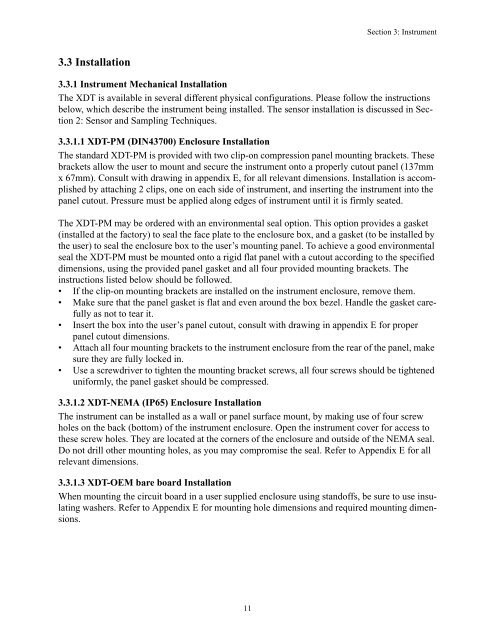
Section 3: Instrument3.3 Installation3.3.1 Instrument Mechanical InstallationThe <strong>XDT</strong> is available in several different physical configurations. Please follow the instructionsbelow, which describe the instrument being installed. The sensor installation is discussed in Section2: Sensor and Sampling Techniques.3.3.1.1 <strong>XDT</strong>-PM (DIN43700) Enclosure InstallationThe standard <strong>XDT</strong>-PM is provided with two clip-on compression panel mounting brackets. Thesebrackets allow the user to mount and secure the instrument onto a properly cutout panel (137mmx 67mm). Consult with drawing in appendix E, for all relevant dimensions. Installation is accomplishedby attaching 2 clips, one on each side of instrument, and inserting the instrument into thepanel cutout. Pressure must be applied along edges of instrument until it is firmly seated.The <strong>XDT</strong>-PM may be ordered with an environmental seal option. This option provides a gasket(installed at the factory) to seal the face plate to the enclosure box, and a gasket (to be installed bythe user) to seal the enclosure box to the user’s mounting panel. To achieve a good environmentalseal the <strong>XDT</strong>-PM must be mounted onto a rigid flat panel with a cutout according to the specifieddimensions, using the provided panel gasket and all four provided mounting brackets. Theinstructions listed below should be followed.• If the clip-on mounting brackets are installed on the instrument enclosure, remove them.• Make sure that the panel gasket is flat and even around the box bezel. Handle the gasket carefullyas not to tear it.• Insert the box into the user’s panel cutout, consult with drawing in appendix E for properpanel cutout dimensions.• Attach all four mounting brackets to the instrument enclosure from the rear of the panel, makesure they are fully locked in.• Use a screwdriver to tighten the mounting bracket screws, all four screws should be tighteneduniformly, the panel gasket should be compressed.3.3.1.2 <strong>XDT</strong>-NEMA (IP65) Enclosure InstallationThe instrument can be installed as a wall or panel surface mount, by making use of four screwholes on the back (bottom) of the instrument enclosure. Open the instrument cover for access tothese screw holes. They are located at the corners of the enclosure and outside of the NEMA seal.Do not drill other mounting holes, as you may compromise the seal. Refer to Appendix E for allrelevant dimensions.3.3.1.3 <strong>XDT</strong>-OEM bare board InstallationWhen mounting the circuit board in a user supplied enclosure using standoffs, be sure to use insulatingwashers. Refer to Appendix E for mounting hole dimensions and required mounting dimensions.11


