XDT Manual - Pioneer Air Systems Engineering
XDT Manual - Pioneer Air Systems Engineering
XDT Manual - Pioneer Air Systems Engineering
Create successful ePaper yourself
Turn your PDF publications into a flip-book with our unique Google optimized e-Paper software.
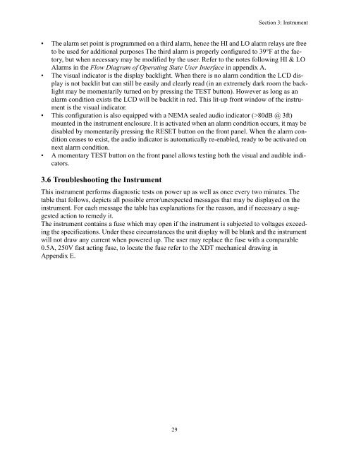
Section 3: Instrument• The alarm set point is programmed on a third alarm, hence the HI and LO alarm relays are freeto be used for additional purposes The third alarm is properly configured to 39°F at the factory,but when necessary may be modified by the user. Refer to the notes following HI & LOAlarms in the Flow Diagram of Operating State User Interface in appendix A.• The visual indicator is the display backlight. When there is no alarm condition the LCD displayis not backlit but can still be easily and clearly read (in an extremely dark room the backlightmay be momentarily turned on by pressing the TEST button). However as long as analarm condition exists the LCD will be backlit in red. This lit-up front window of the instrumentis the visual indicator.• This configuration is also equipped with a NEMA sealed audio indicator (>80dB @ 3ft)mounted in the instrument enclosure. It is activated when an alarm condition occurs, it may bedisabled by momentarily pressing the RESET button on the front panel. When the alarm conditionceases to exist, the audio indicator is automatically re-enabled, ready to be activated onnext alarm condition.• A momentary TEST button on the front panel allows testing both the visual and audible indicators.3.6 Troubleshooting the InstrumentThis instrument performs diagnostic tests on power up as well as once every two minutes. Thetable that follows, depicts all possible error/unexpected messages that may be displayed on theinstrument. For each message the table has explanations for the reason, and if necessary a suggestedaction to remedy it.The instrument contains a fuse which may open if the instrument is subjected to voltages exceedingthe specifications. Under these circumstances the unit display will be blank and the instrumentwill not draw any current when powered up. The user may replace the fuse with a comparable0.5A, 250V fast acting fuse, to locate the fuse refer to the <strong>XDT</strong> mechanical drawing inAppendix E.29


