TASKING C166/ST10 OCDS Debugging with CrossView Pro
TASKING C166/ST10 OCDS Debugging with CrossView Pro
TASKING C166/ST10 OCDS Debugging with CrossView Pro

Create successful ePaper yourself
Turn your PDF publications into a flip-book with our unique Google optimized e-Paper software.
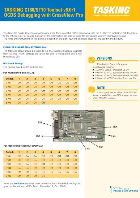
<strong>TASKING</strong> <strong>C166</strong>/<strong>ST10</strong> Toolset v8.0r1<strong>OCDS</strong> <strong>Debugging</strong> <strong>with</strong> <strong>CrossView</strong> <strong>Pro</strong>This Start-Up Guide describes all necessary steps for successful <strong>OCDS</strong> debugging <strong>with</strong> the <strong>C166</strong>/<strong>ST10</strong> toolset v8.0r1. It appliesto the Infineon XC16x boards, but part of the information can also be used for configuring your own hardware design.The hints and instructions in this guide are based on the Eight Queens example (queens), included in the product.EXAMPLES RUNNING FROM EXTERNAL RAMThe following steps should be taken to run the Queens (queenss) examplefrom external RAM. Settings are given for both a multiplexed and a nonmultiplexed bus.DIP-Switch SettingsThe correct board switch settings are:For Multiplexed Bus (MUX):Switch 1 2 3 4 5 6 7 8S101 Off Off Off Off Off On On OffS102 Off Off On Off Off Off Off OffS103 Off Off Off Off Off Off Off OffS104 On On Off Off Off Off Off OffS105 Off Off On On On On On OnS106 Off Off Off OffVERSIONSThis Start-Up Guide is based onthe following versions:• <strong>TASKING</strong> <strong>C166</strong>/<strong>ST10</strong> toolset, v8.0r1• Infineon XC161CJ Evaluation Board, rev 200• Infineon XC164CS Evaluation Board, rev 202B• Infineon XC167CI Evaluation Board, rev 200NOTEA Start-Up Guide for v7.5r6 of the <strong>TASKING</strong>toolset is available in the <strong>C166</strong> support sectionof the <strong>TASKING</strong> website.S106S104S101S105For Non Multiplexed Bus (DEMUX):Switch 1 2 3 4 5 6 7 8S101 Off On On Off Off Off Off OffS102 Off Off On Off Off Off Off OffS103 Off On Off Off Off Off Off OffS104 On On Off Off Off Off Off OffS105 Off Off On On On On On OnS106 Off Off Off OnS102S103Note: the bold blue switches mark deviations from the default settings asgiven in the Infineon XC16x Board Manual (v1.2, Oct. 2002).1<strong>OCDS</strong> <strong>Debugging</strong><strong>TASKING</strong> START-UP GUIDE
<strong>TASKING</strong> <strong>C166</strong>/<strong>ST10</strong> TOOLSETStartup Register SettingsThe correct system register settings for the Bus Configuration, External BusController and address selection should be set as follows:Register Multiplexed Bus Non Multiplexed BusSYSCON0 0x0000 0x0000SYSCON1 0x0000 0x0000VECSEG 0x0000 0x0000CPUCON1 0x0007 0x0007CPUCON2 0x8FBB 0x8FBBEBCMOD0 0x4022 0x6022FCONCS0 0x0031 0x0021TCONCS0 0x7A68 0x6240These registers are automatically set when the execution environment isselected as described in the next paragraph.EDE Quick StartIn the EDE the processor and target board must be selected. Theapplication must be configured so that the register values are set tomatch the board settings and memory must be configured. Thefollowing steps must be taken to achieve these settings and to geta successful debugger connection to the target board.1. Open the Queens projecta. Select the <strong>Pro</strong>ject menub. Select Set current and set queens.pjt as active project orright-click on the queens project in the <strong>Pro</strong>ject bar at the leftc. Select Set as Current <strong>Pro</strong>ject2. From the <strong>Pro</strong>ject menu, select <strong>Pro</strong>ject Options...2.1 a. In the left pane expand the Application entry and select<strong>Pro</strong>cessorb. Set <strong>Pro</strong>cessor to the XC16x processor that you usec. When the popup window shows up Click Yes to set the registers todefault values2.2 a. In the left pane select Memory Modelb. Set Memory Model to: smallc. Set Small model memorylayout to: Pagedd. Fill in the page numbers:DPP0: 0DPP1: 1DPP2: 42<strong>OCDS</strong> <strong>Debugging</strong><strong>TASKING</strong> START-UP GUIDE
<strong>TASKING</strong> <strong>C166</strong>/<strong>ST10</strong> TOOLSET2.3 a. In the left pane expand the Linker/Locator entry andselect Memoryb. Set Type=ROM, Start=0x0, End=0x069FFSet Type=RAM, Start=0x06A00, End=0x07FFFSet Type=RAM, Start=0x0C000, End=0x0CFFFSet Type=RAM, Start=0x10000, End=0x1FFFF2.4 a. In the left pane expand the <strong>CrossView</strong> <strong>Pro</strong> entry andselect Execution Environmentb. Set the Manufacturer to: Infineonc. Set the Execution environment to the evaluationboard and configuration you used. When the popup window shows up click Yes to set thestartup registers to new values2.5 Click on OK3. Rebuild the applicationa. Select the Build menub. Select Rebuild4. You can now start debugging <strong>with</strong> <strong>CrossView</strong> <strong>Pro</strong>a. Select the Build menub. Select DebugOutput of the queens example, shown by <strong>CrossView</strong> <strong>Pro</strong> DebuggerHARDWARE AND SOFTWARE BREAKPOINTSThe <strong>OCDS</strong> only has four hardware breakpoints available, which is often toolimited for debugging an application. With software breakpoints thislimitation does not exist. The usage of <strong>OCDS</strong> software breakpoints is limitedto 64k breakpoints. A software breakpoint is set by injecting DEBUGinstructions into the memory, so this is only possible <strong>with</strong>in RAM. Fordebugging code in EEPROM or FLASH memory only hardware breakpointscan be used.From <strong>CrossView</strong> <strong>Pro</strong> you can configure the use of hardware and softwarebreakpoints:a. Select Breakpoints menub. Select Breakpoints…c. Click on Preferences…3<strong>OCDS</strong> <strong>Debugging</strong><strong>TASKING</strong> START-UP GUIDE
<strong>TASKING</strong> <strong>C166</strong>/<strong>ST10</strong> TOOLSETd. You will now see the dialog from which you can configure the use ofbreakpoints.e. If your application is allocated in FLASH memory, select Hardwarebreakpoints onlyIf your application is allocated in RAM, select First hardwarebreakpoints then softwaref. Click OKg. Click OKTROUBLE SHOOTING1. <strong>CrossView</strong> <strong>Pro</strong> issues the following error:GdiInitIO(): <strong>OCDS</strong> module can't be enabled (connect cable or correctjumper setting)Solution: Set JP501 off -> on2. <strong>CrossView</strong> <strong>Pro</strong> issues the following error:GdiInitIO(): No valid JTAG cable found (target could be in Bootstrapmode)Solution: Set S103.4 on -> off3. Check the <strong>TASKING</strong> support web: www.tasking.com/support/<strong>C166</strong>-<strong>ST10</strong>NOTEThe <strong>OCDS</strong> has a limited number ofhardware breakpoints:• 4 code or data write breakpoints, ofwhich one can be used for a code rangeor data range read or write breakpoint• or 1 value write breakpointNOTEBy default the peripherals will notbe stopped upon a breakpoint.NOTEFor data breakpoints, <strong>CrossView</strong><strong>Pro</strong> will always use hardwarebreakpoints.JP501S103.4<strong>TASKING</strong>, the <strong>TASKING</strong> logo, Altium and the Altium logos are trademarks or registered trademarks of Altium Limited or itssubsidiaries. All other registered and unregistered trademarks referenced herein are the property of their respective ownersand no trademark rights to the same is claimed. Altium assumes no responsibility for any errors that may appear in thisdocument.© 2003, ALTIUM LIMITED4<strong>OCDS</strong> <strong>Debugging</strong><strong>TASKING</strong> START-UP GUIDE