ED-3 Electronic panel - Duro Dyne
ED-3 Electronic panel - Duro Dyne
ED-3 Electronic panel - Duro Dyne

You also want an ePaper? Increase the reach of your titles
YUMPU automatically turns print PDFs into web optimized ePapers that Google loves.
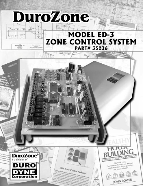
Cooling Limit PotentiometerThis potentiometer sets minimumtemperature allowed in cooling. If thesupply air temperature drops below theset Cooling Limit, the cooling is turned offand the indoor fan activated. After twominutes the cooling will be turned backon if the supply air has risen above theCooling Limit.W2 Timer PotentiometerSecond stage heating is controlled by atimer. If the <strong>panel</strong> has been calling forheating longer than the time set on theW2 Timer potentiometer, the second stageheating will be activated provided it is notinhibited by the Outdoor TemperatureLimit or the Capacity.Heat L<strong>ED</strong>The Heat L<strong>ED</strong> will be lit continuously whenthe <strong>panel</strong> is calling for first stage heating. TheHeat L<strong>ED</strong> will blink when the <strong>panel</strong> is callingfor second stage heating.Status L<strong>ED</strong>The Status L<strong>ED</strong> blinks continuously whenthe <strong>panel</strong> is powered and indicates the<strong>panel</strong>/microprocessor is operating properly.If the status L<strong>ED</strong> is on and not blinking, theautomatic contractor test is in progress.SA Limit L<strong>ED</strong>The SA Limit L<strong>ED</strong> is on continuously when aSupply Air Sensor is installed. The SA LimitL<strong>ED</strong> blinks when the <strong>panel</strong> is in supply airlimit status (Heating or Cooling temperatureexceeded).HEATSTATUSSA LMTODT Limit PotentiometerA low cost Outdoor Air Sensor can beused to monitor the outdoor temperatureand if the outdoor temperature is greaterthe ODT Limit, second stage heating isinhibited if the option was selected. In adual fuel heat pump, the ODT Limit isused to automatically switch the <strong>panel</strong> tothe secondary heating system.Damper L<strong>ED</strong>sThe green damper L<strong>ED</strong>s will light when thedamper is in the open position. A damperL<strong>ED</strong> will blink if it detects a zone thermostatis calling for both heating and cooling thatmay be caused by a shorted wire.System L<strong>ED</strong>sThe eight red L<strong>ED</strong>s indicate the status ofthe HVAC system. Each L<strong>ED</strong> will indicateby being lit continuously or blinking.Fan L<strong>ED</strong>The Fan L<strong>ED</strong> will be lit continuously whenthe <strong>panel</strong> is in continuous indoor fanoperation. The Fan L<strong>ED</strong> will blink whenthe system is in Purge mode.Cool L<strong>ED</strong>The Cool L<strong>ED</strong> will be lit continuouslywhen the <strong>panel</strong> is calling for cooling.FANCOOLODT Limit L<strong>ED</strong>The ODT Limit L<strong>ED</strong> is on continuously whenan Outdoor Air Sensor is installed. The ODTLimit L<strong>ED</strong> blinks when the <strong>panel</strong> is inhibitingsecond stage calls because of ODT Limit orthe dual fuel heat pump has switched to thesecondary heating system.Capacity Limit L<strong>ED</strong>The Capacity Limit L<strong>ED</strong> is on continuouslywhen the <strong>panel</strong> is inhibiting second stage callsbecause only one zone is calling for heating.Emergency Heating L<strong>ED</strong>The Emergency Heating L<strong>ED</strong> is on continuouslywhen the <strong>panel</strong> is in the emergency heat modeand will blink during an emergency heat call.ODT LIMITCAP LMTEM HEATWIRING INSTRUCTIONSAll wiring should be done in accordance with localand national codes. Use color-coded, multi-conductorthermostat wire.THESE PANELS ARE DESIGN<strong>ED</strong> FOR USE WITH24VAC CONTROLS AND SHOULD NOT BEUS<strong>ED</strong> WITH OTHER VOLTAGES. USE CAUTIONTO AVOID ELECTRIC SHOCK OR DAMAGE TOEQUIPMENT.Wiring Supply Air SensorTo install the optional Supply Air Sensor, connect twowires to the Supply Air Sensor and to the two terminalsmarked “SAS” on the <strong>panel</strong>.The Supply Air Sensor should be installed in the supplyduct so that it measures the supply air temperature.<strong>Duro</strong>Zone <strong>ED</strong>3 - INSTALLATION INSTRUCTIONS PAGE 5
Wiring Outdoor Air Temperature SensorTo install the optional Outdoor Air Temperature Sensor,connect two wires to the Outdoor Air Sensor and to thetwo terminals marked “OAS” on the <strong>panel</strong>.Wiring Zone DampersThe <strong>panel</strong> can be used with any 24VAC power open/powerclose or spring return damper. Terminal M1 is24VAC common, M2 is 24VAC, M4 is 24VAC when the<strong>panel</strong> opens the damper and M6 is 24VAC when the <strong>panel</strong>closes the damper.<strong>ED</strong>3PanelThe Outdoor Air Temperature Sensor should be installedoutside and in a shaded location.Wiring Zone ThermostatsAll zones can use low cost, heat-cool thermostats as shownbelow. Be sure to set DIP switch #4 to HC if a heat-coolthermostat is used in Zone1.Wiring diagram for <strong>Duro</strong>Zone MB, MS, or RD typedamper.<strong>ED</strong>3Panel<strong>ED</strong>3PanelWiring diagram for spring return damper that is normallyclosed with no power (spring closed).<strong>ED</strong>3Panel<strong>ED</strong>3PanelA heat pump thermostat can be used in Zone1 to provideemergency heat control from the thermostat. Be sure toset DIP switch #4 to HP.Wiring diagram for spring return damper that is normallyopen with no power (spring open).Heat-Pump ThermostatZone1WEYOCR<strong>ED</strong>3PanelW2/EG<strong>ED</strong>3PanelY1OW1/BCR<strong>Duro</strong>Zone <strong>ED</strong>3 - INSTALLATION INSTRUCTIONS PAGE 6
Wiring HVAC EquipmentThe <strong>panel</strong> can be used with a wide variety of HVAC systems.Some of the more common configurations follow:COMPRESSORLINEVOLTAGEGAS VALVEINDOOR FANCYWSINGLE STAGEGAS/ELECTRIC SYSTEMGR24VACCCOMPRESSORGAS VALVELINEVOLTAGECYGTWO STAGEGAS/ELECTRIC SYSTEMW1W2R24VACC <strong>ED</strong>3 PanelGW2/EY1W1/BRCRHRH-RC20M OPSYS NO JUMPERYES ODLMT NOYES C LMT NONO PRGE 90SHP TSTAT HCEL FAN GASDF HP CONHP SYS HCO<strong>ED</strong>3 PanelGW2/EY1W1/BORCRHRH-RC20M OPSYS NO JUMPERYES ODLMT NOYES C LMT NONO PRGE 90SHP TSTAT HCEL FAN GASDF HP CONHP SYS HCHEAT PUMPCOMPRESSORREVERSING VALVE(COOLING)LINEVOLTAGE24VACDEFROSTAIR HANDLERINDOOR FAN24VACELECTRIC STRIPHEAT PUMP24VACCOMPRESSORREVERSING VALVE(COOLING)DEFROSTCRYOWCRGWCRYOW <strong>ED</strong>3 PanelGW2/EY1W1/B20M OPSYS NOYES ODLMT NOYES C LMT NONO PRGE 90SHP TSTAT HCEL FAN GASDF HP CONHP SYS HCORCRHRH-RCJUMPERCut Jumper<strong>ED</strong>3 PanelGW2/EY1W1/BORCRHCOMPRESSORINDOOR FANLINEVOLTAGEFURNACECYGR24VACC<strong>ED</strong>3 PanelGW2/EY1W1/BORCRHRH-RCJUMPERCut JumperFURNACELINEVOLTAGEINDOOR FAN1 STAGE HEATINGC24VACRGW1RH-RCJUMPERCut JumperBURNERCIRCULATORRELAY OR HOTWATER VALVE 20M OPSYS NOYES ODLMT NOYES C LMT NONO PRGE 90SHP TSTAT HCEL FAN GASDF HP CONHP SYS HC*NOTE 1: Some air handlers or furnaces require theY teminal wired to them for fan speeds.2 STAGE HEATINGFAN SPE<strong>ED</strong>W2Y 20M OPSYS NOYES ODLMT NOYES C LMT NONO PRGE 90SHP TSTAT HCEL FAN GASDF HP CONHP SYS HC<strong>Duro</strong>Zone <strong>ED</strong>3 - INSTALLATION INSTRUCTIONS PAGE 7