Duro Zone - Duro Dyne
Duro Zone - Duro Dyne
Duro Zone - Duro Dyne
- No tags were found...

Create successful ePaper yourself
Turn your PDF publications into a flip-book with our unique Google optimized e-Paper software.
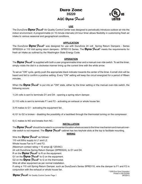
<strong>Duro</strong> <strong>Zone</strong>35220AQC Dyna-Fresh ®USEThe <strong>Duro</strong><strong>Zone</strong> Dyna-Fresh ® Air Quality Control Center was designed to periodically introduce outdoor air into theindoor environment. A programmable (in 15 minute intervals) 24 hour timer allows flexibility in customizing fresh airintake to various seasonal and geographical conditions.APPLICATIONThe <strong>Duro</strong><strong>Zone</strong> Dyna-Fresh ® was designed for use with <strong>Duro</strong><strong>Zone</strong> 24 volt Spring Return Dampers - SeriesSPRD024 or 110 Volt spring return dampers - SPRD110 Series. The Dyna-Fresh ® meets the requirements forfresh air intake as outlined by the Washington State Energy Code.OPERATIONThe Dyna-Fresh ® is supplied with both a user programmable timer and a manual over-ride switch. To set the timer,simply rotate the dial in a clockwise manner lining up the current time with the white arrow.To set an "ON" cycle, gently push the appropriate black indicator towards the center of the timer. A small click will beheard and felt to confirm a positive setting. Every "ON" setting will keep the circuit energized for a period of fifteenminutes.When the Dyna-Fresh ® is put into an "ON" state, either by the timer setting or the manual over-ride switch, thefollowing occurs:1) 24 volts is sent to terminals D1 and D4 - opening a spring return damper.2) 110 volts is sent to terminals F1 and F2 - activating an exhaust or whole house fan.3) R makes to G1 - activating the equipment fan.4) G1 to G2 is broken - disabling the possibility of a backfeed through the thermostat turning on the compressor.5) C makes to NO and breaks from NC.INSTALLATIONThe Dyna-Fresh ® should be located in a convenient location where access to the timer mechanism and manual overrideswitch is not impaired. The Dyna-Fresh ® cabinet has two keyhole slots at the top to facilitate mounting.WIRINGWire the Dyna-Fresh ® as follows:110 volt 60hz supply to L1 and L2.Whole house Fan to F1 and F2.(Maximum contact rating = 10 amps @ 120VAC)24 volt <strong>Duro</strong><strong>Zone</strong> Spring Return Damper (SPRD024), to D1 and D4.R on the Dyna-Fresh ® to R on the equipment.G1 on the Dyna-Fresh ® to G on the equipment.G2 on the Dyna-Fresh ® to G on the thermostat.Wire all other equipment as per normal installation.If using a 110 volt Spring Return Damper, such as <strong>Duro</strong><strong>Zone</strong>'s Series SPRD110, wire the damper to F1 and F2 inconjunction with the exhaust or whole house fan.©2009 <strong>Duro</strong> <strong>Dyne</strong> CorporationPrinted in USA 02/2009Dyna-Fresh ® Air Quality Control Center Page 1BP035413
Dyna-Fresh ® AIR QUALITY CONTROL CENTERWholeHouseFan110 Volt Input(Optional)110 VoltSpringReturnDamperF1 F2 L1 L2D1 D4 R G1 G2 NO C NCG on ThermostatG on EquipmentR on EquipmentWhen clock makes (or manual switch is made):24 volts is sent to D1 and D4110 volts is sent to F1 and F2 (maximum contact rating = 10 AMP @ 120 VAC)R makes to G1Connection between G1 and G2 is brokenNO makes to CWhen using 110 volt damper, wire motor to F1 and F2 with whole housefan (if used) and leave D1 and D4 blank.1424 VoltSpringReturnDamperInternal 24 volt transformer is fused on primary and secondary sides.Dyna-Fresh ® ALTERNATIVE WIRING USING EXISTING BATHROOM FAN TOEXHAUST STALE AIR110 Volt Input(Optional)110 VoltSpringReturnDamperF1 F2 L1 L2D1 D4 R G1 G2 NO C NCG on ThermostatG on EquipmentR on EquipmentBathroomExhaustFanBathroomWallSwitch110 Volts1424 VoltSpringReturnDamper