H-335 Manual - WaterLOG
H-335 Manual - WaterLOG
H-335 Manual - WaterLOG

You also want an ePaper? Increase the reach of your titles
YUMPU automatically turns print PDFs into web optimized ePapers that Google loves.
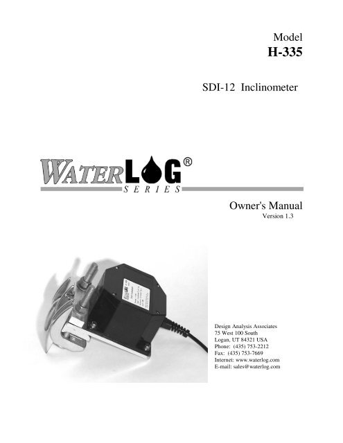
ModelH-<strong>335</strong>SDI-12 InclinometerOwner's <strong>Manual</strong>Version 1.3Design Analysis Associates75 West 100 SouthLogan, UT 84321 USAPhone: (435) 753-2212Fax: (435) 753-7669Internet: www.waterlog.comE-mail: sales@waterlog.com
(c) What DESIGN ANALYSIS Will DoDESIGN ANALYSIS will repair the PRODUCT or will endeavor to provide a replacement ofsame within a reasonable period of time. In the event that DESIGN ANALYSIS is unable to makethe necessary repairs or replacement within a reasonable period of time, the original purchase pricewill be refunded upon the return of the PRODUCT to DESIGN ANALYSIS.(d) Limitations(i)(ii)THE ENTIRE REMEDY FOR BREACH OF THIS LIMITED WARRANTY SHALLBE LIMITED TO REPLACEMENT OF THE DEFECTIVE PRODUCT ORREFUNDING OF THE PURCHASE PRICE, AS SET FORTH ABOVE. IN NOEVENT WILL THE LIABILITY OF DESIGN ANALYSIS TO USER OR TO ANYOTHER PARTY EXCEED THE ORIGINAL PURCHASE PRICE OF THE PRODUCT,REGARDLESS OF THE FORM OF THE CLAIM.EXCEPT FOR THE EXPRESS WARRANTIES ABOVE, DESIGN ANALYSISSPECIFICALLY DISCLAIMS ALL OTHER WARRANTIES, INCLUDING,WITHOUT LIMITATION, ALL IMPLIED WARRANTIES OF MERCHANTABILITYAND FITNESS FOR A PARTICULAR PURPOSE.(iii) UNDER NO CIRCUMSTANCES WILL DESIGN ANALYSIS BE LIABLE FORSPECIAL, INCIDENTAL, CONSEQUENTIAL, INDIRECT, OR ANY OTHERDAMAGES OR CLAIMS ARISING FROM THE USE OF THIS PRODUCT, THISINCLUDES LOSS OF PROFITS OR ANY OTHER COMMERCIAL DAMAGES,EVEN IF ADVISED OF THE POSSIBILITY OF SUCH DAMAGES. IN NO EVENTWILL DESIGN ANALYSIS BE LIABLE FOR ANY CLAIMS, LIABILITY, ORDAMAGES ARISING FROM MODIFICATION MADE THEREIN, OTHER THANBY DESIGN ANALYSIS.(iv) THIS LIMITED WARRANTY GIVES USER SPECIFIC LEGAL RIGHTS. USERMAY ALSO HAVE OTHER RIGHTS WHICH VARY FROM STATE TO STATE.SOME STATES DO NOT ALLOW LIMITATIONS ON HOW LONG AN IMPLIEDWARRANTY LASTS OR THE EXCLUSION OF INCIDENTAL ORCONSEQUENTIAL DAMAGES, SO THOSE LIMITATIONS OR EXCLUSIONSMAY NOT APPLY.6. GOVERNING LAWThis Agreement and its validity and interpretation shall be governed by the laws of the State of Utah,notwithstanding any choice of law rules of Utah or any other state or jurisdiction.W-2 User Agreement/WATERLOG ® Warranty H-355
Chapter 1H-<strong>335</strong> Operation1.1 OperationThe WATERLOG ® H-<strong>335</strong> is a precision, single axis, wide range inclinometer which measures the angle(position) of radial water control gates. The H-<strong>335</strong> is easy to use, works with any data recorder/logger witha SDI-12 interface and can be interfaced with SCADA systems. The “Serial-Digital Interface” is ideal fordata logging applications with the following requirements:Multiple sensors on a 3-wire busLow system costUp to 200 feet of cable between a sensor and the data recorderThe H-<strong>335</strong> has the following features:Easily attaches to I-beam of gate structureGravity referenced sensor allows installation anywhere on the gate structureScales the gate position into user units of feet, inches, meters, etc.Built-in intelligence automatically calculates both gate height and arc lengthNo hysteresis or backlash0.03 accuracy over full position and temperature rangeSealed water-tight enclosureNo moving parts or bearingsCopan Lake, OklahomaChouteau Lock and Dam, OklahomaH-<strong>335</strong> H-<strong>335</strong> Operation 1-1
1.2 Theory of OperationThe H-<strong>335</strong> has a single axis tilt sensor, signal processing circuitry, 14-bit analog to digital converter and amicroprocessor. The sensor is a ceramic based electrolytic tilt sensor which provides high resolution andvery good linearity. The sensor is constructed as a hermetically sealed ceramic cavity with electrodespartially submerged in a conductive fluid. The ratio between submersed areas of the facing electrodes isproportional to the inclination angle. The electronics provide an AC sensor excitation together with aprecision, ratiometric peak-hold detector. Because scale factor of electrolytic sensors is sensitive totemperature, the H-<strong>335</strong> has a built-in digital temperature sensor. The microprocessor uses a mathpolynomial to correct for temperature induced effects and any non-linear characteristics of sensor.1.3 Problems with Winch Mechanism and Existing Measurement SystemsTainter gates are typically controlled with a motor operated winch mechanism. The gear box for the winchhas a “sundial” scale and pointer which shows the current gate opening. Often the mechanism also has aselsyn transmitter which allows the gate position to be monitored in a nearby control room. The sundial andselslyn driven scales are usually marked in units of “feet”. Unfortunately most winch mechanisms have noprovisions for monitoring the gate position with a data logger or SCADA (System Control and DataAcquisition) system. In the past, users have tried using incremental shaft encoders connected to the winchwith a sprocket and chain. This technique has the following shortcomings: The radius of the winch drum changes as the cable winds up, giving a non-linear readout. The lift cables stretch as the gate is raised off the sill. The backlash (hysteresis) in the drive chain between the winch drum and encoder can be large. Each installation requires custom mechanisms, enclosures and setup. The winch shaft is not accessible on some gearboxes.The H-<strong>335</strong> overcomes many of the problems associated with measuring the position of a tainter gate bydirectly monitoring the angle of the gate structure. Backlash and non-linear effects of the winch drum andcables are completely bypassed.1-2 IntroductionH-<strong>335</strong>
1.4 Gate GeometryMost users are interested in measuring the gate opening or “height”. Upon closer examination, however, thegeometry of a tainter gate is somewhat complex. The following definitions and illustration shows thegeometry of a typical tainter gate.1.4.1 Terms and DefinitionsTrunnion Bearing:Sill Elevation:Gate Radius:Gate Angle:Gate Arc Length:Gate Height:Sill Angle:The pivot point of the gate structure.The elevation relative to a datum of the point where the gate seals against thebottom of the spillway.The distance between the center of the trunnion bearing and the outside of the gateskin plate.The angle, in degrees, through which the gate has opened (0 = closed).The distance the gate face moves through the partial curve of a circle.The vertical distance between the bottom of the gate and a horizontal line passingthrough the sill.The angle, in degrees, between a horizontal line through the trunnion bearing andthe point at which the gate rests on the spillway.The tilt sensor in the H-<strong>335</strong> measures the angle of the gate structure referenced to gravity. The H-<strong>335</strong> canbe installed anywhere on the gate structure since the entire structure rotates the same relative to gravity.The sensor does not need to be on the center of the gate’s rotating axis.The H-<strong>335</strong> measures and reports the UserAngle relative to the closed position (0 = closed). Forconvenience, the H-<strong>335</strong> also internally calculates and reports GateHeight and GateArcLength. Normally,users program their data recorder to record only one of the three parameters. Each of these threemeasurement parameters has advantages and disadvantages:H-<strong>335</strong> H-<strong>335</strong> Operation 1-3
Figure 1 Gate Geometry1.4.2 User AngleThe UserAngle is the angle, in degrees, thru which the gate has moved relative to the closed position. Allother calculations are based on this measurement. Some dams have a spillway which slopes rapidlydownward from the point where the gate contacts the sill. For these structures, the water flow calculation isa complex geometric problem because the actual weir opening (distance between the gate and the spillway)changes as the vertical point from the bottom of the gate first moves upward, then down the incline of thespillway. For complex gate geometries, program your data logger to record the UserAngle and do thenecessary calculations during post-processing of the data. The UserAngle parameter is calculated internallyin the H-<strong>335</strong> using the following equation:UserAngle = (SensorAngle × UserSlope) - UserOffsetThe UserSlope is a constant set to either +1.0 or -1.0 and must be programmed into the H-<strong>335</strong> atinstallation (see Section 1.8). The UserOffset value is automatically calculated when the extended “aXZO”command is issued after the installation is completed.1-4 IntroductionH-<strong>335</strong>
1.4.3 Arc LengthThe ArcLength is distance the gate face moves through the partial curve of a circle. Normally this value isnot recorded by the data logger. The H-<strong>335</strong> calculates and reports this value for field test and verificationpurposes and is calculated internally in the H-<strong>335</strong> using the following equation:GateArcLength = UserAngle × π × GateRadius180If water is flowing through the gate, the GateHeight cannot be directly measured with a measuring tapebecause the water flow sweeps the tape away. However, if the tape is attached to the face of the gate, and istangent to the gate, the Arc Length can be directly measured in the field.1.4.4 Gate HeightThe GateHeight is the vertical distance between the bottom of the gate and a horizontal line passing thruthe sill. Normally this value is recorded and used in a weir calculation to determine water flow. TheGateHeight parameter is calculated internally in the H-<strong>335</strong> using the following equation:GateHeight = GateRadius sin SillAngle[ ( ) − sin( SillAngle - UserAngle)]The GateRadius and SillAngle are constants and must be programmed into the H-<strong>335</strong> during installation.1.5 Programming the Data RecorderYou must prepare your data recorder to receive and record the H-<strong>335</strong> data. Since data recorders differwidely, refer to your recorder manufacturer's directions. In general, program the data recorder to input fourvalues via the SDI-12 port. Usually only one or two of the parameters is actually recorded. Your datarecorder must issue an “aM!” command, then collect the data with a “aD0 ” command, as explained inChapter 2. The H-<strong>335</strong> places four data values in its data buffer:Where:a+AA.AA+BB.BB+CC.CC+DD.DD+AA.AA = GateArcLength (inches, meters etc.)+BB.BB = GateHeight (inches, meters etc.)+CC.CC = UserAngle (Degrees of angle)+DD.DD = SensorTemperature (C)H-<strong>335</strong> H-<strong>335</strong> Operation 1-5
1.6 InstallationSince the H-<strong>335</strong> is a gravity referenced tilt sensor, it can be installed anywhere on the gate structure. TheH-<strong>335</strong> must be installed exactly vertical and in the plane the tainter gate rotates. If the H-<strong>335</strong> is not verticalthe senor will suffer an off-axis trigonemetric error as the gate is raised. The mount clamp has a 2-axisgimbal which allows the inclinometer to be adjusted to compensate for camber in the gate structure.The best place to install the sensor is near the trunnion bearing between the I-beam of the gate arm and theconcrete pier. Either the left or right arm will work. This location is protected from direct sunlight, logs anddebris, and allows for a short cable. The beam clamps allow easy installation with no drilling and will workfor beams up to 2.0 inches thick. Make certain the cable has sufficient slack for the entire rotation of thegate.The UserAngleSlope coefficient in the H-<strong>335</strong> must be programmed appropriately depending on whether theH-<strong>335</strong> is installed on the left or right arms of a gate and whether on the inside or outside of the I-beam (seeFigure 2).1.7 Making Connections to the H-<strong>335</strong>Since the H-<strong>335</strong> is normally exposed to the sun and weather, a cable rated for water immersion andsunlight resistance is required. A black urethane or similar sunlight/waterproof rated cable is recommended.Make certain the power is OFF before making any connections. To access the wiring terminal block, openthe cover of the H-<strong>335</strong> by removing the four cover screws. Whenever tightening or loosening the coverscrews, turn each screw only a turn or two at a time. Try to equalize the stress on the lid. This is especiallyimportant when the O-ring in the lid is near full compression.Make certain the cable properly seals in the grommet of the liquid-tight cable fitting and that the O-ring inthe fitting is tight against the box. The connection must be water tight. Other grommet diameters andfittings are available from the factory.The H-<strong>335</strong> has a removable 4-pin wiring terminal block for connecting the SDI-12 cable. Unplug theterminal block and make the connections to the cable. The connections are labeled on the circuit board.Check to make certain the connections are correct, then plug the terminal block into the H-<strong>335</strong> circuit1-6 IntroductionH-<strong>335</strong>
oard. This eliminates stressing the connector and circuit board while tightening the terminal block screws.Make certain the wires do not touch any of the internal components, especially if your cable has a baredrain wire.1.8 Programming the H-<strong>335</strong>The H-<strong>335</strong> has several fixed constants which must be programmed before installation. We recommenddoing this in the lab, before installing the H-<strong>335</strong> on the tainter gate.Step 1:Program the sensor with the proper SDI-12 address, make certain each sensor has a uniquesensor address. See Chapter 2 for details of the “aAn” change address command.The H-<strong>335</strong> comes from the factory with the following settings:Sensor Address: 0UserAngleSlope: +1.0UserAngleOffset: 0.0GateRadius: 36.0SillAngle: 51.057With these values the GateHeight and GateArcLength parameters will be in units of feet for a gate with aradius of 36.0 feet. The setup is stored in EEPROM within the H-<strong>335</strong> and will not be lost if the power isdisconnected. The extended commands for changing these settings is described in detail in Chapter 2.Use the extended SDI-12 commands “aXWCn” and “AaXRCn” to write and read respectively thefollowing settings:Step 2 (coefficient 1): Set the UserAngleSlope as needed for your installation. Set the slope to +1.0for a gate which opens clockwise while facing the H-<strong>335</strong> cover. Set the slope to-1.0 for a gate which opens counter-clockwise while facing the sensor cover(see Figure 2).Step2 (coefficient 2): Make certain the UserAngleOffset value is set to 0.0.Step3 (coefficient 3): Set the GateRadius as needed for your tainter gate. This is the distance betweenthe center of the trunnion bearing and the outside face of the skin plate. This value also determines the unitsfor the GateArcLength and GateHeight data output values. If this value is in units of feet, the data outputwill be in units of feet etc.Step4 (coefficient 4): Set the SillAngle as needed for your tainter gate. Use a calculator and thefollowing formula to compute the proper value:SillAngle = ArcSinTrunnionElevation -SillElevationGateRadiusFor Example:ArcSin 391'-363' = 51057 . 36' H-<strong>335</strong> H-<strong>335</strong> Operation 1-7
1.9 Installing the H-<strong>335</strong> and setting the mechanical sensor offsetThe tilt sensor in the H-<strong>335</strong> has a physical ±40 calibrated range. This allows sufficient dynamic range tomeasure a gate which opens up to 80. To work properly, the sensor must be mechanically adjusted duringinstallation to preserve the available physical dynamic range. This is done by loosening two screws androtating the internal sensor assembly. The mechanical offset adjustments are made while monitoring theSensorAngle parameter. This is the raw sensor reading with no adjustment for slope or offset. TheUserAngle parameter is processed with a slope and offset term to produce the more useful 0.0 to +80.0reading for the data recorder.With the gate closed the mechanical offset must be set near (but not beyond) one end of the sensor’smeasurement range. The proper setting depends on which gate arm the H-<strong>335</strong> is installed and which side ofthe I-beam the H-<strong>335</strong> is mounted (see Figure 2). For example; with a gate which can open up to 70 andwhich the inclinometer rotates clockwise (while facing the H-<strong>335</strong> cover) as the gate opens, the sensorshould be rotated until SensorAngle reads ~ -35. When this gate is fully open the raw SensorAngle willread +35. With the same gate but with the inclinometer installed such that it rotates counter-clockwise(while facing the H-<strong>335</strong> cover) as the gate opens, the sensor must be mechanically adjusted to +35. Whenthis gate is fully open the raw SensorAngle will read -35.The H-<strong>335</strong> fiberglass enclosure can be installed in anyposition in the plane of rotation. If possible, locate theconnector on the bottom to prevent water from standingon the connector. The internal ceramic sensor elementis symmetrical and will still make measurements ifinstalled upside down. However, if the sensor is upsidedown, the calibration will be invalid, the slope will bewrong and the output data confusing. Check to makecertain the wires exit the red plastic cover at the 2:00o’clock position when the gate is in the center of itstravel arc.1-8 IntroductionH-<strong>335</strong>
Figure 2 Installation ConfigurationsIn practice the following steps must be done with two people. One working on the gate pier and the other onthe dam catwalk with a data logger or laptop computer connected to the SDI-12 bus. A hand held radiomakes it easier to communicate be between the two workers. During the installation procedure theSensorAngle must be monitored in real time. Ignore the UserAngle value at this time. The offset adjustmentcan be done in two ways:H-<strong>335</strong> H-<strong>335</strong> Operation 1-9
1.9.1 Method IIssue repeated SDI-12 “aM1” and “aD0” commands.For the “aM1” command, the H-<strong>335</strong> places 6 parameters in its data buffer where:a = Sensor Address (0-9,A-Z)+AA.AA = UserAngle (degrees of angle)+BB.BBB = SensorAngle (degrees of angle)+CCCC = Raw A/D Positive Count (±8192)+DDDD = Raw A/D Negative Count (±8192)+EEEE = Raw A/D Positive Count (±16384)+FF.FF = SensorTemperature (C)1.9.2 Method IIUse the “aXTEST” command (see Chapter 2).This command is primarily used for production testing and requires the use of a H-419 Sidekick interfaceand a PC. This command causes the H-<strong>335</strong> to transmit unsolicited real-time data for testing purposes. Thisis not compliant with the SDI-12 specification and is not used with data loggers.XTEST continually prints the following parameters in a single line:For example:Sensor Address (0-9, A-Z)SensorAngle (Angle)1 +1.2001 +1.2001 +1.5001 +1.7001 +1.900etc.Step 5:Step 6:Step 7:Remove the cover from the H-<strong>335</strong> and make the wiring connections. Leave the cover off, donot bolt the assembly to the I-beam at this time.Connect the +12V power. Issue an “aI” identifiy command to make certain the sensor isconnected and working.Make certain the tainter gate is fully closed and resting on the sill.1-10 IntroductionH-<strong>335</strong>
Step 8:Slightly loosen the two #4-40 allen socket head screws which retain the ceramic sensorassembly. Some dams have the tainter gate I-beam located above the platform on the concretepier. If you can access the sensor after installation, follow steps 9a-11a. If you cannot accessthe sensor when it is bolted to the I-beam, follow steps 9b-11b.For Installations where the sensor is accessibleStep 9a:Step 10a:Step 11a:Tightly bolt the H-<strong>335</strong> to the I-beam with the beam clamps.Use the data logger or laptop computer to monitor the SensorAngle. Carefully rotate theinternal sensor assembly for the desired value. Make certain the internal ceramic sensor is notupside down. Sensors mounted such that the inclinometer rotates clockwise as the gate opensmust be set to -34to -38. Sensors mounted such that the inclinometer rotates counterclockwiseas the gate opens must be set to +34to +38. The adjustment is quite sensitive andrequires a bit of patience. When the desired setting is reached, tighten the two allen screws.Re-install the cover and proceed to Step 12. Whenever tightening or loosening the coverscrews, turn each screw only a turn or two at a time. Try to equalize the stress on the lid. Thisis especially important when the O-ring in the lid is near full compression.For Installations where the sensor is NOT accessibleStep 9b:Step 10b:Step 11b:Temporarily rest the H-<strong>335</strong> flush against the top of the I-Beam while holding it exactlyvertical.Use the data logger or laptop computer to monitor the SensorAngle. Carefully rotate theinternal sensor assembly for the desired value. Make certain the internal ceramic sensor is notupside down. Sensors mounted such that the inclinometer rotates clockwise as the gate opensmust be set to -34to -38. Sensors mounted such that the inclinometer rotates counterclockwiseas the gate opens must be set to +34to +38. The adjustment is quite sensitive andrequires a bit of patience. When the desired setting is reached, tighten the two allen screws.The angle setting can be approximate because it is more accurately fine tuned in the next step.Re-install the cover. Whenever tightening or loosening the cover screws, turn each screw onlya turn or two at a time. Try to equalize the stress on the lid. This is especially important whenthe O-ring in the lid is near full compression. Loosely bolt the H-<strong>335</strong> to the I-beam with thebeam clamps. While monitoring the SensorAngle fine tune the angle by tapping or prying thealuminum mounting plate with a screw driver. When the desired angle is obtained, tighten thebeam clamp bolts.H-<strong>335</strong> H-<strong>335</strong> Operation 1-11
Test the InstallationStep 12:Step 13:Step 14:Check to make certain the sensor is still at the desired SensorAngle. Make certain the gate isfully closed and resting on the sill. Wait at least 15 minutes or so for the sensor temperatureto stabilize before proceeding to the next step.Issue the extended “aXZO” Zero Offset command. The H-<strong>335</strong> will make a fresh anglemeasurement and use this value to automatically update the UserAngleOffset value toproduce a UserAngle reading = 0.0 .Make a “aM” measurement. The GateArcLength, GateHeight and UserAngle parametersshould all be zero. Raise the gate and check for proper (increasing) readings.The SDI-12 “aM” command makes the following measurements:Where:a +AA.AA+BB.BB+CC.CC+DD.DDa = Sensor Address (0-9, A-Z)+AA.AA = GateArcLength (inches, meters etc.)+BB.BB = GateHeight (inches, meters etc.)+CC.CC = UserAngle (degrees of angle)+DD.DD = SensorTemperature (C)This completes installation and testing of the H-<strong>335</strong>.1-12 IntroductionH-<strong>335</strong>
2.2 Measure CommandThe Measure Command causes a measurement sequence to be performed. The H-<strong>335</strong> supports three differentmeasure commands (“aM”, “aM1" and “aM2"). Data values generated in response to this command are storedin the sensor's buffer for subsequent collection using "D" commands. The data will be retained in the sensoruntil another "M", “C” or "V" command is executed.Command Response Description------------------ ---------------------- ------------------------------------"aM!" "atttn" Initiate measurementWhere:a is the sensor address ("0-9", "A-Z", "a-z", "*", "?").Mtttnis an upper-case ASCII characteris a three digit integer (000-999) specifying the maximum time, in seconds,the sensor will take to complete the command and have measurement dataavailable in its buffer.is a single digit integer (0-9) specifying the number of values thatwill be placed in the data buffer. If "n" is zero (0), no data will beavailable using subsequent "D" commands.Upon completion of the measurement, a service request "a" is sent to the data recorder indicating thesensor data is ready. The data recorder may wake the sensor with a break and collect the data anytime afterthe service request is received or the specified processing time has elapsed.Example of a H-<strong>335</strong> "aM!" command:Command Response Time Values Description"aM!" "a0034" 3 sec 4 Make current measurementSubsequent Command"aD0"Responsea+AA.AA+BB.BB+CC.CC+DD.DDWhere:AA.AABB.BBCC.CCDD.DD= Gate Arc Length= Gate Height= User Angle (Degrees)= Sensor Temperature (C)2-2 SDI-12 Command and Response ProtocolH-<strong>335</strong>
“aM1" CommandExample of a H-<strong>335</strong> "aM1!" command:Command Response Time Values Description"aM1!" "a0036" 3 sec 6 Make measurementSubsequent Command"aD0"Responsea+AA.AA+BB.BBB+CCCC+DDDD+EEEE+FF.FFWhere:+AA.AA = User Angle+BB.BBB = Sensor Angle+CCCC = Raw A/D Positive Count (±8192)+DDDD = Raw A/D Negative Count (±8192)+EEEE = Raw A/D Count (±16384)+FF.FF = Sensor Temperature (C)“aM2" CommandExample of a H-<strong>335</strong> "aM2!" command:Command Response Time Values Description"aM2!" "a0031" 3 sec 1 Make measurementSubsequent Command"aD0"Responsea+AA.AAWhere:+AA.AA= Gate HeightH-<strong>335</strong> SDI-12 Command and Response Protocol 2-3
2.3 Concurrent Measure CommandThis is a new command for the Version 1.2 SDI-12 Specification. A concurrent measurement is one whichoccurs while other SDI-12 sensors on the bus are also taking measurements. This command is similar to the“aM!” command, however, the nn field has an extra digit and the sensor does not issue a service request whenit has completed the measurement. Communicating with other sensors will NOT abort a concurrentmeasurement. Data values generated in response to this command are stored in the sensor's buffer forsubsequent collection using "D" commands. The data will be retained in the sensor until another "M", “C” or"V" command is executed.Command Response Description"aC!" "atttnn" Initiate measurementWhere:a is the sensor address ("0-9", "A-Z", "a-z", "*", "?").Ctttnnis an upper-case ASCII characteris a three digit integer (000-999) specifying the maximum time, in seconds,the sensor will take to complete the command and have measurement dataavailable in its buffer.is a two digit integer (00-99) specifying the number of values that willbe placed in the data buffer. If "n" is zero (0), no data will be availableusing subsequent "D" commands.The data recorder may wake the sensor with a break and collect the data anytime after the specified processingtime has elapsed.2-4 SDI-12 Command and Response ProtocolH-<strong>335</strong>
2.4 Send Data CommandThe Send Data command returns sensor data generated as the result of previous "aM!", aM1!", aM2!", “aC!”or "aV!" commands. Values returned will be sent in 33 characters or less. The sensor's data buffer will notbe altered by this command.Command"aD0!" through "aD9!"Response"apd.d ... pd.d"Where:a is the sensor address ("0-9", "A-Z", "a-z", "*", "?").D0..D9 are upper-case ASCII characters.p Is a polarity sign (+ or -)d.drepresents numeric digits before and/or after the decimal. A decimal may be used inany position in the value after the polarity sign. If a decimal is not used, it will beassumed to be after the last digit.For example: +3.29 +23.5 -25.45 +300If one or more values were specified and a "aD0!" returns no data (a only), it means that themeasurement was aborted and a new "M" command must be sent.Example of a H-<strong>335</strong> "aD0!" command:Previous command"aM!"Subsequent Command"aD0"Response"a0034"Responsea+AA.AA+BB.BB+CC.CC+DD.DDWhere:AA.AABB.BBCC.CCDD.DD= Gate Arc Length= Gate Height= User Angle (Degrees)= Sensor Temperature (C)H-<strong>335</strong> SDI-12 Command and Response Protocol 2-5
2.5 Continuous MeasurementsThis is a new command for the Version 1.2 SDI-12 Specification. Sensors that are able to continuously monitorthe phenomena to be measured, such as a cable position, do not require a start measurement command. Theycan be read directly with the R commands (R0!...R9!). The R commands work exactly like the D (D0!...D9!)commands. The only difference is that the R commands do not need to be preceded with an M command. TheH-<strong>335</strong> DOES NOT supports the aR0! continuous measurement commands.2.6 Initiate Verify CommandThe Verify Command causes a verify sequence to be performed. The result of this command is similar to the"aM!" command except that the values generated are fixed test data and the results of diagnostic checksumtests. The data generated in response to this command is placed in the sensor's buffer for subsequent collectionusing "D" commands. The data will be retained in the sensor until another “M”, “C” or “V” command isexecuted.Command Response Description"aV!" "atttn" Initiate verify sequenceWhere:a is the sensor address ("0-9", "A-Z", "a-z", "*", "?").Vtttnis an upper-case ASCII character.is a three digit integer (000-999) specifying the maximum time, in seconds, thesensor will take to complete the command and have data available in its buffer.is a single digit integer (0-9) specifying the number of values that will be placedin the data buffer. If "n" is zero (0), no data will be available usingsubsequent "D" commands.Example of a H-<strong>335</strong> "aV!" command:Command Response Time Values Description"aV!" "a0013" 1 sec 3 Return fixed data and diagnosticdata for testing purposes.Subsequent CommandResponse"aD0" a+123.456+78.9+yKey Description Units+123.456 Fixed test data+78.9 Fixed test datay ROM checksum test 0 = Failed, 1 = Passed2-6 SDI-12 Command and Response ProtocolH-<strong>335</strong>
2.7 Send Acknowledge CommandThe Send Acknowledge Command returns a simple status response which includes the address of the sensor.Any measurement data in the sensor's buffer is not disturbed.Command"a!"Response"a"Where:a Is the sensor address ("0-9", "A-Z", "a-z", "*", "?").H-<strong>335</strong> SDI-12 Command and Response Protocol 2-7
2.9 Change Sensor AddressThe Change Sensor Address Command allows the sensor address to be changed. The address is stored innon-volatile EEPROM within the sensor. The H-<strong>335</strong> will not respond if the command was invalid, the addresswas out of range, or the EEPROM programming operation failed.Command Response Description"aAn!" "n" Change sensor addressWhere:a is the current (old) sensor address ("0-9", "A-Z", "a-z", "*", "?"). An ASCII "*"may be used as a "wild card" address if the current address is unknown and only onesensor is connected to the bus.Ais an upper-case ASCII character.n is the new sensor address to be programmed ("0-9", "A-Z", "a-z", "*", "?").NOTE: To verify the new address use the "Identify Command."Example of a "Change Sensor Address" command:Command Response Description"aA2!" "2" Change sensor address to "2"H-<strong>335</strong> SDI-12 Command and Response Protocol 2-9
2.10 Extended “Read Coefficient” CommandThe H-<strong>335</strong> processes the sensor measurement data with a set of coefficients. Each coefficient isprogrammable, allowing the H-<strong>335</strong> to be used on gates with different geometries, and to scale theheight and distance output values to user desired engineering units. This command allows the userto read any of the coefficients. At the factory the coefficients are set to the following values.Coefficient Default Value DescriptionC1 +1.0 User angle slope (compensates for clockwise or counterclockwisemounting )C2 0.0 User angle offset (provides zero output with gate against sill)C3 36.0 (Feet) Gate Radius (determines user units; inches, feet etc.)C4 51.05756 Degrees Sill Angle (angle of the gate sill with respect to trunnionbearing)Command Response Description"aXRCn!" "a0011" Read CoefficientWhere:a is the sensor address ("0-9", "A-Z", "a-z", "*", "?").XRCare upper case charactersn is coefficient number 1 to 4.This command takes 001 seconds to complete and places 1 value in the data buffer. Use the “aD0"command to collect and view the data.Example of a H-<strong>335</strong> Extended "Read Coefficient" command:Command Response Time Values Description"aXRC3!" "a0011" 1 sec 1 Read Coefficient 3(gate radius)Subsequent CommandResponse"aD0" a+36.0002-10 SDI-12 Command and Response ProtocolH-<strong>335</strong>
2.11 Extended “Write Coefficient” CommandThe H-<strong>335</strong> processes the sensor measurement data with a set of coefficients. Each coefficient isprogrammable, allowing the H-<strong>335</strong> to be used on gates with different geometries, and to scale theheight and distance output values to user desired engineering units. This command allows the userto write (change) any of the coefficient values. The new value is stored in non-volatile EEPROMwithin the sensor. Once the new value is written to the EEPROM, a copy is sent to the sensor databuffer for verification. This data can be viewed by using a subsequent "D" command. To verify anycoefficient any other time, use the "Read Coefficient" command.Command Response Description"aXWCnddd!" "a0011" Write Coefficient nWhere:a is the sensor address ("0-9", "A-Z", "a-z", "*", "?").XWCare upper case characters.n is the coefficient number to program, 1 to 4dddis the new coefficient value. The input format isvery flexible. Some examples are shown below.20.00.195-5005.93E-4This command takes 001 seconds to complete and places 1 value in the data buffer. Use the “aD0"command to collect and view the data.Example of a H<strong>335</strong> extended "Write Coefficient" command:Command Response Tim e Values Description"aXWC1-1!" "a0011" 1 sec 1 Set Coefficient 1 to -1 indicatingthe inclinometer rotatescounter-clockwise as the gateopens.Subsequent CommandResponse"aD0" a-1H-<strong>335</strong> SDI-12 Command and Response Protocol 2-11
2.12 Extended “XTEST” and “XRAW” CommandsThese commands are used for installation or production testing and requires the use of a H-419Sidekick interface and a PC. These commands causes the H-<strong>335</strong> to transmit unsolicited real-timedata for testing purposes. This is not compliant with the SDI-12 specification and is not used withdata loggers.To activate the test mode, first send the command “aXTEST!” or “aXRAW” from the PC. The H-<strong>335</strong> will automatically display a new line of data about once per second. This test mode may be usedto help troubleshoot the installation by providing a continuous readout of sensor data. The test modeis exited by sending any new command on the SDI-12 bus (a BREAK terminates the test). It maytake a few tries to exit if the command is sent at the same time data is being sent from the H-<strong>335</strong>.Removing power from the H-<strong>335</strong> also causes it to exit this mode.“aXTEST” displays the following data:a(sensor address)SensorAngle (degrees)Example of the XTEST test display:a +1.200a +1.500a +1.700a +1.900etc.“aXRAW” displays the following data:aGate Arc LengthGate HeightUser AngleSensor AngleRaw Positive A/D count (±8192)Raw Negative A/D count (±8192)(sensor address)(feet, meters etc.)(feet, meters etc.)(degrees)(degrees)Raw Positive - Negative A/D count (±16384)Sensor Temperature.(C)Example of the “XRAW” test display:a +1.200 +.1.103 +4.565 -32.231 -2639 +5836 +8475 +23.52a +1.500 +.1.213 +5.183 -31.613 -2234 +5835 +8069 +23.51a +1.700 +.1.451 +5.397 -31.399 -2656 +5848 +8504 +23.54a +1.900 +.1.602 +5.565 -31.231 -2678 +5786 +8464 +24.032-12 SDI-12 Command and Response ProtocolH-<strong>335</strong>
2.13 Extended “XZO” CommandThis command is used to automatically zero the gate angle offset. The “aXZO” commandcauses the H-<strong>335</strong> to make a fresh angle measurement and use this value to automatically update theUserAngleOffset value to produce a UserAngle reading = 0.00Make certain the gate is fully closed and resting on the sill. Wait at least 15 minutes or so afterapplying +12V power for the sensor temperature to stabilize before issuing the “aXZO” command.This command should be used only during installation or maintenance.Example of a H-<strong>335</strong> Extended "Zero Offset" command:Command Response Time Values Description"aXZO!" "a0031" 3 sec 1 Zero the UserAngleSubsequent CommandResponse"aD0" a+12.000 The new UserAngleOffsetH-<strong>335</strong> SDI-12 Command and Response Protocol 2-13
GeneralSensor: ceramic, single axis, linear, wide angleType: electrolytic fluidRange: -40 to +40 (80 total)Resolution: 0.005Accuracy: +-0.03 (absolute over full range)(0.25 inch gate height with 36' gate radius)(0.13 inch gate height with 20' gate radius)Offset Adjust: software command with gate against sillTemperature: -30 to +50 C (calibrated range)Settling Time:
H-<strong>335</strong> Appendix A Specifications A-2