Automated Analog Circuit Synthesis using a Linear Representation
Automated Analog Circuit Synthesis using a Linear Representation
Automated Analog Circuit Synthesis using a Linear Representation

You also want an ePaper? Increase the reach of your titles
YUMPU automatically turns print PDFs into web optimized ePapers that Google loves.
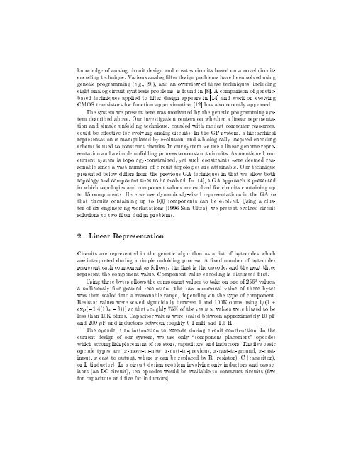
knowledge of analog circuit design and creates circuits based on a novel circuitencodingtechnique. Various analog lter design problems have been solved <strong>using</strong>genetic programming (e.g., [9]), and an overview of these techniques, includingeight analog circuit synthesis problems, is found in [8]. A comparison of geneticbasedtechniques applied to lter design appears in [14] and work on evolvingCMOS transistors for function approximation [12] has also recently appeared.The system we present here was motivated by the genetic programming systemdescribed above. Our investigation centers on whether a linear representationand simple unfolding technique, coupled with modest computer resources,could be eective for evolving analog circuits. In the GP system, a hierarchicalrepresentation is manipulated by evolution, and a biologically-inspired encodingscheme is used to construct circuits. In our system we use a linear genome representationand a simple unfolding process to construct circuits. As mentioned, ourcurrent system is topology-constrained, yet such constraints were deemed reasonablesince a vast number of circuit topologies are attainable. Our techniquepresented below diers from the previous GA techniques in that we allow bothtopology and component sizes to be evolved. In [14], a GA approach is presentedin which topologies and component values are evolved for circuits containing upto 15 components. Here we use dynamically-sized representations in the GA sothat circuits containing up to 100 components can be evolved. Using a clusterof six engineering workstations (1996 Sun Ultra), we present evolved circuitsolutions to two lter design problems.2 <strong>Linear</strong> <strong>Representation</strong><strong>Circuit</strong>s are represented in the genetic algorithm as a list of bytecodes whichare interpreted during a simple unfolding process. A xed numberofbytecodesrepresent each component as follows: the rst is the opcode, and the next threerepresent the component value. Component value encoding is discussed rst.Using three bytes allows the component values to take on one of 256 3 values,a suciently ne-grained resolution. The raw numerical value of these byteswas then scaled into a reasonable range, depending on the type of component.Resistor values were scaled sigmoidally between 1 and 100K ohms <strong>using</strong> 1=(1 +exp(,1:4(10x,8))) so that roughly 75% of the resistor values were biased to beless than 10K ohms. Capacitor values were scaled between approximately 10 pFand 200 F and inductors between roughly 0.1 mH and 1.5 H.The opcode is an instruction to execute during circuit construction. In thecurrent design of our system, we use only \component placement" opcodeswhich accomplish placement of resistors, capacitors, and inductors. The ve basicopcode types are: x-move-to-new, x-cast-to-previous, x-cast-to-ground, x-castinput,x-cast-to-output, where x can be replaced by R (resistor), C (capacitor),or L (inductor). In a circuit design problem involving only inductors and capacitors(an LC circuit), ten opcodes would be available to construct circuits (vefor capacitors and ve for inductors).