Automated Analog Circuit Synthesis using a Linear Representation
Automated Analog Circuit Synthesis using a Linear Representation
Automated Analog Circuit Synthesis using a Linear Representation

Create successful ePaper yourself
Turn your PDF publications into a flip-book with our unique Google optimized e-Paper software.
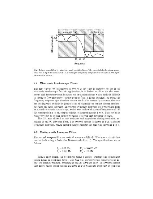
passbandstopbandattenuation (dB)KpKsfp fc fsfrequencyFig. 3. Low-pass lter terminology and specications. The crosshatched regions representout-of-specication areas. An example frequency response curve that meets specicationsis shown.4.1 Electronic Stethoscope <strong>Circuit</strong>The rst circuit we attempted to evolve is one that is suitable for use in anelectronic stethoscope. In this application, it is desired to lter out the extraneoushigh-frequency sounds picked up by a microphone which make it dicultto listen to (low-frequency) bodily sounds (e.g., a heart beating). As such, thefrequency response specications do not need to be extremely accurate since weare dealing with audible frequencies and the human ear cannot discern frequenciesthat are close together. The target frequency response data was taken froman actual electronic stethoscope, which was built with a cuto frequency of 796Hz corresponding to an output voltage of approximately 1 volt. This circuit isrelatively easy to design and so we chose it as our rst problem to solve.The GA was allowed to use resistors and capacitors during evolution, resultingin an RC low-pass lter. The evolved circuit is shown in Fig. 4 and itsfrequency response, which matches almost exactly the target is shown in Fig. 5.4.2 Butterworth Low-pass FilterThe second low-pass lter we evolved was more dicult. We chose a circuit thatcan be built <strong>using</strong> a 3rd-order Butterworth lter [7]. The specications are asfollows:f p = 925 Hz K p =3:0103 dBf s = 3200 Hz K s =22dBSuch a lter design can be derived <strong>using</strong> a ladder structure and componentvalues found in published tables. The GA was allowed to use capacitors and inductorsduring evolution, resulting in an LC low-pass lter. The evolved circuitthat meets these specications is shown in Fig. 6 and its frequency response is