InPro 7000-VP Series Instruction manual ... - Mettler Toledo
InPro 7000-VP Series Instruction manual ... - Mettler Toledo
InPro 7000-VP Series Instruction manual ... - Mettler Toledo

Create successful ePaper yourself
Turn your PDF publications into a flip-book with our unique Google optimized e-Paper software.
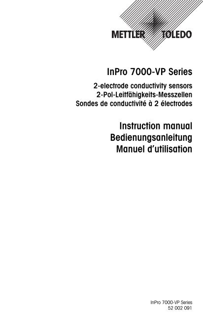
<strong>InPro</strong> <strong>7000</strong>-<strong>VP</strong> <strong>Series</strong>2-electrode conductivity sensors2-Pol-Leitfähigkeits-MesszellenSondes de conductivité à 2 électrodes<strong>Instruction</strong> <strong>manual</strong>BedienungsanleitungManuel d’utilisation<strong>InPro</strong> <strong>7000</strong>-<strong>VP</strong> <strong>Series</strong>52 002 091
English Page 3Deutsch Seite 21Français Page 39
<strong>InPro</strong> <strong>7000</strong>-<strong>VP</strong> <strong>Series</strong> 3<strong>InPro</strong> <strong>7000</strong>-<strong>VP</strong> <strong>Series</strong>2-electrode conductivity sensors<strong>Instruction</strong> <strong>manual</strong>Subject to technical changes without prior notice.© It is strictly forbidden to reprint this instruction <strong>manual</strong> or any parts thereof withoutthe written permission of <strong>Mettler</strong>-<strong>Toledo</strong> AG, Process Analytics, Im Hackacker 15,8902 Urdorf, Switzerland. No section or excerpt whatsoever may be reproduced or withthe assistance of electronic systems be edited, duplicated or distributed, in particular inthe form of photocopies, photographs, magnetic media or other recording methods. Allrights reserved, especially the right of duplication and translation as well as in regardto patent and registration rights.<strong>Mettler</strong>-<strong>Toledo</strong> GmbH, 8606 Greifensee, Switzerland© 07 / 12 <strong>Mettler</strong>-<strong>Toledo</strong> AG, CH - 8606 Greifensee <strong>InPro</strong> <strong>7000</strong>-<strong>VP</strong> <strong>Series</strong>Printed in USA 52 002 091
4 <strong>InPro</strong> <strong>7000</strong>-<strong>VP</strong> <strong>Series</strong>Contents1 Product description 51.1 Introduction 51.2 Equipment and scope of delivery 51.3 Technical data 62 Safety 72.1 Application compatibility 72.2 Proper utilization 82.3 Safety measures 82.4 Use in Ex-zones 93 Initial start-up 133.1 Installation 133.2 Electrical connections 144 Maintenance and troubleshooting 164.1 Conditions of warranty 164.2 Maintenance 164.3 Troubleshooting 175 Removal from operation, storage, disposal 175.1 Removal from operation 175.2 Storage 185.3 Disposal 186 Dimensional drawings 187 Accessories 20<strong>InPro</strong> <strong>7000</strong>-<strong>VP</strong> <strong>Series</strong>© 07 / 12 <strong>Mettler</strong>-<strong>Toledo</strong> AG, CH - 8606 Greifensee52 002 091 Printed in USA
<strong>InPro</strong> <strong>7000</strong>-<strong>VP</strong> <strong>Series</strong> 51 Product description1.1 IntroductionConformity<strong>InPro</strong> <strong>7000</strong>-<strong>VP</strong> <strong>Series</strong> 2-electrode sensors are in conformance with the followingregulations (exceptions are described in section 1.3):Low voltage – EU Guidelines 2006/95/ECguidelines: – Swiss Guidelines SR 734.26 NEV– Safety Guidelines EN61010-1– IP protection rating EN60529 IP68 (<strong>VP</strong> connector)EMC Guidelines:– EU Guidelines 2004/108/EC– Swiss Guidelines SR 734.5 VEMV– Emission EN55022– Immunity EN55024Explosion protection– 94/9/EG– SNCH 04 ATEX 3637 X– L-5201 Sandweiler, SNCH 0499CertificatesCE, Quality, Material Certificate following EN 10204 (3.1B) for sensor with316L SS electrodes, ATEX EU Guideline 94 /9/EWG.MarkingsThe markings labeled on each sensor state the following information:METTLER TOLEDOCH-8902 Urdorf<strong>InPro</strong>700x-<strong>VP</strong>II 1/2 G Ex ia IIC T3/T4/T5/T6Cell M: XXXXXX Temp. M: XXXXXX see instruction <strong>manual</strong>Serial No: XXXXXXXXX Order No: XXXXXXXX SNCH 04 ATEX 3637 X1.2 Equipment and scope of deliveryScope of deliveryThe <strong>InPro</strong> <strong>7000</strong>-<strong>VP</strong> <strong>Series</strong> sensors are delivered ready for use. Each sensoris accompanied by this instruction <strong>manual</strong>, an individual «Certificateof Quality» and a Material Certificate following EN 10204 (exceptions:<strong>InPro</strong> <strong>7000</strong>-<strong>VP</strong> and <strong>InPro</strong> 7005-<strong>VP</strong>). Other Certificates may be included as0499© 07 / 12 <strong>Mettler</strong>-<strong>Toledo</strong> AG, CH - 8606 Greifensee <strong>InPro</strong> <strong>7000</strong>-<strong>VP</strong> <strong>Series</strong>Printed in USA 52 002 091
6 <strong>InPro</strong> <strong>7000</strong>-<strong>VP</strong> <strong>Series</strong>specified for the individual product. Please check that the details given inthe Certificate of Quality match the sensor label. For each sensor, the relevantcell constant has been determined individually in an ultrapure watersystem at 25 °C (77 °F) during the manufacturing process, and the valuedocumented in the accompanying «Certificate of Quality».It is not necessaryto re-calibrate the sensor before initial operation.PackagingThe packaging consists of cardboard and plastic material.Keep the packaging for later use during storage or transportation of the sensor.Should you wish to dispose of the packaging material, pleaseobserve your local regulations as well as those data and instructions givenin Chapter 5.3 of this <strong>manual</strong>.Unpacking and inspectionPlease check the sensors immediately during unpacking in order to determinepossible damage or missing items. Any irregularities should immediatelybe reported to your carrier and to your supplier.1.3 Technical dataTechnical data <strong>InPro</strong> <strong>7000</strong>-<strong>VP</strong> <strong>InPro</strong> 7001-<strong>VP</strong> <strong>InPro</strong> 7002-<strong>VP</strong> <strong>InPro</strong> 7005-<strong>VP</strong>Wetted Titanium, PEEK, 316L SS 316L SS, Titanium, PEEK,materials PVDF, Viton (1.4435), (1.4435), Viton, PTFE-PEEK, Viton PEEK coated 316 SSTemperature –10...100 °C –10...100 °C –10...120 °C –10...100 °Crange (14...212 °F) (14...212 °F) (14...248 °F) (14...212 °F)Process adaption/ 3/4" NPT PG 13.5 Tri-Clamp 3/4" NPTconnection 1" NPT conduit (1.5" & 2")TuchenhagenVarivent(DN 40-DN 125)Max. pressure 34 bar 17 bar 31 bar 17 barat 25 °C (77 °F) (500 psi) (250 psi) (450 psi) (250 psi)Sterilizability Non-sterilizable max. 131 °C max. 150 °C Non-sterilizable(max. 268 °F) (max. 312 °F)Protection class IP68 IP68 IP68 IP68(<strong>VP</strong> connector)(sensor: IP65)<strong>InPro</strong> <strong>7000</strong>-<strong>VP</strong> <strong>Series</strong>© 07 / 12 <strong>Mettler</strong>-<strong>Toledo</strong> AG, CH - 8606 Greifensee52 002 091 Printed in USA
<strong>InPro</strong> <strong>7000</strong>-<strong>VP</strong> <strong>Series</strong> 7Each <strong>InPro</strong> <strong>7000</strong>-<strong>VP</strong> <strong>Series</strong> sensor is equipped with an integral temperatureprobe Pt1000, IEC 751 Class A.The nominal cell constant is 0.1 cm -1 . The exact value is printed on thesensor label.For each sensor, the cell constant and temperature constant have been measured/establishedindividually and the values documented in the accompanyingQuality Certificate. All calibrations can be traced back to NIST and/orASTM Standards.Both the measuring range and the system measurement accuracy stronglydepend upon which type of transmitter is employed.Subject to technical changesTransmitter 7220 X M 700 Cond 7100 e Cond 7050 eSensor<strong>InPro</strong> <strong>7000</strong>/7005 7 9 9 4<strong>InPro</strong> 7001 4 5 5 2<strong>InPro</strong> 7002 5 7 7 31 0.01–120 µS/cm 4 0.02– 200 µS/cm 7 0.02–1.2000µ S/cm2 0.02– 50 µS/cm 5 0.02– 500 µS/cm 8 0.02–1.2500µ S/cm3 0.02–100 µS/cm 6 0.02–1000µ S/cm 9 0.02–10.000µ S/cm2 Safety2.1 Application compatibilityThe wetted material parts of the sensor (several different materials comeinto contact with the sample medium) can under some circumstance beincompatible with the particular composition of the process medium and/orof the operating conditions. Responsibility to verify application compatibilitylies wholly with the user.The compatibility of different types of material are outlined onhttp://www.coleparmer.com/techinfo/chemcomp.asp.<strong>Mettler</strong>-<strong>Toledo</strong> GmbH, Process Analytics accepts no responsibility whatsoeverfor the correctness or accuracy of such details.© 07 / 12 <strong>Mettler</strong>-<strong>Toledo</strong> AG, CH - 8606 Greifensee <strong>InPro</strong> <strong>7000</strong>-<strong>VP</strong> <strong>Series</strong>Printed in USA 52 002 091
8 <strong>InPro</strong> <strong>7000</strong>-<strong>VP</strong> <strong>Series</strong>2.2 Proper utilizationMETTLER TOLEDO <strong>InPro</strong> <strong>7000</strong>-<strong>VP</strong> <strong>Series</strong> sensors are intended solely for theprecise measurement of conductivity in aqueous and some limited nonaqueoussolutions in industrial applications.Any other use, or any operation over and above that intended by themanufacturer, are not recommended and can lead to harm or injury tomaterial/equipment and persons. This is also relevant for applications whichdo not comply with the technical data labeled on the sensor. For anydamage arising from such misuse, the user assumes full and soleresponsibility.2.3 Safety measuresThe <strong>InPro</strong> <strong>7000</strong>-<strong>VP</strong> <strong>Series</strong> sensors have been manufactured in line withstate-of-the-art technology and in accordance with accepted technicalsafety regulations. Nevertheless, the sensors can still represent a source ofrisk and danger:– if the sensors are operated by insufficiently trained personnel,– if the sensors are employed incorrectly or not as intended by themanufacturer,– if the sensors are not regularly maintained or serviced.Local legislation and regulations must be observed at all times. Suchstipulations do not form an integral part of this instruction <strong>manual</strong>.It is necessary to use protective gear, including gloves, for persons comingin contact with the fluid. It is recommended to use gloves when handlingthe electrodes of the sensor to limit contamination of the sensor.The user is responsible for the instruction and training of personnel. Additionalcopies of the instruction <strong>manual</strong> can be ordered from your supplier.This instruction <strong>manual</strong> is an essential element of the sensor equipmentand must at all times be readily available to operators directly at the measurementsite.Before the sensor is removed from the process/process adapter, it must beensured that the process pressure has been reduced to a safe level and theprocess temperature lowered to a safe range. Any escape of hot process<strong>InPro</strong> <strong>7000</strong>-<strong>VP</strong> <strong>Series</strong>© 07 / 12 <strong>Mettler</strong>-<strong>Toledo</strong> AG, CH - 8606 Greifensee52 002 091 Printed in USA
<strong>InPro</strong> <strong>7000</strong>-<strong>VP</strong> <strong>Series</strong> 9fluid under pressure can cause damage to material/equipment or injury topersons.No modification whatsoever may be carried out on the sensors. Anyunauthorized modification or manipulation of the sensors results in immediateexpiration of the full scope of warranty granted by the manufacturer.2.4 Use in Ex-zonesNote!For intended installation in an Ex-classified area, please observe the followingguidelines:Ex-classification:II 1/2 G Ex ia IIB T3 / T4 / T5 / T6 (for sensors with polymer body)resp.II 1/2 G Ex ia IIC T3 / T4 / T5 / T6 (for sensors made of stainlesssteel or stainless steel coated with PTFE)Marking and number of the test certificate:SNCH 04 ATEX 3637 XEx-classification II 1/2 G Ex ia IIB T3 / T4 / T5 / T6resp. II 1/2 G Ex ia IIC T3 / T4 / T5 / T6 in accordance with EC TypeExamination Certification SNCH 04 ATEX 3637 XIntroductionThe conductivity sensors with polymer body are in accordance withRL 94/9/EC (ATEX 95) Appendix 1 classified as plant equipment in theEquipment Group II Category 1/2G which in accordance with RL 99/92/EC(ATEX 137) may be employed in the Zones 0/1 or 0/2 or 1/2 as well as inGas Groups IIA and IIB, areas in which there is potential risk of explosionof inflammable materials in the Temperature Classes T1 to T6.The conductivity sensors made of stainless steel or of stainless steelcoated with PTFE coating are in accordance with RL 94/9/EC (ATEX 95)Appendix 1 classified as plant equipment in the Equipment Group II Category1/2G which in accordance with RL 99/92/EC (ATEX 137) may be© 07 / 12 <strong>Mettler</strong>-<strong>Toledo</strong> AG, CH - 8606 Greifensee <strong>InPro</strong> <strong>7000</strong>-<strong>VP</strong> <strong>Series</strong>Printed in USA 52 002 091
10 <strong>InPro</strong> <strong>7000</strong>-<strong>VP</strong> <strong>Series</strong>employed in the Zones 0/1 or 0/2 or 1/2 as well as in Gas Groups IIA, IIBand IIC, areas in which there is potential risk of explosion of inflammablematerials in the Temperature Classes T1 to T6.During installation and use of the equipment, the requirements of EN 60079-14 are to be fully complied with.Rated dataLF measuring circuit andtemperature measuring circuitIntrinsically safe explosion protectionclass Ex ia IIConly for connection to a certified intrinsicallysafe circuit.Maximum values:U i ≤16 VI i ≤190 mAP i ≤200 mWThe effective internal inductances andcapacitances are negligibly small.The above values always apply to the sum of all internal circuits of the associatedintrinsically safe supply and evaluation device.<strong>InPro</strong> <strong>7000</strong>-<strong>VP</strong> <strong>Series</strong>© 07 / 12 <strong>Mettler</strong>-<strong>Toledo</strong> AG, CH - 8606 Greifensee52 002 091 Printed in USA
<strong>InPro</strong> <strong>7000</strong>-<strong>VP</strong> <strong>Series</strong> 11Special conditions X1. The relationship between the maximum allowable ambient or mediumtemperature and the temperature class is shown in the following table:For Ui ≤ 16 V, Ii ≤ 190 mA, Pi ≤ 200 mW.LF measuring circuit and temperature measuring circuits:Temperature ClassT6T5T4T3Max. ambient resp.medium temperature51 °C63 °C91 °C143 °C2. The measuring systems drawings must be followed for installation.3. The capacitance and inductance of the connecting cable must be takeninto account for the layout.4. The metal body of the conductivity sensor or the safety weld-in sockets orthe METTLER TOLEDO housing type InFit 76*-*** resp. InTrac 7**-***must be electrically connected to the main potential equalization systemof the plant (grounded).5. The metal body of the conductivity sensor or the safety weld-in sockets orthe METTLER TOLEDO housing type InFit 76*-*** resp. InTrac 7**-***are, if necessary, to be included into the recurring pressure test of theunit.© 07 / 12 <strong>Mettler</strong>-<strong>Toledo</strong> AG, CH - 8606 Greifensee <strong>InPro</strong> <strong>7000</strong>-<strong>VP</strong> <strong>Series</strong>Printed in USA 52 002 091
12 <strong>InPro</strong> <strong>7000</strong>-<strong>VP</strong> <strong>Series</strong>Declaration of conformity<strong>InPro</strong> <strong>7000</strong>-<strong>VP</strong> <strong>Series</strong>© 07 / 12 <strong>Mettler</strong>-<strong>Toledo</strong> AG, CH - 8606 Greifensee52 002 091 Printed in USA
<strong>InPro</strong> <strong>7000</strong>-<strong>VP</strong> <strong>Series</strong> 133 Initial start-up3.1 InstallationThe sensors are to be mounted in such a way that the sample mediumflows directly into the sensor through the orifice at the tip and re-emergesthrough the vent holes. Any other installation position of the sensors cancreate the risk of formation of airlocks, or of contamination through depositsof solid matter.Luft wird im Sensor eingeschlossen30º 30ºSchlamm wird imSensor eingeschlossenSensororientierungFlussrichtungFlussrichtungEntlüftungsöffnungT-StückOrientierung in Probenmit niedriger GeschwindigkeitSensorFlow of sample medium must be toward the face of the sensor. Air bubblesand solid matter deposits are to be avoided. A minimum clearance of 0.6cm ( 1 /4") between sensor and pipe wall must be maintained at the tip ofthe sensor.Vertical mounting (top entry) in a pipe is recommended only if the pipe isfull and no air bubbles are able to develop in the flow.In the event of side mounting (side entry) of the sensor, vertical upwardflow of sample process medium must be ensured.© 07 / 12 <strong>Mettler</strong>-<strong>Toledo</strong> AG, CH - 8606 Greifensee <strong>InPro</strong> <strong>7000</strong>-<strong>VP</strong> <strong>Series</strong>Printed in USA 52 002 091
14 <strong>InPro</strong> <strong>7000</strong>-<strong>VP</strong> <strong>Series</strong>3.2 Electrical connectionsAll of the <strong>InPro</strong> <strong>7000</strong>-<strong>VP</strong> <strong>Series</strong> sensors can be connected to the associatedtransmitter using the appropriate multiwire cable from METTLER TOLEDO.Depending on which type of transmitter is employed, not all cable strandsmay have to be used.Colors and function of the cable strands (supplied separately)2-electrode sensor 4-electrode sensor ColorInner electrode Current electrode 1 white/blueVoltage electrode 1 whiteVoltage electrode 2 blueOuter electrode Current electrode 2 blackTemperature probe T1 Temperature probe T1 greenTemperature probe T2 Temperature probe T2 redShielding Shielding transparentConnection to the relative transmitter must be followed according to thewiring diagram below.METTLER TOLEDO supplies the following cablesCable lengthOrder No.11.5 m (5 ft) 58 080 20113.0 m (10 ft) 58 080 20214.6 m (15 ft) 58 080 20317.6 m (25 ft) 58 080 20415.2 m (50 ft) 58 080 20522.9 m (75 ft) 58 080 20630.5 m (100 ft) 58 080 207<strong>InPro</strong> <strong>7000</strong>-<strong>VP</strong> <strong>Series</strong>© 07 / 12 <strong>Mettler</strong>-<strong>Toledo</strong> AG, CH - 8606 Greifensee52 002 091 Printed in USA
<strong>InPro</strong> <strong>7000</strong>-<strong>VP</strong> <strong>Series</strong> 15Wiring diagramTransmitter Cond 7050 e Cond 7050 e Cond 7100 e Cond 7100 e/2(X)H Cond 7100 PAmodel panel mount wall mount (4-wire unit) (2-wire unit) Cond 7100 e FFwire colorwhite/blue 15 30 1 1 1transparent not used not used C 5 5white 16 31 2 2 2green 25 27 E 8 8red 24 26 D 7 7black 18 33 4 4 4blue 17 32 3 3 3shield 22 21 5 5 5Instrument Jumper JumperTerminal 25–26 27–28jumperTransmitter model 7220 X (2-wire unit) M 700 (X) (4-wire unit)wire colorwhite/blue 1 1transparent 5 16white 2 2green 8 18red 6 17black 4 4blue 3 3shield 5 5Instrument Jumper 7–8 Jumper 18–19Terminaljumper2-wire = two-wire, loop-powered transmitter4-wire = four-wire, mains-powered transmitter© 07 / 12 <strong>Mettler</strong>-<strong>Toledo</strong> AG, CH - 8606 Greifensee <strong>InPro</strong> <strong>7000</strong>-<strong>VP</strong> <strong>Series</strong>Printed in USA 52 002 091
16 <strong>InPro</strong> <strong>7000</strong>-<strong>VP</strong> <strong>Series</strong>4 Maintenance and troubleshooting4.1 Conditions of warrantyMETTLER TOLEDO guarantees the quality of materials and workmanshipwithin a narrow range of manufacturing tolerances, so that the productpurchased is free from any substantial deviations from material andmanufacturing quality standards. The warranty is valid for a period of oneyear from date of delivery: If within this warranty period, any repair orreplacement should become necessary, and such cause is not due tomisuse or incorrect application, please return the sensor, freight pre-paid,to your appropriate METTLER TOLEDO supplier. Repair work will be carriedout free of charge. Final decision on whether the defect is due to a manufacturingerror or to incorrect operation of the sensor by the customeris made at the option of the Customer Service department of METTLERTOLEDO. After expiration of the warranty period, sensors will be repaired orreplaced on an exchange basis against payment of the costs involved.4.2 MaintenanceDirty or contaminated sensors can deliver incorrect measurement values.If fouling is presumed, the sensor is to be removed from operation and theelectrodes as well as the insulation between the electrodes cleaned witha soft cloth. Suitable cleaning solutions are mild detergents or dilutedacids (< 0.5 % by wt.) such as hydrochloric or nitric acid. Never use cleaningagents that are not compatible with the material to be cleaned.When handling acids, precautionary measures are to be taken.The sensor must be thoroughly flushed with distilled or deionized waterprior to re-installation.Following cleaning and re-installation into the process, it can take fromseveral minutes up to several hours until the sensor delivers the originallymeasured value.<strong>InPro</strong> <strong>7000</strong>-<strong>VP</strong> <strong>Series</strong>© 07 / 12 <strong>Mettler</strong>-<strong>Toledo</strong> AG, CH - 8606 Greifensee52 002 091 Printed in USA
<strong>InPro</strong> <strong>7000</strong>-<strong>VP</strong> <strong>Series</strong> 174.3 TroubleshootingError Possible cause Corrective actionNo signal on display Electrical connections Check all connectionseither missing orand associated cablingincorrectly in place.Sensor is not in contactCheck installationwith the sample mediumfor air pocketsNo temperature signal Temperature probe is Check all connectionsnot connectedand associated cablingTransmitter does not support Replacement of transmitterPt1000 RTDor sensor necessaryIncorrect or unstable Sensor is contaminated/ Clean the sensormeasurement reading fouled (electrodes)Sensor is installed tooEnsure minimum distanceclose to pipe wallof 0.6 cm ( 1 /4") betweensensor tip and pipe wallis maintained5 Removal from operation, storage, disposal5.1 Removal from operationThe sensor is only conditionally subject to aging. When used as intendedand appropriately maintained and serviced, the lifetime of the sensor canextend to several years.Before removing the sensor from the process/process adapter, it must beensured that the process pressure has been reduced to a safe level andthe process temperature has lowered to a safe range. Any escape of hotprocess medium under pressure can cause damage to material/equipmentor injury to persons.After removal from the process the sensor should first be flushed withdistilled water.If the sensor incurs a defect, it can not be repaired and must be disposedunder observance of prevailing local regulations.© 07 / 12 <strong>Mettler</strong>-<strong>Toledo</strong> AG, CH - 8606 Greifensee <strong>InPro</strong> <strong>7000</strong>-<strong>VP</strong> <strong>Series</strong>Printed in USA 52 002 091
18 <strong>InPro</strong> <strong>7000</strong>-<strong>VP</strong> <strong>Series</strong>5.2 StorageIf the sensor is not use, it can be stored dry. However, it has to be reconditionedin the process fluid accordingly prior to renewed operation. Thisprocedure may take several hours to complete.5.3 DisposalDisposal is to be carried out by the user in accordance with valid localregulations.The packaging consists of:– cardboard– plastic filmThe sensor is of:– medium-wetted materials according to the specifications of the sensor– electronics material (cable, components)– PEEK (plug)6 Dimensional drawings<strong>InPro</strong> <strong>7000</strong>-<strong>VP</strong><strong>InPro</strong> 7005-<strong>VP</strong>63525.045718.0153.26.0382.33.2429.21.1534.01.35752.97cminch12.7.50012.7.500<strong>InPro</strong> <strong>7000</strong>-<strong>VP</strong> <strong>Series</strong>© 07 / 12 <strong>Mettler</strong>-<strong>Toledo</strong> AG, CH - 8606 Greifensee52 002 091 Printed in USA
<strong>InPro</strong> <strong>7000</strong>-<strong>VP</strong> <strong>Series</strong> 19<strong>InPro</strong> 7001-<strong>VP</strong> 3.1B74.092.917a = Length<strong>InPro</strong> 7001/120-<strong>VP</strong> 120 (4.73)<strong>InPro</strong> 7001/225-<strong>VP</strong> 225 (8.86)10.41.410<strong>InPro</strong> 7002-TC-<strong>VP</strong> 3.1B <strong>InPro</strong> 7002-VAR-<strong>VP</strong> 3.1B2.5564.853.3183.995200285764.52.544.43112.596.35.250R.25 [R6.35]1.4035.44.6215.7515.9.625a = Length<strong>InPro</strong> 7002/1.5" TC-<strong>VP</strong> 85.1 (3.35)<strong>InPro</strong> 7002/2" TC-<strong>VP</strong> 104.1 (4.10)<strong>InPro</strong> 7002-VAR-<strong>VP</strong> 35.44 (1.40)© 07 / 12 <strong>Mettler</strong>-<strong>Toledo</strong> AG, CH - 8606 Greifensee <strong>InPro</strong> <strong>7000</strong>-<strong>VP</strong> <strong>Series</strong>Printed in USA 52 002 091
20 <strong>InPro</strong> <strong>7000</strong>-<strong>VP</strong> <strong>Series</strong>7 AccessoriesO-ringsSensor Standard O-ring Complementary O-rings Order No.<strong>InPro</strong> 7001/120-<strong>VP</strong> 3.1B Viton FDA 20 302 1000<strong>InPro</strong> 7001/225-<strong>VP</strong> 3.1B (10.77 x 2.62)CableCable lengthOrder No.11.5 m (5 ft) 58 080 20113.0 m (10 ft) 58 080 20214.6 m (15 ft) 58 080 20317.6 m (25 ft) 58 080 20415.2 m (50 ft) 58 080 20522.9 m (75 ft) 58 080 20630.5 m (100 ft) 58 080 207The max. cable length recommended is 60 m.Cable adapter from <strong>VP</strong> (male) to Conxal (female)Designation Cable length Order No.<strong>VP</strong> cable adapter 0.9 m (3 ft) 58 080 101Housings for <strong>InPro</strong> <strong>7000</strong>-<strong>VP</strong> <strong>Series</strong>Silicon FDA (10.77 x 2.62) 20 301 1136Kalrez (10.78 x 2.62) 20 304 1000Kalrez FDA (10.78 x 2.62) 20 304 1034EPDM FDA (10.77 x 2.62) 20 303 1206Designation Applied as Suitable sensorInFit 761 e Stationary housing <strong>InPro</strong> 7001/120 and 225-<strong>VP</strong>InFit 762 e Stationary housing <strong>InPro</strong> 7001/120-<strong>VP</strong>InFit 777 e Rectractable housing <strong>InPro</strong> 7001/225-<strong>VP</strong>InFit 787 e Rectractable housing <strong>InPro</strong> 7001/120-<strong>VP</strong>InFit 798 e Rectractable housing <strong>InPro</strong> 7001/120-<strong>VP</strong>InDip 550 Immersion housing <strong>InPro</strong> <strong>7000</strong>-<strong>VP</strong>/<strong>InPro</strong> 7005-<strong>VP</strong><strong>InPro</strong> <strong>7000</strong>-<strong>VP</strong> <strong>Series</strong>© 07 / 12 <strong>Mettler</strong>-<strong>Toledo</strong> AG, CH - 8606 Greifensee52 002 091 Printed in USA
<strong>InPro</strong> <strong>7000</strong>-<strong>VP</strong> <strong>Series</strong> 21<strong>InPro</strong> <strong>7000</strong>-<strong>VP</strong> Serie2-Pol-Leitfähigkeits-MesszellenBedienungsanleitungTechnische Änderungen ohne vorherige Anzeige sind vorbehalten.© Der Nachdruck dieser Bedienungsanleitung, auch auszugsweise, ist verboten.Ohne schriftliche Bewilligung der Firma <strong>Mettler</strong>-<strong>Toledo</strong> GmbH, Process Analytics, IndustrieNord, CH - 8902 Urdorf, dürfen keine Teile davon in irgendeiner Form reproduziertoder unter Anwendung elektronischer Systeme, insbesondere in Form von Fotokopien,Magnetverfahren oder anderen Aufzeichnungsarten, verarbeitet, vervielfältigt oderverbreitet werden. Alle Rechte, insbesondere das Recht der Vervielfältigung und Übersetzungsowie Patent- oder Registrierungsrechte, sind vorbehalten.<strong>Mettler</strong>-<strong>Toledo</strong> GmbH, CH - 8606 Greifensee© 07 / 12 <strong>Mettler</strong>-<strong>Toledo</strong> AG, CH - 8606 Greifensee <strong>InPro</strong> <strong>7000</strong>-<strong>VP</strong> <strong>Series</strong>Printed in USA 52 002 091
22 <strong>InPro</strong> <strong>7000</strong>-<strong>VP</strong> <strong>Series</strong>Inhaltsverzeichnis1 Produktebeschreibung 231.1 Einleitung 231.2 Ausstattung und Lieferumfang 231.3 Technische Daten 242 Sicherheit 252.1 Anwendungskompatibilität 252.2 Bestimmungsgemässe Verwendung 262.3 Sicherheitsmassnahmen 262.4 Einsatz im Ex-Bereich 273 Inbetriebnahme 313.1 Montage 313.2 Elektrische Anschlüsse 324 Wartung und Störungsbehebung 344.1 Garantiebestimmungen 344.2 Wartung 344.3 Störungsbehebung 355 Ausserbetriebsetzung, Lagerung, Entsorgung 355.1 Ausserbetriebsetzung 355.2 Lagerung 355.3 Entsorgung 366 Masszeichnungen 367 Zubehör 38<strong>InPro</strong> <strong>7000</strong>-<strong>VP</strong> <strong>Series</strong>© 07 / 12 <strong>Mettler</strong>-<strong>Toledo</strong> AG, CH - 8606 Greifensee52 002 091 Printed in USA
<strong>InPro</strong> <strong>7000</strong>-<strong>VP</strong> <strong>Series</strong> 231 Produktebeschreibung1.1 EinleitungKonformität2-Pol-Messzellen der <strong>InPro</strong> <strong>7000</strong>-<strong>VP</strong> Serie entsprechen folgenden Bestimmungen(Ausnahme siehe 1.3):Niederspannungs- – EU Richtlinie 2006/95/EGrichtlinien: – Schweizer Richtlinie SR 734.26 NEV– Sicherheitsrichtlinien EN61010-1– IP-Schutzgrad EN60529 IP68 (<strong>VP</strong>-Stecker)EMV Richtlinien: – EU Richtlinie 2004/108/EG– Schweizer Richtlinie SR 734.5 VEMV– Emission EN55022– Immunität EN55024Explosionsschutzrichtlinie– 94/9/EG– SNCH 04 ATEX 3637 X– L-5201 Sandweiler, SNCH 0499ZertifikateCE, Qualität, Materialzertifikat nach EN 10204 (3.1B) für Messzellen mitElektroden aus rostfreiem Stahl, ATEX EU Guideline 94 /9/EWG.KennzeichnungDer Aufdruck auf jeder Messzelle enthält folgende Informationen:METTLER TOLEDOCH-8902 Urdorf<strong>InPro</strong>700x-<strong>VP</strong>II 1/2 G Ex ia IIC T3/T4/T5/T6Cell M: XXXXXX Temp. M: XXXXXX see instruction <strong>manual</strong>Serial No: XXXXXXXXX Order No: XXXXXXXX SNCH 04 ATEX 3637 X04991.2 Ausstattung und LieferumfangLieferumfangDie Messzellen der <strong>InPro</strong> <strong>7000</strong>-<strong>VP</strong> Serie werden gebrauchsfertig geliefert.Jeder Messzelle ist diese Bedienungsanleitung, ein individuelles «Certificateof Quality» sowie ein Materialzertifikat nach EN 10204 beigelegt (Aus-© 07 / 12 <strong>Mettler</strong>-<strong>Toledo</strong> AG, CH - 8606 Greifensee <strong>InPro</strong> <strong>7000</strong>-<strong>VP</strong> <strong>Series</strong>Printed in USA 52 002 091
24 <strong>InPro</strong> <strong>7000</strong>-<strong>VP</strong> <strong>Series</strong>nahme: <strong>InPro</strong> <strong>7000</strong>-<strong>VP</strong> und <strong>InPro</strong> 7005-<strong>VP</strong>). Weitere Zertifikate können derPackung beiliegen. Überprüfen sie die Angaben des Zertifikates mit dem Aufdruckauf der Messzelle. Bei jeder Messzelle wird die Zellkonstante bei derHerstellung in einem Reinstwasserkreislauf bei 25 °C individuell bestimmtund im beigelegten «Certificate of Quality» dokumentiert. Eine erneuteKalibrierung der Messzelle vor der Inbetriebnahme wird nicht empfohlen.VerpackungDie Verpackung besteht aus Karton und PlastikBewahren Sie die Verpackung, für eine spätere Lagerung oder einen Transportder Messzelle, auf. Falls Sie die Verpackung entsorgen wollen, beachtenSie die lokalen Vorschriften sowie Abschnitt 5.3.Kontrolle der LieferungBitte prüfen Sie die Messzelle beim Auspacken auf eventuelle Beschädigungen.Falls Sie solche feststellen, melden Sie dies umgehend dem Transporteurund ihrem Lieferanten.1.3 Technische DatenTechnische Daten <strong>InPro</strong> <strong>7000</strong>-<strong>VP</strong> <strong>InPro</strong> 7001-<strong>VP</strong> <strong>InPro</strong> 7002-<strong>VP</strong> <strong>InPro</strong> 7005-<strong>VP</strong>Benetzte Titan, PEEK, 316L rostfreier 316L rostfreier Titan, PEEK,Werk- PVDF, Viton Stahl (1.4435), Stahl (1.4435), PTFE-beschichterstoffe PEEK, Viton PEEK Stahl 316, VitonTemperaturbereich –10...100 °C –10...100 °C –10...120 °C –10...100 °CProzess- 3/4" NPT PG 13.5 Tri-Clamp 3/4" NPTanschluss 1" NPT conduit (1.5" & 2")TuchenhagenVarivent(DN 40-DN 125)Max. Druck 34 bar 17 bar 31 bar 17 barbei 25 °CSterilisierbarkeit Nicht max. 131 °C max. 150 °C NichtsterilisierbarsterilisierbarSchutzart IP68 IP68 IP68 IP68(<strong>VP</strong>-Stecker)(Sensor: IP65)<strong>InPro</strong> <strong>7000</strong>-<strong>VP</strong> <strong>Series</strong>© 07 / 12 <strong>Mettler</strong>-<strong>Toledo</strong> AG, CH - 8606 Greifensee52 002 091 Printed in USA
<strong>InPro</strong> <strong>7000</strong>-<strong>VP</strong> <strong>Series</strong> 25Alle Messzellen der <strong>InPro</strong> <strong>7000</strong>-<strong>VP</strong> Serie haben einen eingebauten TemperaturfühlerPt1000, IEC 751 Klasse A.Die nominelle Zellkonstante ist 0.1 cm -1 . Der exakte Wert ist auf dem Etikettaufgedruckt.Bei jeder Messzelle wird die Zellkonstante und die Temperaturkonstanteindividuell ausgemessen und im beigelegten Qualitätszertifikat dokumentiert.Alle Kalibrierungen lassen sich auf NIST- und/oder ASTM-Standardszurückführen.Messbereich und Systemmessgenauigkeit hängen stark vom eingesetztenTransmitter ab.Technische Änderungen vorbehaltenTransmitter 7220 X M 700 Cond 7100 e Cond 7050 eSensor<strong>InPro</strong> <strong>7000</strong>/7005 7 9 9 4<strong>InPro</strong> 7001 4 5 5 2<strong>InPro</strong> 7002 5 7 7 31 0.01–120 µS/cm 4 0.02– 200 µS/cm 7 0.02–1.2000µ S/cm2 0.02– 50 µS/cm 5 0.02– 500 µS/cm 8 0.02–1.2500µ S/cm3 0.02–100 µS/cm 6 0.02–1000µ S/cm 9 0.02–10.000µ S/cm2 Sicherheit2.1 AnwendungskompatibilitätDas benetzte Sensormaterial (mehrere Materialien im Kontakt mit demProzessmedium) ist u.U. nicht mit der Prozesszusammensetzung und denBetriebsbedingungen kompatibel. Die Anwendungskompatibilität liegt ganzin der Verantwortung des Bedieners.Unter http://www.coleparmer.com/techinfo/chemcomp.asp können verschiedeneMaterialkompatibiltäten nachgeschaut werden. Für die Richtigkeitder gemachten Angaben kann <strong>Mettler</strong>-<strong>Toledo</strong> GmbH, Process Analyticskeine Verantwortung übernehmen.© 07 / 12 <strong>Mettler</strong>-<strong>Toledo</strong> AG, CH - 8606 Greifensee <strong>InPro</strong> <strong>7000</strong>-<strong>VP</strong> <strong>Series</strong>Printed in USA 52 002 091
26 <strong>InPro</strong> <strong>7000</strong>-<strong>VP</strong> <strong>Series</strong>2.2 Bestimmungsgemässe VerwendungDie METTLER TOLEDO <strong>InPro</strong> <strong>7000</strong>-<strong>VP</strong> Serie Messzellen sind für die präziseLeitfähigkeitsmessungen in wässrigen oder teilweise wässrigen Lösungenin industriellen Anwendungen bestimmt.Jede andere oder darüber hinausgehende Verwendung gilt als nicht bestimmungsgemässmissbräuchlich und kann zur Gefährdung von Personenoder zu Materialschäden führen. Dies gilt auch für Anwendungen, dienicht den technischen Daten entsprechen. Für allfällige Schäden, die aufeinen solche Verwendung zurückzuführen sind, trägt der Anwender dasalleinige Risiko.2.3 SicherheitsmassnahmenDie Messzellen <strong>InPro</strong> <strong>7000</strong>-<strong>VP</strong> Serie sind nach dem Stand der Technik undden anerkannten sicherheitstechnischen Regeln gebaut. Dennoch könnenvon den Messzellen Risiken und Gefahren ausgehen:– wenn die Messzellen von ungenügend ausgebildeten Personen bedientwerden,– wenn die Messzellen nicht bestimmungsgemäss verwendet werden,– wenn die Messzellen nicht regelmässig gewartet werden.Die lokalen Gesetze und Vorschriften müssen immer beachtet werden. Siesind nicht Bestandteil dieser Bedienungsanleitung.Das Tragen von persönlicher Schutzausrüstung wie Schutzbrille und Schutzkleidungist grundsätzlich dann erforderlich, wenn das Risiko besteht, mitder Prozessflüssigkeit in Berührung zu geraten. Zur Verhinderung von Verschmutzungender Elektrodenoberfläche wird empfohlen, Handschuhe zutragen.Der Betreiber ist für die Instruktion des Personals verantwortlich. Dazu kanndiese Betriebsanleitung auch nachbestellt werden. Diese Betriebsanleitungmuss als Bestandteil der Messzellen jederzeit dem Bedienungspersonal amEinsatzort der Messzelle zur Verfügung stehen.Vor dem Entfernen der Messzelle muss sichergestellt sein, dass der Prozessdruckreduziert und die Prozesstemperatur auf einen sicheren Bereichabgesenkt ist. Heisse, unter Druck austretende Prozessflüssigkeit kann zuSchäden an Material und zur Gefährdung von Personen führen.<strong>InPro</strong> <strong>7000</strong>-<strong>VP</strong> <strong>Series</strong>© 07 / 12 <strong>Mettler</strong>-<strong>Toledo</strong> AG, CH - 8606 Greifensee52 002 091 Printed in USA
<strong>InPro</strong> <strong>7000</strong>-<strong>VP</strong> <strong>Series</strong> 27An der Messzelle dürfen keine Modifikationen vorgenommen werden. Durchnichtautorisierte Modifikationen erlischt jegliche Gewährleistung.2.4 Einsatz im Ex-BereichHinweis!Für die Installation im Ex-Bereich beachten Sie bitte die nachfolgenden Richtlinien:Ex-Klassifikation:II 1/2 G Ex ia IIB T3 / T4 / T5 / T6 (Für Sensoren aus Kunststoff)bzw.II 1/2 G Ex ia IIC T3 / T4 / T5 / T6 (Für Sensoren aus Metall bzw.für Sensoren aus Metall mit Kunststoff beschichtet)Kennzeichnung und Nummer der Bescheinigung:SNCH 04 ATEX 3637 XEx-Klassifikation II 1/2 G Ex ia IIB T3 / T4 / T5 / T6bzw. II 1/2 G Ex ia IIC T3 / T4 / T5 / T6 laut EG-BaumusterprüfbescheinigungSNCH 04 ATEX 3637 XEinleitungDie Leitfähigkeitssensoren aus Kunststoff sind nach RL 94/9/EG (ATEX 95)Anhang I Geräte der Gerätegruppe II Kategorie 1/2G die nach RL 99/92/EG(ATEX 137) in den Zonen 0/1 oder 0/2 oder 1/2 sowie den GasgruppenIIA und IIB, die durch brennbare Stoffe im Bereich der TemperaturklassenT1 bis T6 explosionsgefährdet sind, eingesetzt werden dürfen.Die Leitfähigkeitssensoren aus Metall bzw. aus Metall mit Kunststoffbeschichtet sind nach RL 94/9/EG (ATEX 95) Anhang I Geräte der GerätegruppeII Kategorie 1/2G die nach RL 99/92/EG (ATEX 137) in den Zonen0/1 oder 0/2 oder 1/2 sowie den Gasgruppen IIA, IIB und IIC, die durchbrennbare Stoffe im Bereich der Temperaturklassen T1 bis T6 explosionsgefährdetsind, eingesetzt werden dürfen.© 07 / 12 <strong>Mettler</strong>-<strong>Toledo</strong> AG, CH - 8606 Greifensee <strong>InPro</strong> <strong>7000</strong>-<strong>VP</strong> <strong>Series</strong>Printed in USA 52 002 091
28 <strong>InPro</strong> <strong>7000</strong>-<strong>VP</strong> <strong>Series</strong>Bei der Verwendung/Installation sind die Anforderungen nach EN 60079-14 einzuhalten.NenndatenLF-Messstromkreis und In Zündschutzart Eigensicherheit Ex ia IICTemperaturmessstromkreis nur zum Anschluss an einen bescheinigteneigensicheren Stromkreis.Höchstwerte:U i ≤16 VI i ≤190 mAP i ≤200 mWDie wirksamen inneren Induktivitäten undKapazitäten sind vernachlässigbar klein.Die obenstehenden Werte gelten jeweils als Summe aller einzelner Stromkreise deszugehörigen eigensicheren Versorgungs- und Auswertegerätes.<strong>InPro</strong> <strong>7000</strong>-<strong>VP</strong> <strong>Series</strong>© 07 / 12 <strong>Mettler</strong>-<strong>Toledo</strong> AG, CH - 8606 Greifensee52 002 091 Printed in USA
<strong>InPro</strong> <strong>7000</strong>-<strong>VP</strong> <strong>Series</strong> 29Besondere Bedingungen X1. Der Zusammenhang zwischen der maximal zulässigen Umgebungsbzw.Mediumstemperatur und der Temperaturklasse ist der nachfolgendenTabelle zu entnehmen:Für Ui ≤ 16 V, Ii ≤ 190 mA, Pi ≤ 200 mW.LF Messstromkreis und Temperaturmessstromkreise:TemperaturklasseT6T5T4T3Max. Umgebungs- bzw.Mediumstemperatur51 °C63 °C91 °C143 °C2. Für die Installation sind die Systemzeichnungen / Anschlussbilder derMesssysteme zu beachten.3. Die Kapazität und Induktivität des Verbindungskabels ist bei der Auslegungzu berücksichtigen.4. Der Metallkörper des Leitfähigkeitssensors bzw. der Sicherheits-Einschweissstutzenbzw. die Armaturen METTLER TOLEDO InFit 76*-***oder InTrac 7**-*** müssen mit dem Potentialausgleichsystem derAnlage leitend verbunden sein.5. Der Metallkörper des Leitfähigkeitssensors bzw. der Sicherheits-Einschweissstutzenbzw. die Armaturen METTLER TOLEDO InFit 76*-***oder InTrac 7**-*** sind gegebenenfalls in die wiederkehrende Druckprüfungder Anlage einzubeziehen.© 07 / 12 <strong>Mettler</strong>-<strong>Toledo</strong> AG, CH - 8606 Greifensee <strong>InPro</strong> <strong>7000</strong>-<strong>VP</strong> <strong>Series</strong>Printed in USA 52 002 091
30 <strong>InPro</strong> <strong>7000</strong>-<strong>VP</strong> <strong>Series</strong>Konformitätserklärung<strong>InPro</strong> <strong>7000</strong>-<strong>VP</strong> <strong>Series</strong>© 07 / 12 <strong>Mettler</strong>-<strong>Toledo</strong> AG, CH - 8606 Greifensee52 002 091 Printed in USA
<strong>InPro</strong> <strong>7000</strong>-<strong>VP</strong> <strong>Series</strong> 313 Inbetriebnahme3.1 MontageDie Messzellen werden so installiert, dass das Medium direkt in die Messzellenöffnungströmt und durch die Entlüftungsöffnungen wieder austritt. Beianderen Installationen besteht die Gefahr von Lufteinschlüssen oder derAblagerung von festen Verunreinigungen.Luft wird im Sensor eingeschlossen30º 30ºSchlamm wird imSensor eingeschlossenSensororientierungFlussrichtungFlussrichtungEntlüftungsöffnungT-StückOrientierung in Probenmit niedriger GeschwindigkeitSensorDie Messzelle sollte von vorne angeströmt werden. Luftblasen und Ablagerungenvon festen Partikeln sollten vermieden werden. Ein Abstand von0.6 cm zwischen dem vorderen Ende der Messzelle und der Rohrleitungmuss eingehalten werden.Vertikaler Einbau ist nur möglich, falls die Rohrleitung gefüllt ist und keineLuftblasen entstehen können.Bei seitlichem Einbau sollte die Flussrichtung aufwärts sein.© 07 / 12 <strong>Mettler</strong>-<strong>Toledo</strong> AG, CH - 8606 Greifensee <strong>InPro</strong> <strong>7000</strong>-<strong>VP</strong> <strong>Series</strong>Printed in USA 52 002 091
32 <strong>InPro</strong> <strong>7000</strong>-<strong>VP</strong> <strong>Series</strong>3.2 Elektrische AnschlüsseAlle Messzellen der <strong>InPro</strong> <strong>7000</strong>-<strong>VP</strong> Serie lassen sich über ein Mehrlitzenkabelvon METTLER TOLEDO an die entsprechenden Transmitteranschliessen. Je nach Transmitter werden nicht alle Litzen benötigt.Farben und Funktionen des Kabels (separat geliefert)2-Pol-Messzelle 4-Pol-Messzelle FarbeInnere Elektrode Stromelektrode 1 Weiss/BlauSpannungselektrode 1 WeissSpannungselektrode 2 BlauÄussere Elektrode Stromelektrode 2 SchwarzTemperaturfühler T1 Temperaturfühler T1 GrünTemperaturfühler T2 Temperaturfühler T2 RotAbschirmung Abschirmung TransparentDer Anschluss an den entsprechenden Transmitter muss dem untenstehendenAnschlussschema entnommen werden.METTLER TOLEDO liefert folgende KabelKabellängeArtikel-Nr.11.5 m 58 080 20113.0 m 58 080 20214.6 m 58 080 20317.6 m 58 080 20415.2 m 58 080 20522.9 m 58 080 20630.5 m 58 080 207<strong>InPro</strong> <strong>7000</strong>-<strong>VP</strong> <strong>Series</strong>© 07 / 12 <strong>Mettler</strong>-<strong>Toledo</strong> AG, CH - 8606 Greifensee52 002 091 Printed in USA
<strong>InPro</strong> <strong>7000</strong>-<strong>VP</strong> <strong>Series</strong> 33AnschlussschemaTransmitter Cond 7050 e Cond 7050 e Cond 7100 e Cond 7100 e/2(X)H Cond 7100 PAModell Schalttafel- Wand- (4-Leiter- (2-Leiter- Cond 7100 e FFmontage montage Gerät) Gerät)LitzenfarbeWeiss/Blau 15 30 1 1 1Transparent unbeschaltet unbeschaltet C 5 5Weiss 16 31 2 2 2Grün 25 27 E 8 8Rot 24 26 D 7 7Schwarz 18 33 4 4 4Blau 17 32 3 3 3Schirm 22 21 5 5 5Verwendung Brücke Brückevon zwischen zwischenBrücken 25–26 27–28Transmitter Modell 7220 X (2-Leiter-Gerät) M700(X) (4-Leiter-Gerät)LitzenfarbeWeiss/Blau 1 1Transparent 5 16Weiss 2 2Grün 8 18Rot 6 17Schwarz 4 4Blau 3 3Schirm 5 5Verwendung von Brücke 7–8 Brücke 18–19Brücken© 07 / 12 <strong>Mettler</strong>-<strong>Toledo</strong> AG, CH - 8606 Greifensee <strong>InPro</strong> <strong>7000</strong>-<strong>VP</strong> <strong>Series</strong>Printed in USA 52 002 091
34 <strong>InPro</strong> <strong>7000</strong>-<strong>VP</strong> <strong>Series</strong>4 Wartung und Störungsbehebung4.1 GarantiebestimmungenMETTLER TOLEDO garantiert, dass dieses Produkt frei ist von wesentlichenAbweichungen in der Material- und Verarbeitungsqualität. Die Garantiezeitbeträgt ein Jahr vom Datum der Auslieferung an gerechnet. Wenn sich innerhalbder Garantiezeit eine Reparatur oder ein Ersatz als notwendig erweist,welcher nicht auf Missbrauch oder falschen Einsatz zurückzuführenist, senden Sie die Messzelle bitte frei Haus an die zuständige Vertretungvon METTLER TOLEDO zurück. Die Instandstellung erfolgt für Sie kostenlos.Die Entscheidung, ob der Defekt auf einen Produktefehler oder auf unsachgemässeBedienung der Messzelle durch den Kunden zurückzuführenist, liegt beim Kundendienst von METTLER TOLEDO. Nach Ablauf derGarantiefrist werden mangelhafte Messzellen auf Austauschbasis gegenErstattung der Kosten repariert oder ausgetauscht.4.2 WartungVerschmutzte Messzellen können falsche Werte anzeigen. Wird eineVerschmutzung vermutet, ist die Messzelle auszubauen und die Elektrodensowie die Isolation zwischen den Elektroden mit einem weichen Tuch zureinigen. Als Reinigungslösungen eignen sich milde Detergenzien oder verdünnteSäuren (< 0.5 Gew. %) Säuren wie z. B. Salzsäure oder Salpetersäure.Beim Umgang mit Säuren ist Vorsicht geboten.Die Messzelle ist vor dem Einbau gründlich mit destilliertem oder deinonisiertemWasser zu spülen.Nach einer Reinigung und dem Wiedereinbau in den Prozess kann esunter Umständen mehrere Minuten bis Stunden dauern, bis die Messzelleden ursprünglichen Wert anzeigt.<strong>InPro</strong> <strong>7000</strong>-<strong>VP</strong> <strong>Series</strong>© 07 / 12 <strong>Mettler</strong>-<strong>Toledo</strong> AG, CH - 8606 Greifensee52 002 091 Printed in USA
<strong>InPro</strong> <strong>7000</strong>-<strong>VP</strong> <strong>Series</strong> 354.3 StörungsbehebungStörung Mögliche Ursache BehebungKein Signal auf dem Elektrische Anschlüsse nicht Alle Anschlüsse undAnzeigegerät oder fehlerhaft angeschlossen Kabelverbindungen prüfenMesszelle ist nichtInstallation auf Luftmediumberührteinschlüsse überprüfenKein Temperatursignal Temperatursensor ist nicht Alle Anschlüsse undangeschlossenKabelverbindungen prüfenGerät unterstützt Pt1000 RTD Gerät oder Messzellenichtmüssen ersetzt werdenFalsches oder instabiles Messzelle verunreinigt Messzelle reinigenMesssignalMesszelle zu nahe anEin Abstand von 0.6 cmRohrleitung montiert( 1 /4") zwischen Messzelleund Rohrleitung einhalten5 Ausserbetriebsetzung, Lagerung, Entsorgung5.1 AusserbetriebsetzungDie Messzellen unterliegen nur bedingt einer Alterung. Beim bestimmungsgemässenEinsatz und entsprechende Wartung vorausgesetzt, beträgtdie Lebensdauer der Messzelle u. U. mehrere Jahre.Vor dem Entfernen der Messzelle muss sichergestellt sein, dass der Prozessdruckreduziert und die Prozesstemperatur auf einen sicheren Bereichabgesenkt ist. Heisse, unter Druck austretende Prozessflüssigkeit kann zuSchäden an Material und Personen führen.Nach dem Ausbau sollte die Messzelle zuerst mit destilliertem Wasserabgespült werden.Sollte die Messzelle einen Defekt erleiden, kann sie in der Regel nichtrepariert werden und muss entsprechend entsorgt werden.5.2 LagerungWird die Messzelle nicht gebraucht, kann sie trocken gelagert werden. Voreinem erneuten Einsatz muss sie aber entsprechend in der Prozessflüssigkeitkonditioniert werden. Dies kann u. U. mehrere Stunden dauern.© 07 / 12 <strong>Mettler</strong>-<strong>Toledo</strong> AG, CH - 8606 Greifensee <strong>InPro</strong> <strong>7000</strong>-<strong>VP</strong> <strong>Series</strong>Printed in USA 52 002 091
36 <strong>InPro</strong> <strong>7000</strong>-<strong>VP</strong> <strong>Series</strong>5.3 EntsorgungDie Entsorgung ist durch den Betreiber gemäss den lokal geltenden Vorschriftenzu vollziehen.Der Betreiber muss die Messzelle entweder einem konzessionierten privatenoder öffentlichen Sammelunternehmen übergeben oder selbst vorschriftsmässigbeseitigen.Die Verpackung enthält die Stoffe:– Karton– PlastikfolieDie Messzelle enthält die Stoffe:– Mediumsberührende Materialien gemäss Spezifikationen– Elektronikmaterial (Kabel, Komponenten)– PEEK (Stecker)6 Masszeichnungen<strong>InPro</strong> <strong>7000</strong>-<strong>VP</strong><strong>InPro</strong> 7005-<strong>VP</strong>63525.045718.0153.26.0382.33.2429.21.1534.01.35752.97cminch12.7.50012.7.500<strong>InPro</strong> <strong>7000</strong>-<strong>VP</strong> <strong>Series</strong>© 07 / 12 <strong>Mettler</strong>-<strong>Toledo</strong> AG, CH - 8606 Greifensee52 002 091 Printed in USA
<strong>InPro</strong> <strong>7000</strong>-<strong>VP</strong> <strong>Series</strong> 37<strong>InPro</strong> 7001-<strong>VP</strong> 3.1B74.092.917a = Länge<strong>InPro</strong> 7001/120-<strong>VP</strong> 120 (4.73)<strong>InPro</strong> 7001/225-<strong>VP</strong> 225 (8.86)10.41.410<strong>InPro</strong> 7002-TC-<strong>VP</strong> 3.1B <strong>InPro</strong> 7002-VAR-<strong>VP</strong> 3.1B2.5564.853.3183.995200285764.52.544.43112.596.35.250R.25 [R6.35]1.4035.44.6215.7515.9.625a = Länge<strong>InPro</strong> 7002/1.5" TC-<strong>VP</strong> 85.1 (3.35)<strong>InPro</strong> 7002/2" TC-<strong>VP</strong> 104.1 (4.10)<strong>InPro</strong> 7002-VAR-<strong>VP</strong> 35.44 (1.40)© 07 / 12 <strong>Mettler</strong>-<strong>Toledo</strong> AG, CH - 8606 Greifensee <strong>InPro</strong> <strong>7000</strong>-<strong>VP</strong> <strong>Series</strong>Printed in USA 52 002 091
38 <strong>InPro</strong> <strong>7000</strong>-<strong>VP</strong> <strong>Series</strong>7 ZubehörO-RingeSensor Standard O-Ring Zusätzliche O-Ringe Artikel-Nr.<strong>InPro</strong> 7001/120-<strong>VP</strong> 3.1B Viton FDA 20 302 1000<strong>InPro</strong> 7001/225-<strong>VP</strong> 3.1B (10.77 x 2.62)KabelKabellängeArtikel-Nr.11.5 m 58 080 20113.0 m 58 080 20214.6 m 58 080 20317.6 m 58 080 20415.2 m 58 080 20522.9 m 58 080 20630.5 m 58 080 207Die maximal empfohlene Kabellänge beträgt 60 m.Kabel-Adapter von <strong>VP</strong> (male) zu Conxal (female)Beschreibung Kabellänge Artikel-Nr.<strong>VP</strong> Kabeladapter 0.9 m 58 080 101Armaturen für <strong>InPro</strong> <strong>7000</strong>-<strong>VP</strong> SerieSilicon FDA (10.77 x 2.62) 20 301 1136Kalrez (10.78 x 2.62) 20 304 1000Kalrez FDA (10.78 x 2.62) 20 304 1034EPDM FDA (10.77 x 2.62) 20 303 1206Bezeichnung Anwendung Passender SensorInFit 761 e Statische Armatur <strong>InPro</strong> 7001/120 und 225-<strong>VP</strong>InFit 762 e Statische Armatur <strong>InPro</strong> 7001/120-<strong>VP</strong>InFit 777 e Wechselarmatur <strong>InPro</strong> 7001/225-<strong>VP</strong>InFit 787 e Wechselarmatur <strong>InPro</strong> 7001/120-<strong>VP</strong>InFit 798 e Wechselarmatur <strong>InPro</strong> 7001/120-<strong>VP</strong>InDip 550 Eintaucharmatur <strong>InPro</strong> <strong>7000</strong>-<strong>VP</strong>/<strong>InPro</strong> 7005-<strong>VP</strong><strong>InPro</strong> <strong>7000</strong>-<strong>VP</strong> <strong>Series</strong>© 07 / 12 <strong>Mettler</strong>-<strong>Toledo</strong> AG, CH - 8606 Greifensee52 002 091 Printed in USA
<strong>InPro</strong> <strong>7000</strong>-<strong>VP</strong> <strong>Series</strong> 39Série <strong>InPro</strong> <strong>7000</strong>-<strong>VP</strong>Sondes de conductivité à 2 électrodesManuel d’utilisationSous réserve de modifications techniques sans préavis.© La reproduction du manuel d’utilisation est interdite, y compris sous forme d’extraits.Sans l’autorisation écrite de la société <strong>Mettler</strong>-<strong>Toledo</strong> GmbH, Process Analytics, IndustrieNord, CH - 8902 Urdorf, aucune de ses parties ne devra être reproduite sous une formequelconque, ou traité, copié ou diffusé par le recours à des systèmes électroniques, enparticulier sous la forme de photocopies, de procédés magnétiques ou d’autres modesd’enregistrement. Tous droits réservés, en particulier le droit de reproduction et de traduction,ainsi que les droits de brevet et d’enregistrement.<strong>Mettler</strong>-<strong>Toledo</strong> GmbH, CH - 8606 Greifensee© 07 / 12 <strong>Mettler</strong>-<strong>Toledo</strong> AG, CH - 8606 Greifensee <strong>InPro</strong> <strong>7000</strong>-<strong>VP</strong> <strong>Series</strong>Printed in USA 52 002 091
40 <strong>InPro</strong> <strong>7000</strong>-<strong>VP</strong> <strong>Series</strong>Sommaire1 Description du produit 411.1 Introduction 411.2 Equipement et étendu de livraison 411.3 Caractéristiques techniques 422 Sécurité 432.1 Compatibilité avec l’application 432.2 Utilisation conforme à l’usage prévu 442.3 Mesures de sécurité 442.4 Utilisation dans les zones Ex 453 Mise en service 493.1 Montage 493.2 Raccordements électriques 504 Entretien et actions correctives suite aux dysfonctionnement 524.1 Dispositions en matière de garantie 524.2 Entretien 524.3 Actions correctives suite aux dysfonctionnement 535 Mise hors service, conservation, mise au rebut 535.1 Mise hors service 535.2 Conservation 545.3 Mise au rebut 546 Plans cotés 547 Accessoires 56<strong>InPro</strong> <strong>7000</strong>-<strong>VP</strong> <strong>Series</strong>© 07 / 12 <strong>Mettler</strong>-<strong>Toledo</strong> AG, CH - 8606 Greifensee52 002 091 Printed in USA
<strong>InPro</strong> <strong>7000</strong>-<strong>VP</strong> <strong>Series</strong> 411 Description du produit1.1 IntroductionConformitéLes sondes de conductivité à deux électrodes Série <strong>InPro</strong> <strong>7000</strong>-<strong>VP</strong> – sontconformes aux dispositions suivantes:Directives – Directive de l’UE 2006/95/CEbasse tension: – Directive suisse SR 734.26 NEV– Directives sur la sécurité EN61010-1– Degré de protection IP EN60529 IP68 (connecteur <strong>VP</strong>)Directive CEM: – Directive de l’UE 2004/108/CE– Directive suisse SR 734.5 NEV– Emissions EN55022– Immunité EN55024Prot. contre les explosions:– 94/9/EG– SNCH 04 ATEX 3637 X– L-5201 Sandweiler, SNCH 0499CertificatsCE, qualité, certificat matière EN 10204 (3.1B) pour sondes aveccellulles en acier inoxydable, ATEX EU Guideline 94 /9/EWG.IdentificationL’autocollant figurant sur chaque sonde de conductivité fournit les informationssuivantes:METTLER TOLEDOCH-8902 Urdorf<strong>InPro</strong>700x-<strong>VP</strong>II 1/2 G Ex ia IIC T3/T4/T5/T6Cell M: XXXXXX Temp. M: XXXXXX see instruction <strong>manual</strong>Serial No: XXXXXXXXX Order No: XXXXXXXX SNCH 04 ATEX 3637 X1.2 Equipement et étendu de livraisonEtendu de livraisonLes sondes de conductivité de la Série <strong>InPro</strong> <strong>7000</strong>-<strong>VP</strong> sont livrées prêtesà l’emploi. A chaque sonde de conductivité est joint un manuel d’utilisa-0499© 07 / 12 <strong>Mettler</strong>-<strong>Toledo</strong> AG, CH - 8606 Greifensee <strong>InPro</strong> <strong>7000</strong>-<strong>VP</strong> <strong>Series</strong>Printed in USA 52 002 091
42 <strong>InPro</strong> <strong>7000</strong>-<strong>VP</strong> <strong>Series</strong>tion, un certificat qualité individuel et un certificat matière selon EN 102043.1B (sauf: <strong>InPro</strong> <strong>7000</strong>-<strong>VP</strong> et <strong>InPro</strong> 7005-<strong>VP</strong>). D’autre certificats peuventêtre inclus si ils sont spécifiés dans les descriptions individuelles desproduits. Pour chaque sonde de conductivité, la constante de cellule estdéterminée individuellement dans un circuit d’eau ultrapure à 25 °C, etdocumentée dans le certificat qualité ci-joint. Un nouvel étalonnage de lasonde de conductivité avant la mise en service n’est pas recommandé.EmballageL’emballage se compose de carton et de matière plastique.Il est conseillé de conserver cet emballage. Si vous voulez le jeter, respectezles consignes locales, ainsi que le paragraphe 5.3.Contrôle de la livraisonAu moment du déballage, veuillez vérifier que la sonde de conductivité n’apas été endommagée. Si vous constatez des dégâts, signalez-les immédiatementau transporteur et à votre fournisseur.1.3 Caractéristiques techniquesCaractéristiques <strong>InPro</strong> <strong>7000</strong>-<strong>VP</strong> <strong>InPro</strong> 7001-<strong>VP</strong> <strong>InPro</strong> 7002-<strong>VP</strong> <strong>InPro</strong> 7005-<strong>VP</strong>techniquesMatériaux Titane, PEEK, Acier inoxidable Acier inoxidable Titan, PEEK, Viton,en contact PVDF, Viton 316L (1.4435), 316L (1.4435), Acier inoxydableavec le milieu PEEK, Viton PEEK 316 revêtu de PTFEDomaine de –10...100 °C –10...100 °C –10...120 °C –10...100 °CtempératuresRaccord 3/4" NPT PG 13.5 Tri-Clamp 3/4" NPT1" NPT conduit (1.5" & 2")TuchenhagenVarivent(DN 40-DN 125)Press. maxi. 34 bars 17 bars 31 bars 17 barsà 25 °CStérilisabilité Non maxi. 131 °C maxi. 150 °C NonstérilisablestérilisableIndice de IP68 IP68 IP68 IP68protection(sonde: IP65)(Connecteur <strong>VP</strong>)<strong>InPro</strong> <strong>7000</strong>-<strong>VP</strong> <strong>Series</strong>© 07 / 12 <strong>Mettler</strong>-<strong>Toledo</strong> AG, CH - 8606 Greifensee52 002 091 Printed in USA
<strong>InPro</strong> <strong>7000</strong>-<strong>VP</strong> <strong>Series</strong> 43Toutes les sondes de conductivité de la Série <strong>InPro</strong> <strong>7000</strong>-<strong>VP</strong> ont unesonde de température intégrée Pt1000, classe IEC 751 A.La constante de cellule nominale est 0,1 cm -1 . La valeur exacte est indiquéesur l’étiquette.Pour chaque sonde de conductivité, la constante de cellule et la constantede température sont mesurées individuellement et documentées dans lecertificat joint (étalonnages avec traçabilité NIST et/ou en accord avec lesnormes ASTM). Le domaine de mesure et la précision du système dépendentétroitement du transmetteur utilisé.Sous réserve de modifications techniquesTransmitter 7220 X M 700 Cond 7100 e Cond 7050 eSensor<strong>InPro</strong> <strong>7000</strong>/7005 7 9 9 4<strong>InPro</strong> 7001 4 5 5 2<strong>InPro</strong> 7002 5 7 7 31 0.01–120 µS/cm 4 0.02– 200 µS/cm 7 0.02–1.2000µ S/cm2 0.02– 50 µS/cm 5 0.02– 500 µS/cm 8 0.02–1.2500µ S/cm3 0.02–100 µS/cm 6 0.02–1000µ S/cm 9 0.02–10.000µ S/cm2 Sécurité2.1 Compatibilité avec l’applicationLes matériaux en contact avec le milieu (plusieurs matériaux possibles) nesont pas toujours compatibles avec la composition du processus et avecles conditions d’exploitation. La responsabilité de s’assurer de la compatibilitéde l’application incombe totalement à l’utilisateur.Vous pouvez consulter le sitehttp://www.coleparmer.com/techinfo/chemcomp.asp pour la compatibilitédes matériaux. <strong>Mettler</strong>-<strong>Toledo</strong> GmbH, Process Analytics ne garantit enaucun cas l’exactitude des informations fournies.© 07 / 12 <strong>Mettler</strong>-<strong>Toledo</strong> AG, CH - 8606 Greifensee <strong>InPro</strong> <strong>7000</strong>-<strong>VP</strong> <strong>Series</strong>Printed in USA 52 002 091
44 <strong>InPro</strong> <strong>7000</strong>-<strong>VP</strong> <strong>Series</strong>2.2 Utilisation conforme à l’usage prévuLes sondes de conductivité METTLER TOLEDO Série <strong>InPro</strong> <strong>7000</strong>-<strong>VP</strong> sontconçues pour des mesures précises de la conductivité dans des solutionsaqueuses dans des applications industrielles.Toute autre utilisation, ou toute utilisation hors spécifications, est considéréecomme une utilisation abusive, non conforme à l’usage prévu, et peutfaire courir des dangers au matériel et aux personnes. L’utilisateur assumeratout seul le risque des dommages éventuels qui résultent de tellesutilisations.2.3 Mesures de sécuritéLes sondes de conductivité Série <strong>InPro</strong> <strong>7000</strong>-<strong>VP</strong> sont construites selon l’étatde la technique et les règles applicables en matière de sécurité. Malgré tout,les sondes de conductivité peuvent faire courir des risques et des dangers:– lorsque ces sondes sont utilisées par des personnes qui n’ont passuivi une formation adéquate,– lorsque ces sondes ne sont pas utilisées conformément à l’usage prévu,– lorsque ces sondes ne sont pas régulièrement entretenues.Il faudra scrupuleusement respecter les lois et les prescriptions locales.Celles-ci ne figurent pas partie dans ce manuel.Il est recommandé de porter des équipements de protection individuels telsque des lunettes et des vêtements de protection, pour personnes risquentd’être en contact avec le milieu. Il est recommandé de porter des gants deprotections pour elimines des contaminations des cellulles.L’exploitant assume la responsabilité de la formation du personnel. Desexemplaires supplémentaires du manuel d’utilisation peuvent être commandésauprès de votre représentant local METTLER TOLEDO. Ce manueld’utilisation doit être à tout moment à la disposition du personneld’exploitation sur le lieu d’utilisation, et font partie des sondes de conductivité.Avant de démonter la sonde de conductivité, il faut s’assurer que la pressionet que la température du processus aient été abaissée à un niveau nefaisant courir aucun danger. Les liquides chauds et envoyés sous pression<strong>InPro</strong> <strong>7000</strong>-<strong>VP</strong> <strong>Series</strong>© 07 / 12 <strong>Mettler</strong>-<strong>Toledo</strong> AG, CH - 8606 Greifensee52 002 091 Printed in USA
<strong>InPro</strong> <strong>7000</strong>-<strong>VP</strong> <strong>Series</strong> 45vers l’extérieur peuvent provoquer des dommages matériels et des blessurescorporelles.Il est interdit d’apporter des modifications aux sondes de conductivité. Encas de modifications non autorisées, la garantie constructeur est annulée.2.4 Utilisation dans les zones ExNote!Pour une installation dans les zones Ex veuillez-vous référer aux indicationssuivantes:Classification Ex:II 1/2 G Ex ia IIB T3 / T4 / T5 / T6 (pour des capteurs en plastique)resp.II 1/2 G Ex ia IIC T3 / T4 / T5 / T6 (pour des capteurs en métal resp.en métal recouverts de plastique)Marqué et numéro:SNCH 04 ATEX 3637 XClassification Ex II 1/2 G Ex ia IIB T3 / T4 / T5 / T6resp. II 1/2 G Ex ia IIC T3 / T4 / T5 / T6 selonl’attestation d’essai type CE SNCH 04 ATEX 3637 XIntroductionLes capteurs de conductivité en plastique sont selon RL 94/9/CE (ATEX 95)Appendix 1 des appareils du groupe II catégorie 1/2G qui peuvent être utilisésselon RL 99/92/CE (ATEX 137), dans les zones 0/1 ou 0/2 ou 1/2ainsi que dans les groupes de gaz IIA et IIB, qui sont exposés à des risquesd’explosion par des substances combustibles dans le domaine desclasses de température T1 à T6.Les capteurs de conductivité en métal resp. en métal recouverts de plastiquesont selon RL 94/9/CE (ATEX 95) Appendix 1 des appareils du groupeII catégorie 1/2G qui peuvent être utilisés selon RL 99/92/CE (ATEX 137),dans les zones 0/1 ou 0/2 ou 1/2 ainsi que dans les groupes de gaz IIA© 07 / 12 <strong>Mettler</strong>-<strong>Toledo</strong> AG, CH - 8606 Greifensee <strong>InPro</strong> <strong>7000</strong>-<strong>VP</strong> <strong>Series</strong>Printed in USA 52 002 091
46 <strong>InPro</strong> <strong>7000</strong>-<strong>VP</strong> <strong>Series</strong>et IIB, qui sont exposés à des risques d’explosion par des substances combustiblesdans le domaine des classes de température T1 à T6.Lors de l’usage/installation, les dispositions selon EN 60079-14 sontà respecter.Caractéristiques nominalesCircuit de mesure de laconductivité et circuit demesure de la températureEn mode de protection contre l’allumage àsécurité intrinsèque Ex ia IIC,réservé au raccordement à un circuit à sécuritéintrinsèque certifié.Valeurs maximales:U i ≤16 VI i ≤190 mAP i ≤200 mWLes inductances et capacitances interneseffectives sont négligeables.Les valeurs ci-dessus correspondent respectivement à la somme de tous les circuitsde l’appareil d’analyse et d’alimentation à sécurité intrinsèque associé.<strong>InPro</strong> <strong>7000</strong>-<strong>VP</strong> <strong>Series</strong>© 07 / 12 <strong>Mettler</strong>-<strong>Toledo</strong> AG, CH - 8606 Greifensee52 002 091 Printed in USA
<strong>InPro</strong> <strong>7000</strong>-<strong>VP</strong> <strong>Series</strong> 47Conditions particulières X1. Le rapport entre la température ambiante maximale admise, ou températuredu milieu, et la classe de température doit être déduit du tableau cidessous:Pour Ui ≤ 16 V, Ii ≤ 190 mA, Pi ≤ 200 mW.Circuit de mesure de la conductivité et circuit de mesure de la température:Classe de températureT6T5T4T3Température ambiant resp.du milieu max.51 °C63 °C91 °C143 °C2. Pour l’installation, il y a lieu d’observer les dessins des systèmesde mesure.3. Il faut prendre en considération la capacité et l’inductance du câble deconnexion lors du dimensionnement.4. Le corps en métal des capteurs de conductivité ou le manchon àsoudre de sécurité ou le support METTLER TOLEDO InFit type 76*-***resp. InTrac type 7**-*** doit être relié de manière conductrice avec lesystème d’equilibrage de potentiel.5. Le corps en métal des capteurs de conductivité ou le manchon àsoudre de sécurité ou le support METTLER TOLEDO InFit type 76*-***resp. InTrac type 7**-*** doivent, si nécessaire, être inclus dans le testrécurrent de pression de l’unité.© 07 / 12 <strong>Mettler</strong>-<strong>Toledo</strong> AG, CH - 8606 Greifensee <strong>InPro</strong> <strong>7000</strong>-<strong>VP</strong> <strong>Series</strong>Printed in USA 52 002 091
48 <strong>InPro</strong> <strong>7000</strong>-<strong>VP</strong> <strong>Series</strong>Déclaration de conformité<strong>InPro</strong> <strong>7000</strong>-<strong>VP</strong> <strong>Series</strong>© 07 / 12 <strong>Mettler</strong>-<strong>Toledo</strong> AG, CH - 8606 Greifensee52 002 091 Printed in USA
<strong>InPro</strong> <strong>7000</strong>-<strong>VP</strong> <strong>Series</strong> 493 Mise en service3.1 MontageLes sondes de conductivité doivent être installées de telle façon que le liquides’écoule directement dans l’ouverture de la sonde et s’en échappe par lesorifices de purge d’air. En cas d’installation différente, il y a risque de formationde bulles d’air ou de dépôt d’impuretés solides.Des bulles d'air peuvent être retenuesdans les cavités de la sonde30ºDes particulespeuvent être retenues30ºdans les cavités de la sondeOrientation de la sondeDirectiondu fluxDirection du fluxOuverturede purge d’airSondeRaccord en TOrientation dans le casd’une vitesse plus lenteLe fluide doit pénétrer face à la sonde de conductivité par l’avant. Les bullesd’air et les dépôts de particules solides doivent être évités. Il faut respecterune distance de 0,6 cm entre l’extrémité de la sonde de conductivité et laconduite.Un montage vertical est uniquement possible si la conduite est remplie etsi aucune bulle d’air ne peut se créer.En cas de pose latérale, la direction du flux doit aller vers le haut.© 07 / 12 <strong>Mettler</strong>-<strong>Toledo</strong> AG, CH - 8606 Greifensee <strong>InPro</strong> <strong>7000</strong>-<strong>VP</strong> <strong>Series</strong>Printed in USA 52 002 091
50 <strong>InPro</strong> <strong>7000</strong>-<strong>VP</strong> <strong>Series</strong>3.2 Raccordements électriquesToutes les sondes de conductivité de la Série <strong>InPro</strong> <strong>7000</strong>-<strong>VP</strong> peuvent êtreraccordées par un câble <strong>VP</strong> de METTLER TOLEDO sur le transmetteur correspondant.En fonction du transmetteur, tous les fils ne sont pas nécessaires.Couleurs et correspondances des fils du câble (livré séparément)Sonde de conductivité Sonde de conductivité Couleurà 2 électrodesà 4 électrodesElectrode intérieure Electrode de courant 1 Blanc/bleuElectrode de tension 1 BlancElectrode de tension 2 BleuElectrode extérieure Electrode de courant 2 NoirSonde de température T1 Sonde de température T1 VertSonde de température T2 Sonde de température T2 RougeBlindage Blindage TransparentLe raccordement au transmetteur approprié doit être effectué conformémentau schéma de raccordement ci-dessous.METTLER TOLEDO fournit les câbles suivantsLongueur du câble No d’article11.5 m 58 080 20113.0 m 58 080 20214.6 m 58 080 20317.6 m 58 080 20415.2 m 58 080 20522.9 m 58 080 20630.5 m 58 080 207<strong>InPro</strong> <strong>7000</strong>-<strong>VP</strong> <strong>Series</strong>© 07 / 12 <strong>Mettler</strong>-<strong>Toledo</strong> AG, CH - 8606 Greifensee52 002 091 Printed in USA
<strong>InPro</strong> <strong>7000</strong>-<strong>VP</strong> <strong>Series</strong> 51Schéma de raccordementType Cond 7050 e Cond 7050 e Cond 7100 e Cond 7100 e/2(X)H Cond 7100 PAde trans- montage montage (4 fils) (2 fils) Cond 7100 e FFmetteur encastrable muralCouleur defilsBlanc/bleu 15 30 1 1 1Transp. – – C 5 5Blanc 16 31 2 2 2Vert 25 27 E 8 8Rouge 24 26 D 7 7Noir 18 33 4 4 4Bleu 17 32 3 3 3Blindage 22 21 5 5 5Utilisation Pont Pontde 25–26 27–28pontsType de transmetteur 7220 X (2 fils) M 700 (X) (4 fils)Couleur de toronsBlanc/bleu 1 1Transparent 5 16Blanc 2 2Vert 8 18Rouge 6 17Noir 4 4Bleu 3 3Blindage 5 5Utilisation de ponts Pont 7–8 Pont 18–19© 07 / 12 <strong>Mettler</strong>-<strong>Toledo</strong> AG, CH - 8606 Greifensee <strong>InPro</strong> <strong>7000</strong>-<strong>VP</strong> <strong>Series</strong>Printed in USA 52 002 091
52 <strong>InPro</strong> <strong>7000</strong>-<strong>VP</strong> <strong>Series</strong>4 Entretien et actions correctives suiteaux dysfonctionnement4.1 Dispositions en matière de garantieMETTLER TOLEDO garantit des tolérances de fabrication très étroites pourla qualité du matériel et de la main-d’œuvre, et affirme que le produit achetéest dépourvu de divergences majeures par rapport à la qualité du matériauet de la main-d’œuvre susmentionnée. La période de garantie est d’un anà partir de la date de livraison. Si pendant la période de garantie, une réparationou le remplacement d’une pièce s’avère nécessaire, sans qu’ils soientimputables à un usage abusif ou à une utilisation incorrecte, veuillez envoyerla sonde de conductivité au distributeur METTLER TOLEDO compétent. Laréparation sera faite gratuitement. La décision quant au fait que le défautest imputable à un défaut du produit ou à une utilisation non conformede la sonde de conductivité par le client incombera au Service clients deMETTLER TOLEDO. Après la fin de la période de garantie, les sondes deconductivité seront réparées à titre payant, sur la base d’un échange, oudirectement remplacées.4.2 EntretienDes sondes de conductivité encrassées risquent d’entraîner des mesureserronées. En cas de soupçon d’encrassement, il faudra démonter la sondede conductivité et nettoyer avec un chiffon doux les électrodes, ainsi quel’isolant. Nous recommandons comme solutions de nettoyage des détergentsdoux ou des acides dilués (< 0,5 %), comme par exemple del’Acide Chlorhydrique ou l’Acide Nitrique. Seuls devront être utilisés desproduits nettoyants qui sont compatibles avec les matériaux à nettoyer.En cas de nettoyage avec des acides, veiller à prendre les précautionsd’usage.La sonde de conductivité doit être rincée abondamment avec de l’eaudistillée ou l’eau d’ionisée avant sa mise en place.Après le nettoyage et la remise en place dans le processus, il faut parfoisattendre quelques minutes ou quelques heures jusqu’à ce que la sonde deconductivité affiche la valeur initiale.<strong>InPro</strong> <strong>7000</strong>-<strong>VP</strong> <strong>Series</strong>© 07 / 12 <strong>Mettler</strong>-<strong>Toledo</strong> AG, CH - 8606 Greifensee52 002 091 Printed in USA
<strong>InPro</strong> <strong>7000</strong>-<strong>VP</strong> <strong>Series</strong> 534.3 Actions correctives suite aux dysfonctionnementDysfonctionnement Cause possible Action correctiveAucun signal Les raccordements électriques Vérifier l’ensemble desde mesure ne sont pas effectués, ou sont câblagesincorrectsLa sonde de conductivité n’est Vérifier l’absence de bullepas en contact avec le liquide d’airPas de signal La sonde de température Vérifier l’ensemble desde température n’est pas raccordée câblagesL’appareil ne reconnaît pas L’appareil ou la sondela sonde Pt1000 RTDde conductivité doit êtreremplacéSignal de mesure erroné Sonde de conductivité encrassée Nettoyer la sondeou instablede conductivitéEspace insuffisant autour de lasonde conductivitéIl faut respecter unedistance de 0,6 cmentre l’extrémité de lasonde de conductivité etla conduite5 Mise hors service, conservation, mise au rebut5.1 Mise hors serviceLes sondes de conductivité sont très peu sensibles au vieillissement. Encas d’utilisation conforme à l’usage prévu et avec un entretien approprié,la durée de vie de la sonde de conductivité peut atteindre plusieurs années.Avant de démonter la sonde de conductivité, il faut s’assurer que la pressionet que la température du processus aient été abaissée à un niveau nefaisant courir aucun danger. Les liquides chauds et envoyés sous pressionvers l’extérieur peuvent provoquer des dommages matériels et desblessures corporelles.Après le démontage, la sonde de conductivité doit d’abord être rincée avecde l’eau distillée.Si jamais la sonde de conductivité devait être endommagée, en principeelle ne peut pas être réparée et doit être mise au rebut de manière conformeaux prescriptions.© 07 / 12 <strong>Mettler</strong>-<strong>Toledo</strong> AG, CH - 8606 Greifensee <strong>InPro</strong> <strong>7000</strong>-<strong>VP</strong> <strong>Series</strong>Printed in USA 52 002 091
54 <strong>InPro</strong> <strong>7000</strong>-<strong>VP</strong> <strong>Series</strong>5.2 ConservationQuand la sonde de conductivité n’est pas utilisée, elle peut être conservée à sec.Mais avant une nouvelle utilisation, elle doit être conditionnée en liquideprossesus en conséquence. Cette opération peut parfois durer plusieurs heures.5.3 Mise au rebutL’exploitant doit procéder à la mise au rebut conformément aux prescriptionsen vigueur.L’exploitant doit remettre la sonde de conductivité à une entreprise de collecteprivée ou publique bénéficiant d’une concession, ou bien la mettreau rebut lui-même conformément aux prescriptions.L’emballage contient les matériaux suivants:– Carton – Film plastiqueLa sonde de conductivité comporte les matériaux suivants:– Matériaux en contact avec le liquide, conformément aux spécifications– Matériaux électroniques (câbles, composants)– PEEK (connecteurs)6 Plans cotés<strong>InPro</strong> <strong>7000</strong>-<strong>VP</strong><strong>InPro</strong> 7005-<strong>VP</strong>63525.045718.0153.26.0382.33.2429.21.1534.01.35752.97cminch12.7.50012.7.500<strong>InPro</strong> <strong>7000</strong>-<strong>VP</strong> <strong>Series</strong>© 07 / 12 <strong>Mettler</strong>-<strong>Toledo</strong> AG, CH - 8606 Greifensee52 002 091 Printed in USA
<strong>InPro</strong> <strong>7000</strong>-<strong>VP</strong> <strong>Series</strong> 55<strong>InPro</strong> 7001-<strong>VP</strong> 3.1B74.092.91710.41.410a = Longueur<strong>InPro</strong> 7001/120-<strong>VP</strong> 120 (4.73)<strong>InPro</strong> 7001/225-<strong>VP</strong> 225 (8.86)<strong>InPro</strong> 7002-TC-<strong>VP</strong> 3.1B <strong>InPro</strong> 7002-VAR-<strong>VP</strong> 3.1B2.5564.853.3183.995200285764.52.544.43112.596.35.250R.25 [R6.35]1.4035.44.6215.7515.9.625a = Longueur<strong>InPro</strong> 7002/1.5" TC-<strong>VP</strong> 85.1 (3.35)<strong>InPro</strong> 7002/2" TC-<strong>VP</strong> 104.1 (4.10)<strong>InPro</strong> 7002-VAR-<strong>VP</strong> 35.44 (1.40)© 07 / 12 <strong>Mettler</strong>-<strong>Toledo</strong> AG, CH - 8606 Greifensee <strong>InPro</strong> <strong>7000</strong>-<strong>VP</strong> <strong>Series</strong>Printed in USA 52 002 091
56 <strong>InPro</strong> <strong>7000</strong>-<strong>VP</strong> <strong>Series</strong>7 AccessoiresJoint toriquesSonde Joint torique Joints toriques No d’articlestandard supplémentaires<strong>InPro</strong> 7001/120-<strong>VP</strong> 3.1B Viton FDA 20 302 1000<strong>InPro</strong> 7001/225-<strong>VP</strong> 3.1B (10.77x2.62)CâblesLongueur du câbleNo d’article11.5 m 58 080 20113.0 m 58 080 20214.6 m 58 080 20317.6 m 58 080 20415.2 m 58 080 20522.9 m 58 080 20630.5 m 58 080 207Longueur du câble max. recommandé 60 m.Silicone FDA (10.77x2.62) 20 301 1136Kalrez (10.78x2.62) 20 304 1000Kalrez FDA (10.78x2.62) 20 304 1034EPDM FDA (10.77x2.62) 20 303 1206Adaptateur de câble de <strong>VP</strong> (mâle) vers Conxal (femelle)Description Longueur du câble No d’articleAdapteur de câble <strong>VP</strong> 0.9 m 58 080 101Supports pour <strong>InPro</strong> <strong>7000</strong>-<strong>VP</strong> <strong>Series</strong>Descriptioon Application Sonde correspondanteInFit 761 e Support fixe <strong>InPro</strong> 7001/120 et 225-<strong>VP</strong>InFit 762 e Support fixe <strong>InPro</strong> 7001/120-<strong>VP</strong>InFit 777 e Support rétractable <strong>InPro</strong> 7001/225-<strong>VP</strong>InFit 787 e Support rétractable <strong>InPro</strong> 7001/120-<strong>VP</strong>InFit 798 e Support rétractable <strong>InPro</strong> 7001/120-<strong>VP</strong>InDip 550 Support à immersion <strong>InPro</strong> <strong>7000</strong>-<strong>VP</strong>/<strong>InPro</strong> 7005-<strong>VP</strong><strong>InPro</strong> <strong>7000</strong>-<strong>VP</strong> <strong>Series</strong>© 07 / 12 <strong>Mettler</strong>-<strong>Toledo</strong> AG, CH - 8606 Greifensee52 002 091 Printed in USA
<strong>InPro</strong> <strong>7000</strong>-<strong>VP</strong> <strong>Series</strong> 57Notes:© 07 / 12 <strong>Mettler</strong>-<strong>Toledo</strong> AG, CH - 8606 Greifensee <strong>InPro</strong> <strong>7000</strong>-<strong>VP</strong> <strong>Series</strong>Printed in USA 52 002 091
58 <strong>InPro</strong> <strong>7000</strong>-<strong>VP</strong> <strong>Series</strong>Notes:<strong>InPro</strong> <strong>7000</strong>-<strong>VP</strong> <strong>Series</strong>© 07 / 12 <strong>Mettler</strong>-<strong>Toledo</strong> AG, CH - 8606 Greifensee52 002 091 Printed in USA
BRCHDFUSA<strong>Mettler</strong>-<strong>Toledo</strong> Ind. e Com. Ltda., Alameda Araguaia, 451 - Alphaville, BR - 06455-000 Barueri / SP, BrazilPhone +55 11 4166 7444, Fax +55 11 4166 7401<strong>Mettler</strong>-<strong>Toledo</strong> (Schweiz) GmbH, Im Langacher, Postfach, CH - 8606 Greifensee, SwitzerlandPhone +41 44 944 45 45, Fax +41 44 944 45 10<strong>Mettler</strong>-<strong>Toledo</strong> GmbH, Prozeßanalytik, Ockerweg 3, D - 35396 Gießen, GermanyPhone +49 641 507-333, Fax +49 641 507-397<strong>Mettler</strong>-<strong>Toledo</strong> Analyse Industrielle S.A.S.,30, Bld. de Douaumont, F - 75017 Paris, FrancePhone +33 1 47 37 0600, Fax +33 1 47 37 4626<strong>Mettler</strong>-<strong>Toledo</strong> Ingold, Inc., 36 Middlesex Turnpike, Bedford, MA 01730 USAPhone +1 781 301 8800, Freephone +1 800 352 8763, Fax +1 781 271 0681<strong>Mettler</strong>-<strong>Toledo</strong> AG, Process Analytics, Im Hackacker 15, CH - 8902 Urdorf, Phone +41 44 729 62 11, Fax +41 44 729 66 36Subject to technical changes. 07/2012. © <strong>Mettler</strong>-<strong>Toledo</strong> AG. Printed in USA. 52 002 091