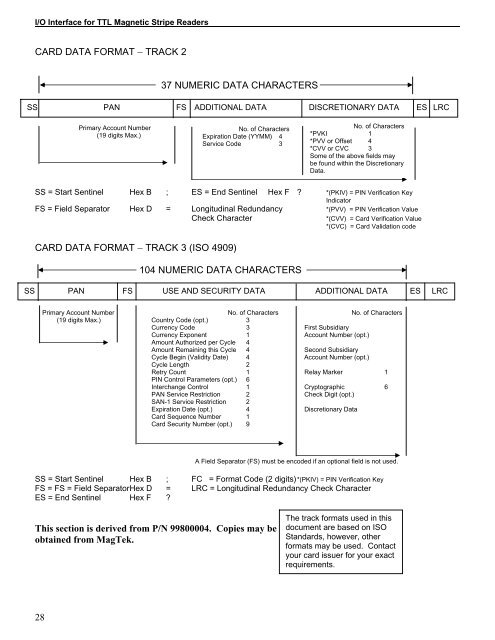
I/O <strong>Interface</strong> <strong>for</strong> <strong>TTL</strong> <strong>Magnetic</strong> <strong>Stripe</strong> <strong>Readers</strong>CARD DATA FORMAT − TRACK 237 NUMERIC DATA CHARACTERSSS PAN FS ADDITIONAL DATA DISCRETIONARY DATA ES LRCPrimary Account Number(19 digits Max.)No. of CharactersExpiration Date (YYMM) 4Service Code 3No. of Characters*PVKI 1*PVV or Offset 4*CVV or CVC 3Some of the above fields maybe found within the DiscretionaryData.SS = Start Sentinel Hex B ; ES = End Sentinel Hex F ? *(PKIV) = PIN Verification KeyIndicatorFS = Field Separator Hex D = Longitudinal Redundancy *(PVV) = PIN Verification ValueCheck CharacterCARD DATA FORMAT − TRACK 3 (ISO 4909)104 NUMERIC DATA CHARACTERS*(CVV) = Card Verification Value*(CVC) = Card Validation codeSS PAN FS USE AND SECURITY DATA ADDITIONAL DATA ES LRCPrimary Account Number No. of Characters No. of Characters(19 digits Max.) Country Code (opt.) 3Currency Code 3 First SubsidiaryCurrency Exponent 1 Account Number (opt.)Amount Authorized per Cycle 4Amount Remaining this Cycle 4 Second SubsidiaryCycle Begin (Validity Date) 4 Account Number (opt.)Cycle Length 2Retry Count 1 Relay Marker 1PIN Control Parameters (opt.) 6Interchange Control 1 Cryptographic 6PAN Service Restriction 2 Check Digit (opt.)SAN-1 Service Restriction 2Expiration Date (opt.) 4 Discretionary DataCard Sequence Number 1Card Security Number (opt.) 9A Field Separator (FS) must be encoded if an optional field is not used.SS = Start Sentinel Hex B ; FC = Format Code (2 digits) *(PKIV) = PIN Verification KeyFS = FS = Field Separator Hex D = LRC = Longitudinal Redundancy Check CharacterES = End Sentinel Hex F ?This section is derived from P/N 99800004. Copies may beobtained from <strong>MagTek</strong>.The track <strong>for</strong>mats used in thisdocument are based on ISOStandards, however, other<strong>for</strong>mats may be used. Contactyour card issuer <strong>for</strong> your exactrequirements.28
APPENDIX D. CARD READER INTERFACEINTERFACING THE CARD READER TO AMICROPROCESSORThe Mag-Tek Card Reader may be interfaced to amicroprocessor unit (MPU) in a number of ways.Selection of the most suitable method will depend on thesystem requirements and the MPU capabilities. The twomost common methods are:1. Single-bit input programming.2. USART (Universal Synchronous/AsynchronousReceiver - Transmitter such as NEC 82C51).SINGLE - BIT INPUT PROGRAMMINGThis method of interface does not require any externalchip to implement serial data communication betweenthe Card Reader and an MPU. This function is donethrough a software program that allows the MPU totransmit and receive data. This process requires somevery time-critical programming. A disadvantage of thisapproach is that, while the processor is receiving dataserially, it must totally dedicate itself to the task.Accurate timing can only be maintained if the programremains in a tight wait loop without being diverted toother functions. When programming the MPU, the timingloops required <strong>for</strong> receiving data cannot exceed the timeperiod of the incoming data bits. Table 1 shows the datarates at card speed of 50 inches per second (ips).TK1 TK2 TK3Bit Rate (bits/sec.) 10,500 3,750 10,500Character Rate (char/sec.) 1,500 750 2,100Table 1 data rates @ 50ipsUSARTThe primary advantage of the USART method is that theMPU is relieved of the critical time-dependentprogramming.The CARD PRESENT signal can be connected to aninput pin on the USART. The DSR input of the USART issuggested as an input of the CARD PRESENT signal tothe MPU. The serial data input (RXD) of the USARTreceives data from the Card Reader. The clock input(RXC) of the USART is connected to the read STROBEoutput of the Card Reader. The USART must be set upto operate in the synchronous mode with a single synccharacter. This sync character must be equivalent to theStart Sentinel character of the track that is being read.When reading Track 1, the user may set the parity onthe USART to ON or OFF. If parity is set to Enabled,then the word size must be set to 6 bits. In this case theUSART checks the character <strong>for</strong> parity error. If the userprefers the parity to be checked by the MPU and not theUSART then parity must be set to Disabled and wordsize must be set to 7 bits. When reading Track 2 orTrack 3, parity must be set to OFF. This is because datacharacters encoded on these two tracks are in 5 bitwords, including parity. The USART is limited to aminimum word size of 5 bits only when parity is OFF. Inthis case, the USART treats the parity bit just like anyother data bit, and the MPU should check <strong>for</strong> correctparity on each character.In operation, the USART remains inactive until itrecognizes the Start Sentinel character. Then it becomesactive and collects the data characters, frames the data,and presents it to the MPU. (In some applications, thismay not be suitable <strong>for</strong> reliable Start Sentinel detection;see the Detecting Start Sentinel discussion below.)When using either method, after the CARD PRESENTsignal indicates that the card is gone, the MPU shouldper<strong>for</strong>m error detection by checking both the parity ofeach character and of the Longitudinal RedundancyCheck (LRC) character. To per<strong>for</strong>m the LRC calculation,each bit of each character excluding the parity bit shouldbe exclusive ORed with the respective bit of allcharacters, including Start Sentinel and End Sentinel.Exclusive ORing the parity bit of all characters does notgenerate the parity bit <strong>for</strong> the LRC character; it is theparity bit <strong>for</strong> the LRC character.The Start Sentinel and the End Sentinel charactersframe data. The first bits encountered by the CardReader are the leading zeros. They indicate to theReader the presence of an encoded magnetic stripecard, and allow the Reader to synchronize itself with theincoming data bits. The leading zeros are followed bythe Start Sentinel character, which indicates thebeginning of data on a track. The characters followingthe Start Sentinel represent the data. The End SentinelCharacter indicates the end of data. After the EndSentinel is the Longitudinal Redundancy Check (LRC)character. Trailing zeros follow the LRC and fill theremainder of the track.NOTE: Characters are encoded on the magnetic stripewith the least significant bit recorded first. The StartSentinel character on Track 2 is recorded as 11010. Thebit pattern is B 0 B 1 B 2 B 3 P. The least significant bit is B 0 .B 3 is the most significant bit. P is the parity bit. Asdefined in the ANSI x4.16 1983, ODD parity is required.The conventional representation of the Start Sentinelwould be 01011 (P B 3 B 2 B 1 B 0 ) or 0Bh (hex).29