USB KB IntelliHead, Technical Reference Manual - MagTek
USB KB IntelliHead, Technical Reference Manual - MagTek
USB KB IntelliHead, Technical Reference Manual - MagTek

You also want an ePaper? Increase the reach of your titles
YUMPU automatically turns print PDFs into web optimized ePapers that Google loves.
<strong>USB</strong> <strong>KB</strong> INTELLIHEADFOR SWIPE READERSTECHNICAL REFERENCE MANUAL<strong>Manual</strong> Part Number 99875321-10JANUARY 2012REGISTERED TO ISO 9001:20081710 Apollo CourtSeal Beach, CA 90740Phone: (562) 546-6400FAX: (562) 546-6301<strong>Technical</strong> Support: (651) 415-6800www.magtek.com
Copyright © 2012<strong>MagTek</strong> ® , Inc.Printed in the United States of AmericaInformation in this document is subject to change without notice. No part of this document may bereproduced or transmitted in any form or by any means, electronic or mechanical, for any purpose,without the express written permission of <strong>MagTek</strong>, Inc.<strong>MagTek</strong> is a registered trademark of <strong>MagTek</strong>, Inc.<strong>IntelliHead</strong> is a trademark of <strong>MagTek</strong>, Inc.<strong>USB</strong> (Universal Serial Bus) Specification is Copyright© 1998 by Compaq Computer Corporation, IntelCorporation, Microsoft Corporation, NEC Corporation.Appendix A is taken from Universal Serial Bus HID Usage Tables, Version 1.12, Section 10,Keyboard/Keypad Page (0x07) ©1996-2005 <strong>USB</strong> Implementers’ Forum.Appendix B is taken from Section 8.3 Report Format for Array Items, Device Class Definition forHuman Interface Devices (HID) Version 1.11, ©1996-2001 <strong>USB</strong> Implementers’ Forum,hidcomments@usb.org.REVISIONSRev Number Date Notes1 28 Jan 05 Initial Release2 10 Jun 05 Added examples to some of the commands; editorial throughout3 8 Aug 05 Sec 1 and Appendices B, C, and D: Included additional models:2103008, 21040132, and 21040133. Sec 4, To, ASCII toKeypress Conversion Type Property, added Active KeymapProperty statement. To Get KeyMap Item Command and SetKeyMap Item Command, added the paragraph, “Starting with thefirmware release…”4 12 Sep 05 Added new Warranty Statement and Appendices G and H, <strong>USB</strong>and HID Usage Table and Device Class Definitions Table5 24 Oct 05 Added new models: 21040137 and 21046004; Updated otherdrawing Revs6 14 Sep 07 Corrected default setting for polling interval. Added 21030016.7 8 Oct 07 Added ES TK1, ES TK2 and ES TK3 properties.8 14 Oct 08 Added JIS type 2 decoding option; updated company address.9 15 Jun 09 Updated Limited Warranty and Agency approvals. Added PanName Date Enable and Post Tk Char Enable Property10 4 Jan 12 Added Host Poll Timeout Property (0x52).ii
LIMITED WARRANTY<strong>MagTek</strong> warrants that the products sold pursuant to this Agreement will perform in accordance with <strong>MagTek</strong>’spublished specifications. This warranty shall be provided only for a period of one year from the date of theshipment of the product from <strong>MagTek</strong> (the “Warranty Period”). This warranty shall apply only to the “Buyer”(the original purchaser, unless that entity resells the product as authorized by <strong>MagTek</strong>, in which event thiswarranty shall apply only to the first repurchaser).During the Warranty Period, should this product fail to conform to <strong>MagTek</strong>’s specifications, <strong>MagTek</strong> will, at itsoption, repair or replace this product at no additional charge except as set forth below. Repair parts andreplacement products will be furnished on an exchange basis and will be either reconditioned or new. All replacedparts and products become the property of <strong>MagTek</strong>. This limited warranty does not include service to repairdamage to the product resulting from accident, disaster, unreasonable use, misuse, abuse, negligence, ormodification of the product not authorized by <strong>MagTek</strong>. <strong>MagTek</strong> reserves the right to examine the allegeddefective goods to determine whether the warranty is applicable.Without limiting the generality of the foregoing, <strong>MagTek</strong> specifically disclaims any liability or warranty forgoods resold in other than <strong>MagTek</strong>’s original packages, and for goods modified, altered, or treated withoutauthorization by <strong>MagTek</strong>.Service may be obtained by delivering the product during the warranty period to <strong>MagTek</strong> (1710 Apollo Court,Seal Beach, CA 90740). If this product is delivered by mail or by an equivalent shipping carrier, the customeragrees to insure the product or assume the risk of loss or damage in transit, to prepay shipping charges to thewarranty service location, and to use the original shipping container or equivalent. <strong>MagTek</strong> will return theproduct, prepaid, via a three (3) day shipping service. A Return Material Authorization (“RMA”) number mustaccompany all returns. Buyers may obtain an RMA number by contacting <strong>Technical</strong> Support at (888) 624-8350.EACH BUYER UNDERSTANDS THAT THIS MAGTEK PRODUCT ISOFFERED AS IS. MAGTEK MAKES NO OTHER WARRANTY, EXPRESS ORIMPLIED, AND MAGTEK DISCLAIMS ANY WARRANTY OF ANY OTHERKIND, INCLUDING ANY WARRANTY OF MERCHANTABILITY OR FITNESSFOR A PARTICULAR PURPOSE.IF THIS PRODUCT DOES NOT CONFORM TO MAGTEK’S SPECIFICATIONS, THE SOLE REMEDYSHALL BE REPAIR OR REPLACEMENT AS PROVIDED ABOVE. MAGTEK’S LIABILITY, IF ANY,SHALL IN NO EVENT EXCEED THE TOTAL AMOUNT PAID TO MAGTEK UNDER THISAGREEMENT. IN NO EVENT WILL MAGTEK BE LIABLE TO THE BUYER FOR ANY DAMAGES,INCLUDING ANY LOST PROFITS, LOST SAVINGS, OR OTHER INCIDENTAL OR CONSEQUENTIALDAMAGES ARISING OUT OF THE USE OF, OR INABILITY TO USE, SUCH PRODUCT, EVEN IFMAGTEK HAS BEEN ADVISED OF THE POSSIBILITY OF SUCH DAMAGES, OR FOR ANY CLAIM BYANY OTHER PARTY.LIMITATION ON LIABILITYEXCEPT AS PROVIDED IN THE SECTIONS RELATING TO MAGTEK’S LIMITED WARRANTY,MAGTEK’S LIABILITY UNDER THIS AGREEMENT IS LIMITED TO THE CONTRACT PRICE OF THISPRODUCT.MAGTEK MAKES NO OTHER WARRANTIES WITH RESPECT TO THE PRODUCT, EXPRESSED ORIMPLIED, EXCEPT AS MAY BE STATED IN THIS AGREEMENT, AND MAGTEK DISCLAIMS ANYIMPLIED WARRANTY, INCLUDING WITHOUT LIMITATION ANY IMPLIED WARRANTY OFMERCHANTABILITY OR FITNESS FOR A PARTICULAR PURPOSE.MAGTEK SHALL NOT BE LIABLE FOR CONTINGENT, INCIDENTAL, OR CONSEQUENTIALDAMAGES TO PERSONS OR PROPERTY. MAGTEK FURTHER LIMITS ITS LIABILITY OF ANY KINDWITH RESPECT TO THE PRODUCT, INCLUDING ANY NEGLIGENCE ON ITS PART, TO THECONTRACT PRICE FOR THE GOODS.MAGTEK’S SOLE LIABILITY AND BUYER’S EXCLUSIVE REMEDIES ARE STATED IN THIS SECTIONAND IN THE SECTION RELATING TO MAGTEK’S LIMITED WARRANTY.iii
FCC WARNING STATEMENTThis equipment has been tested and was found to comply with the limits for a Class B digital device pursuant toPart 15 of FCC Rules. These limits are designed to provide reasonable protection against harmful interferencewhen the equipment is operated in a residential environment. This equipment generates, uses, and can radiateradio frequency energy and, if not installed and used in accordance with the instruction manual, may causeharmful interference with radio communications. However, there is no guarantee that interference will not occurin a particular installation.FCC COMPLIANCE STATEMENTThis device complies with Part 15 of the FCC Rules. Operation of this device is subject to the following twoconditions: (1) this device may not cause harmful interference, and (2) this device must accept any interferencereceived, including interference that may cause undesired operation.CANADIAN DOC STATEMENTThis digital apparatus does not exceed the Class B limits for radio noise from digital apparatus set out in theRadio Interference Regulations of the Canadian Department of Communications.Le présent appareil numérique n’émet pas de bruits radioélectriques dépassant les limites applicables auxappareils numériques de la classe B prescrites dans le Réglement sur le brouillage radioélectrique édicté par leministère des Communications du Canada.This Class B digital apparatus complies with Canadian ICES-003.Cet appareil numériqué de la classe B est conformé à la norme NMB-003 du Canada.CE STANDARDSTesting for compliance with CE requirements was performed by an independent laboratory. The unit under testwas found compliant with standards established for Class B devices.UL/CSAThis product is recognized per Underwriter Laboratories and Canadian Underwriter Laboratories 1950.RoHS STATEMENTWhen ordered as RoHS compliant, this product meets the Electrical and Electronic Equipment (EEE) Reductionof Hazardous Substances (RoHS) European Directive 2002/95/EC. The marking is clearly recognizable, either aswritten words like “Pb-free”, “lead-free”, or as another clear symbol ( ).iv
TABLE OF CONTENTSSECTION 1. FEATURES AND SPECIFICATIONS ..................................................................................... 1FEATURES ............................................................................................................................................... 1HARDWARE CONFIGURATIONS ........................................................................................................... 2ACCESSORIES ........................................................................................................................................ 2REFERENCE DOCUMENTS .................................................................................................................... 2SPECIFICATIONS .................................................................................................................................... 3SECTION 2. INSTALLATION ...................................................................................................................... 5<strong>USB</strong> CONNECTION ................................................................................................................................. 5WINDOWS PLUG AND PLAY SETUP ..................................................................................................... 5MOUNTING ............................................................................................................................................... 5SECTION 3. OPERATION ........................................................................................................................... 7CARD READ ............................................................................................................................................. 7SECTION 4. <strong>USB</strong> COMMUNICATIONS ...................................................................................................... 9HOST APPLICATIONS ............................................................................................................................. 9CARD DATA ............................................................................................................................................. 9PROGRAMMABLE CONFIGURATION OPTIONS ................................................................................. 11LOW LEVEL COMMUNICATIONS ......................................................................................................... 11HID USAGES .......................................................................................................................................... 12REPORT DESCRIPTOR ........................................................................................................................ 12COMMANDS ........................................................................................................................................... 13COMMAND NUMBER ............................................................................................................................ 14DATA LENGTH ....................................................................................................................................... 14DATA ....................................................................................................................................................... 14RESULT CODE....................................................................................................................................... 14GET AND SET PROPERTY COMMANDS ............................................................................................. 15SOFTWARE ID PROPERTY .................................................................................................................. 16SERIAL NUM PROPERTY ..................................................................................................................... 17POLLING INTERVAL PROPERTY ......................................................................................................... 18TRACK ID ENABLE PROPERTY ........................................................................................................... 19TRACK DATA SEND FLAGS PROPERTY ............................................................................................ 20TERMINATION CHAR PROPERTY ....................................................................................................... 21SS TK2 7BITS PROPERTY .................................................................................................................... 21SS TK3 ISO ABA PROPERTY ............................................................................................................... 22SS TK3 AAMVA PROPERTY ................................................................................................................. 22SS TK3 7BITS PROPERTY .................................................................................................................... 22PRE CARD CHAR PROPERTY ............................................................................................................. 23POST CARD CHAR PROPERTY ........................................................................................................... 23PRE TK CHAR PROPERTY ................................................................................................................... 23POST TK CHAR PROPERTY ................................................................................................................. 24ASCII TO KEYPRESS CONVERSION TYPE PROPERTY ................................................................... 24INTERFACE TYPE PROPERTY ............................................................................................................ 25ACTIVE KEYMAP PROPERTY .............................................................................................................. 26PRE CARD STRING PROPERTY .......................................................................................................... 27POST CARD STRING PROPERTY........................................................................................................ 28SS TK1 ISO ABA PROPERTY ............................................................................................................... 28SS TK2 ISO ABA PROPERTY ............................................................................................................... 29ES PROPERTY....................................................................................................................................... 29ES TK1 PROPERTY ............................................................................................................................... 29ES TK2 PROPERTY ............................................................................................................................... 30ES TK3 PROPERTY ............................................................................................................................... 30DECODE ENABLE PROPERTY ............................................................................................................. 31SS JIS TYPE 2 PROPERTY ................................................................................................................... 32ES JIS TYPE 2 PROPERTY ................................................................................................................... 32PAN NAME DATE ENABLE PROPERTY .............................................................................................. 32POST TK CHAR ENABLE PROPERTY ................................................................................................. 34HOST POLL TIMEOUT PROPERTY ...................................................................................................... 34RESET DEVICE COMMAND .................................................................................................................. 36GET KEYMAP ITEM COMMAND ........................................................................................................... 36SET KEYMAP ITEM COMMAND ........................................................................................................... 38SAVE CUSTOM KEYMAP COMMAND .................................................................................................. 40v
SECTION 5. DEMO PROGRAM ................................................................................................................ 41INSTALLATION....................................................................................................................................... 41OPERATION ........................................................................................................................................... 41SOURCE CODE ..................................................................................................................................... 42APPENDIX A. USAGE ID DEFINITIONS .................................................................................................. 43APPENDIX B. MODIFIER BYTE DEFINITIONS ....................................................................................... 51APPENDIX C. DRAWINGS ....................................................................................................................... 53LIST OF FIGURES AND TABLESFigure 1-1. 3-Track <strong>USB</strong> Keyboard Emulation <strong>IntelliHead</strong> ......................................................................... viiiTable 1-1. Specifications .............................................................................................................................. 3Table 2-1. 5-Pin Connector .......................................................................................................................... 5Table A-1. Keyboard/Keypad ..................................................................................................................... 43Table B-1. Modifier Byte ............................................................................................................................. 51Figure C-1. <strong>USB</strong> <strong>KB</strong> <strong>IntelliHead</strong>, 3-Track, 125mm Wire, 5-Pin Connector, Butterfly Spring ..................... 54Figure C-2. <strong>USB</strong> <strong>KB</strong> <strong>IntelliHead</strong>, 3-Track, 275mm Wire, <strong>USB</strong>-A Connector ............................................. 55Figure C-3. <strong>USB</strong> <strong>KB</strong> <strong>IntelliHead</strong>, 3-Track, 125mm Wire, 5-Pin Connector, Accordion Spring .................. 56Figure C-4. <strong>USB</strong> <strong>KB</strong> <strong>IntelliHead</strong>, 3-Track, 6” Cable, <strong>USB</strong>-A Connector, 100mm Black Body ................... 57Figure C-5. <strong>USB</strong> <strong>KB</strong> <strong>IntelliHead</strong>, 3-Track, 6’ Cable, <strong>USB</strong>-A Connector, 100mm Black Body ................... 58Figure C-6. <strong>USB</strong> <strong>KB</strong> <strong>IntelliHead</strong>, 3-Track, 5” Right Angle <strong>USB</strong>-A, 100mm Black Body............................. 59Figure C-7. <strong>USB</strong> <strong>KB</strong> <strong>IntelliHead</strong>, 3-Track, 125mm Wire, 5-pin Molex Connector, 90mm body ................. 60Figure C-8. <strong>USB</strong> <strong>KB</strong> <strong>IntelliHead</strong>, 3-Track, 125mm Wire, 5-pin Molex Connector, 60mm Slim Profile ...... 61Figure C-9. <strong>USB</strong> <strong>KB</strong> <strong>IntelliHead</strong>, 3-Track, 125mm Wire, 5-pin Molex Connector, 90mm Slim Profile ...... 62vi
vii
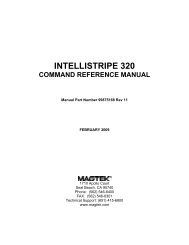
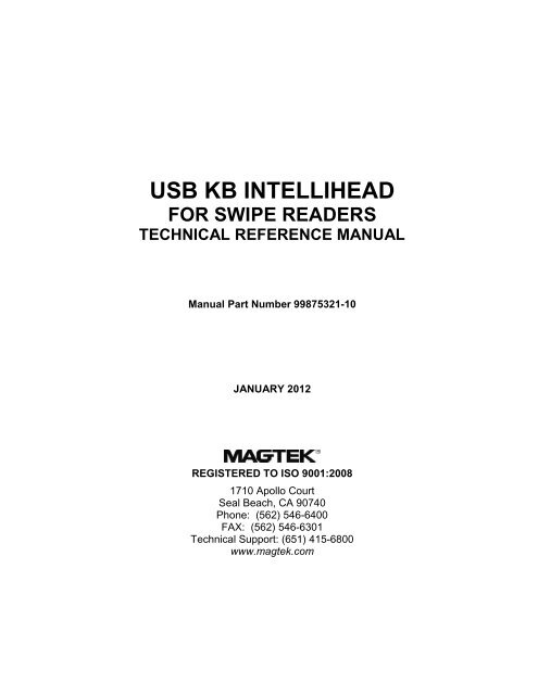
viiiFigure 1-1. 3-Track <strong>USB</strong> Keyboard Emulation <strong>IntelliHead</strong>
SECTION 1. FEATURES AND SPECIFICATIONSThe <strong>USB</strong> (Universal Serial Bus) Keyboard Emulation Swipe Reader is a compact magneticstripe card reader that conforms to ISO standards. The Reader is compatible with any devicewith a <strong>USB</strong> host interface and emulates the operation of a keyboard. A card is read by sliding itpast the head either forward or backward.The Reader emulates a <strong>USB</strong> Human Interface Device (HID) United States keyboard oroptionally all international keyboards using ALT ASCII code keypad key combinations orcustomizable key maps. This allows host applications designed to acquire card data fromkeyboard input to seamlessly acquire the card data from the <strong>USB</strong> swipe reader.CautionIf another keyboard is connected to the same host as this device and akey is pressed on the other keyboard while this device is transmitting,then the data transmitted by this device may get corrupted.Because of potential “data interleave” issues associated with the <strong>USB</strong> Keyboard interface,<strong>MagTek</strong> recommends that the <strong>USB</strong> Keyboard Emulation MSR product should only be used if theapplication requires magnetic stripe data to be provided via the keyboard input. If previousapplications were based upon RS-232 serial interface magnetic stripe readers, or if this is a brandnew development effort, it is recommended that you use <strong>MagTek</strong>’s <strong>USB</strong> HID <strong>IntelliHead</strong>product. (Refer to <strong>Technical</strong> <strong>Manual</strong> 99875320 for further information regarding the <strong>USB</strong> HID<strong>IntelliHead</strong>.)FEATURESMajor features of the <strong>USB</strong> <strong>IntelliHead</strong> are as follows:• Powered through the <strong>USB</strong> – no external power supply required• Hardware Compatible with PC or any computer or terminal with a <strong>USB</strong> interface• Bidirectional card reading• Reads encoded data that meets ANSI/ISO/AAMVA/JIS Type 2 standards and others such asISO track 1 format on track 2 or 3• Reads up to three tracks of card data• Compatible with <strong>USB</strong> specification Revision 1.1• Compatible with HID specification Version 1.1• Can use standard Windows HID drivers for communications. No third part device driver isrequired.• Many programmable configuration options (including the ability to define the Start and EndSentinel characters and to insert a string of characters for the pre- and post-amble characters)• Non-volatile memory for configuration storage• Ability to convert to HID mode of operation1
<strong>USB</strong> Keyboard Emulation Swipe ReaderHARDWARE CONFIGURATIONSThe hardware configurations are as shown in the table below. Drawings of each model areincluded in Appendix C.PartCable Length andDescriptionNumberConnector TypeRail or Housing21030007 <strong>USB</strong> <strong>KB</strong> <strong>IntelliHead</strong> 125mm, 5 pin Molex Butterfly Spring21030008 <strong>USB</strong> <strong>KB</strong> <strong>IntelliHead</strong> 275mm,<strong>USB</strong>-A Butterfly Spring21030016 <strong>USB</strong> <strong>KB</strong> <strong>IntelliHead</strong> 125mm, 5 pin Molex Accordion Spring21040132 <strong>USB</strong> <strong>KB</strong> <strong>IntelliHead</strong> swipe reader 6 in, <strong>USB</strong>-A 100mm Black Body21040133 <strong>USB</strong> <strong>KB</strong> <strong>IntelliHead</strong> swipe reader 6 ft, <strong>USB</strong>-A 100mm Black Body21040137 <strong>USB</strong> <strong>KB</strong> <strong>IntelliHead</strong> swipe reader 6 in, <strong>USB</strong>-A Right Angle 100mm Black Body21045088 <strong>USB</strong> <strong>KB</strong> <strong>IntelliHead</strong> open rail 125mm, 5 pin Molex 90mm Black rail21046004 <strong>USB</strong> <strong>KB</strong> <strong>IntelliHead</strong> 60mm Slim rail 125mm, 5 pin Molex 60mm Black slim rail21047012 <strong>USB</strong> <strong>KB</strong> <strong>IntelliHead</strong> 90mm slim rail 125mm, 5 pin Molex 90mm Black slim railACCESSORIESThe accessories are as follows:Part Number Description21042806 <strong>USB</strong> MSR Demo Program with Source Code (disk)21051534 Test Cable to convert from <strong>IntelliHead</strong> to <strong>USB</strong>-A (6 ft)99510026 <strong>USB</strong> MSR Demo Program with Source Code (WEB)REFERENCE DOCUMENTS<strong>MagTek</strong> Magnetic Card Reader Design Kit <strong>Technical</strong> Specification (99821002)<strong>MagTek</strong> <strong>USB</strong> HID <strong>IntelliHead</strong> for Swipe Readers, <strong>Technical</strong> <strong>Reference</strong> <strong>Manual</strong> (99875320)Axelson, Jan. <strong>USB</strong> Complete, Everything You Need to Develop Custom <strong>USB</strong> Peripherals, 1999.Lakeview Research, 2209 Winnebago St., Madison WI 53704, 396pp., http://www.lvr.com<strong>USB</strong> Human Interface Device (HID) Class Specification Version 1.1Universal Serial Bus (<strong>USB</strong>): HID Usage Tables Version 1.12 (1/21/2005)<strong>USB</strong> (Universal Serial Bus) Specification, Version 1.1, Copyright © 1998 by Compaq ComputerCorporation, Intel Corporation, Microsoft Corporation, NEC Corporation<strong>USB</strong> Implementers Forum, Inc., www.usb.org2
Section 1. Features and SpecificationsSPECIFICATIONSTable 1-1 lists the specifications for the <strong>USB</strong> <strong>IntelliHead</strong>.Table 1-1. Specifications<strong>Reference</strong> Standards ISO 7810, ISO 7811, AAMVA and JIS X 6302*Power Input5V from <strong>USB</strong> busRecording MethodTwo-frequency coherent phase (F2F)Message FormatASCIICard Speed3 to 60 ips (7.62 – 152.4 cm/s)ELECTRICALCurrentNormal ModeSuspend Mode15mA200 µAMECHANICALWeight1.1 oz. (31 gr.)Cable lengthConnectorSee related drawing in Appendix CSee related drawing in Appendix CENVIRONMENTALTemperatureOperating -40 o C to +70 o C (-40 o F to 158 o F)Storage -40 o C to +70 o C (-40 o F to 158 o F)HumidityOperating10% to 90% noncondensingStorage10% to 90% noncondensingAltitudeOperating0-10,000 ft. (0-3048 m.)Storage0-50,000 ft. (0-15240 m.)* ISO (International Standards Organization, AAMVA (American Association of MotorVehicle Administrators) and JIS (Japanese Industrial Standard).3
<strong>USB</strong> Keyboard Emulation Swipe Reader4
SECTION 2. INSTALLATIONThis section describes the cable connection, the Windows Plug and Play Setup, and the physicalmounting of the unit.<strong>USB</strong> CONNECTIONSince the <strong>USB</strong> <strong>IntelliHead</strong> is supplied as an OEM product, the installation and system integrationwill be unique for each application. The reader module must be attached to an appropriateconnector which, in turn, connects to the <strong>USB</strong> port or hub.Pin numbers and signal descriptions for the cable shown in the illustration are listed in Table 2-1.The connector is a Molex 52021-0500; one of the recommended mating connectors is Molex53048-0510.Table 2-1. 5-Pin ConnectorPin Number Signal Cable Color1 VBUS Red2 - Data White3 +Data Green4 Ground Black5 Head Case BrownWINDOWS PLUG AND PLAY SETUPOn hosts with the Windows operating system, the first time the device is plugged into a specific<strong>USB</strong> port, Windows will pop up a dialog box, which will guide you through the process ofinstalling a device driver for the device. After this process is completed once, Windows will nolonger request this process as long as the device is plugged into the same <strong>USB</strong> port. The devicedriver that Windows will install for this device is the driver used for HID keyboard devices and itis part of the Windows operating system. When the dialog box pops up, follow the instructionsgiven in the dialog box. Sometimes, Windows will find all the files it needs. Other timesWindows will need to know the location of the files it needs. If Windows prompts for the filelocations, insert the CD that was used to install Windows on your PC and point Windows to theroot directory of the CD. Windows should find all the files it needs there.MOUNTINGRefer to the appropriate Appendix in this document and/or to the Magnetic Card Reader DesignKit for complete mounting details.5
<strong>USB</strong> Keyboard Emulation Swipe Reader6
SECTION 3. OPERATIONCARD READA card may be swiped past the read head at any time. The magnetic stripe must face toward thehead and may be swiped in either direction. If there is data encoded on the card, the device willattempt to decode the data and then send the results to the host via a <strong>USB</strong> HID input report.After the results are sent to the host, all card data will be purged from the device, then the devicewill be ready to read the next card.7
<strong>USB</strong> Keyboard Emulation Swipe Reader8
SECTION 4. <strong>USB</strong> COMMUNICATIONSThis device conforms to the <strong>USB</strong> specification revision 1.1. This device also conforms with theHuman Interface Device (HID) class specification version 1.1. The device communicates to thehost as a HID keyboard device. The latest versions of the Windows operating systems comewith a standard Windows <strong>USB</strong> HID keyboard driver.This is a full speed <strong>USB</strong> device. This device has a number of programmable configurationproperties. These properties are stored in non-volatile memory. These properties can beconfigured at the factory or by the end user. The device has an adjustable endpoint descriptorpolling interval value that can be set to any value in the range of 1ms to 255ms. This propertycan be used to speed up or slow down the card data transfer rate. The device also has anadjustable serial number descriptor. More details about these properties can be found later in thisdocument in the command section.The device will go into suspend mode when directed to do so by the host. The device will wakeup from suspend mode when directed to do so by the host. The device does not support remotewakeup.This device is powered from the <strong>USB</strong> bus. The vendor ID is 0x0801 and the product ID is0x0001.HOST APPLICATIONSThis device can be used with existing applications that acquire card data via keyboard input.Also, applications that communicate to this device can be easily developed. These applicationscan be developed using compilers such as Microsoft’s Visual Basic or Visual C++. Todemonstrate this device’s card reading capabilities any application that accepts keyboard inputsuch as Window’s Notepad can be used.CARD DATAThe card data is converted to ASCII and transmitted to the host as if it had been typed on akeyboard. Any data with ASCII values 0 – 31 or 127 will be transmitted as their equivalentcontrol code combination. For example a carriage return value 13 (0x0D) will be sent as (^M)where ^ represents the Ctrl key on the keyboard.CautionIf another keyboard is connected to the same host as this device and akey is pressed on the other keyboard while this device is transmitting,then the data transmitted by this device may get corrupted.9
<strong>USB</strong> Keyboard Emulation Swipe ReaderBecause of potential “data interleave” issues associated with the <strong>USB</strong> Keyboard interface,<strong>MagTek</strong> recommends that the <strong>USB</strong> Keyboard Emulation MSR product should only be used bycustomers who have previously used <strong>MagTek</strong>’s Keyboard Wedge MSR, or who are interfacingwith an existing PC software application which gathers card data from the keyboard port. Ifprevious applications were based upon RS-232 serial interface MSRs, or if this is a brand newdevelopment effort, it is recommended that you use the <strong>MagTek</strong>’s <strong>USB</strong> HID <strong>IntelliHead</strong> MSR(Non-Keyboard Emulation Version). Refer to <strong>Technical</strong> <strong>Manual</strong> 99875320 for furtherinformation regarding the <strong>USB</strong> <strong>IntelliHead</strong> HID reader.The device’s programmable configuration options affect the format of the card data.The card data format for the default configuration is as follows:[Tk1 SS] [Tk1 Data] [ES] [Tk2 SS] [Tk2 Data] [ES] [Tk3 SS] [Tk3 Data] [ES] [CR]where:Tk1 SS = % (7-bit start sentinel)Tk2 SS = ; (ISO/ABA 5-bit start sentinel)@ (7-bit start sentinel)DEL (0x7F) (JIS type 2 start sentinel)*Tk3 SS = + (ISO/ABA start sentinel)# (AAMVA start sentinel)& (7-bit start sentinel)ES = ? (end sentinel for all formats except JIS type 2)DEL (7F hex) (JIS type 2 end sentinel)*CR = (carriage return) (0x0D)* Before the JIS type 2 encode type can be decoded, decoding must be enabled with the decodeenable property. The JIS type 2 decoding option was not added until firmware with software ID21042812K01 was release in October 2008. Some applications may not work well with the JIStype 2 format because this format allows ASCII characters in the non-printable range (0x00 – 0x1Fand 0x7F).All data will be sent in upper case regardless of the state of the caps lock key on the keyboard. Ifno data is detected on a track then nothing will be transmitted for that track. If an error isdetected on a track the ASCII character E will be sent in place of the track data to indicate anerror.The card data format for all programmable configuration options is as follows:[P18][P11] [P13] [Tk1 SS] [Tk1 Data] [ES] [LRC] [P14] [P5] [P13] [Tk2 SS] [Tk2 Data] [ES][LRC] [P14] [P5] [P13] [Tk3 SS] [Tk3 Data] [ES] [LRC] [P14] [P5] [P12][P19]10
Section 4. <strong>USB</strong> Communicationswhere:ES = P22 (end sentinel)LRC = Longitudinal redundancy check characterP5 = Terminating characterP11 = Pre card characterP12 = Post card characterP13 = Pre track characterP14 = Post track characterP18 = Pre card stringP19 = Post card stringTk1 SS = P20 (ISO/ABA start sentinel)Tk2 SS = P21 (ISO/ABA 5-bit start sentinel)P6 (7-bit start sentinel)Tk3 SS = P8 (ISO/ABA start sentinel)P9 (AAMVA start sentinel)P10 (7-bit start sentinel)All fields with the format P# are programmable configuration property numbers. They aredescribed in detail later in this document.PROGRAMMABLE CONFIGURATION OPTIONSThis device has a number of programmable configuration properties. These properties are storedin non-volatile memory. These properties can be configured at the factory or by the end userusing a program supplied by <strong>MagTek</strong>. Programming these parameters requires low levelcommunications with the device. During normal device operation, the device acts like a <strong>USB</strong>HID keyboard so the host operating system takes care of all low level communications with thedevice so that the application developer is not burdened with these low level details. Details onhow to communicate with the device to change programmable configuration properties followsin the next few sections. These details are included as a reference only. Most users will not needto know these details because the device will be configured at the factory or by a programsupplied by <strong>MagTek</strong>. Most users may want to skip over the next few sections on low levelcommunications and continue with the details of the configuration properties.LOW LEVEL COMMUNICATIONSIt is strongly recommended that application software developers become familiar with the HIDspecification the <strong>USB</strong> specification before attempting to communicate directly with this device.This document assumes that the reader is familiar with these specifications. These specificationscan be downloaded free from www.usb.org.11
<strong>USB</strong> Keyboard Emulation Swipe ReaderHID USAGESHID devices send data in reports. Elements of data in a report are identified by unique identifierscalled usages. The structure of the device’s reports and the device’s capabilities are reported tothe host in a report descriptor. The host usually gets the report descriptor only once, right afterthe device is plugged in. The report descriptor usages identify the devices capabilities and reportstructures. For example, a device could be identified as a keyboard by analyzing the device’sreport descriptor. Usages are four byte integers. The most significant two bytes are called theusage page and the least significant two bytes are called usage IDs. Usages that are related canshare a common usage page. Usages can be standardized or they can be vendor defined.Standardized usages such as usages for mice and keyboards can be found in the HID UsageTables document and can be downloaded free at www.usb.org. Vendor defined usages musthave a usage page in the range 0xff00 – 0xffff. All usages for this device use the standard HIDkeyboard usages or vendor defined magnetic stripe reader usage page 0xff00. The vendordefined usage IDs for this device are defined in the following table. The usage types are alsolisted. These usage types are defined in the HID Usage Tables document.Magnetic Stripe Reader usage page 0xff00:Usage ID Usage NameUsage Report(Hex)Type Type20 Command message Data FeatureREPORT DESCRIPTORThe HID report descriptor is structured as follows:ItemValue(Hex)Usage Page (Generic Desktop) 05 01Usage (Keyboard) 09 06Collection (Application) A1 01Usage Page (Key Codes) 05 07Usage Minimum (224)19 E0Usage Maximum (231)29 E7Logical Minimum (0) 15 00Logical Maximum (1) 25 01Report Size (1) 75 01Report Count (8) 95 08Input (Data, Variable, Absolute) 81 02Report Count (1) 95 01Report Size (8) 75 08Input (Constant) 81 03Report Count (5) 95 05Report Size (1) 75 01Usage Page (LEDs) 05 08Usage Minimum (1) 19 01Usage Maximum (5) 29 05Output (Data, Variable, Absolute) 91 0212
Section 4. <strong>USB</strong> CommunicationsItemValue(Hex)Report Count (1) 95 01Report Size (3) 75 03Output (Constant) 91 03Report Count (6) 95 06Report Size (8) 75 08Logical Minimum (0) 15 00Logical Maximum (101) 25 66Usage Page (Key Codes) 05 07Usage Minimum (0) 19 00Usage Maximum (101) 29 66Input (Data, Array) 81 00Logical Maximum (255) 26 FF 00Usage Page (vendor defined (MSR))06 00 FFUsage (command data) 09 20Report Count 95 18Feature (Data, Variable, Absolute, Buffered Bytes) B2 02 01End CollectionC0COMMANDSCommand requests and responses are sent to and received from the device using feature reports.Command requests are sent to the device using the HID class specific request Set Report. Theresponse to a command is retrieved from the device using the HID class specific request GetReport. These requests are sent over the default control pipe. When a command request is sent,the device will Nak the Status stage of the Set Report request until the command is completed.This insures that as soon as the Set Report request is completed, the Get Report request can besent to get the command response. The usage ID for the command message was shownpreviously in the Usage Table.The following table shows how the feature report is structured for command requests:OffsetField Name0 Command Number1 Data Length2 – 23 DataThe following table shows how the feature report is structured for command responses.OffsetField Name0 Result Code1 Data Length2 – 23 Data13
<strong>USB</strong> Keyboard Emulation Swipe ReaderCOMMAND NUMBERThis one-byte field contains the value of the requested command number. The following tablelists all the existing commands.Value Command Number Description(Hex)00 GET PROPERTY Gets a property from the device01 SET PROPERTY Sets a property in the device02 RESET DEVICE Resets the device03 GET KEYMAP ITEM Gets a key map item04 SET KEYMAP ITEM Sets a key map item05 SAVE CUSTOM KEYMAP Saves the custom key mapDATA LENGTHThis one-byte field contains the length of the valid data contained in the Data field.DATAThis multi-byte field contains command data if any. Note that the length of this field is fixed at22 bytes. Valid data should be placed in the field starting at offset 2. Any remaining data afterthe valid data should be set to zero. This entire field must always be set even if there is no validdata. The HID specification requires that Reports be fixed in length. Command data may varyin length. Therefore, the Report should be filled with zeros after the valid data.RESULT CODEThis one-byte field contains the value of the result code. There are two types of result codes:generic result codes and command-specific result codes. Generic result codes always have themost significant bit set to zero. Generic result codes have the same meaning for all commandsand can be used by any command. Command-specific result codes always have the mostsignificant bit set to one. Command-specific result codes are defined by the command that usesthem. The same code can have different meanings for different commands. Command-specificresult codes are defined in the documentation for the command that uses them. Generic resultcodes are defined in the following table.Value Result CodeDescription(Hex)00 SUCCESS The command completed successfully.01 FAILURE The command failed.02 BAD PARAMETER The command failed due to a badparameter or command syntax error.14
Section 4. <strong>USB</strong> CommunicationsGET AND SET PROPERTY COMMANDSThe Get Property command gets a property from the device. The Get Property commandnumber is 0x00.The Set Property command sets a property in the device. The Set Property command numberis 0x01.The Get and Set Property command data fields for the requests and responses are structured asfollows:Get Property Request Data:Data Offset Value0 Property IDGet Property Response Data:Data Offset Value0 – n Property ValueSet Property Request Data:Data OffsetValue0 Property ID1 – n Property ValueSet Property Response Data:NoneThe result codes for the Get and Set Property commands can be any of the codes list in thegeneric result code table.Property ID is a one-byte field that contains a value that identifies the property. The followingtable lists all the current property ID values:Value Property IDDescription(Hex)00 SOFTWARE ID The device’s software identifier01 SERIAL NUM The device’s serial number02 POLLING INTERVAL The interrupt pipe’s polling interval03 TRACK ID ENABLE Track enable / ID enable04 TRACK DATA SEND FLAGS Track data send flags05 TERMINATION CHAR Terminating char / per track or card flag06 SS TK2 7BITS Start sentinel char for track 2 – 7 bit data08 SS TK3 ISO ABA Start sentinel char for track 3 – ISO/ABA09 SS TK3 AAMVA Start sentinel char for track 3 - AAMVA0A SS TK3 7BITS Start sentinel char for track 3 – 7 bit data0B PRE CARD CHAR Pre card char0C POST CARD CHAR Post card char0D PRE TK CHAR Pre track char0E POST TK CHAR Post track char0F ASCII TO KEYPRESS CONVERSION TYPE Type of conversion performed whenconverting ASCII data to key strokes15
<strong>USB</strong> Keyboard Emulation Swipe ReaderValue Property IDDescription(Hex)10 INTERFACE TYPE Type of <strong>USB</strong> interface11 ACTIVE KEYMAP Selects which key map to uses12 PRE CARD STRING Pre card string13 POST CARD STRING Post card string14 SS TK1 ISO ABA Start sentinel char for track 1 – ISO/ABA16 SS TK2 ISO ABA Start sentinel char for track 2 – ISO/ABA16 ES End sentinel char for all tracks/formatsexcept JIS type 217 ES TK1 End sentinel char for track 118 ES TK2 End sentinel char for track 2 except JIS type219 ES TK3 End sentinel char for track 31A DECODE ENABLE Enables decoding for certain formats1B SS JIS TYPE 2 Start sentinel char for JIS type 21C ES JIS TYPE 2 End sentinel char for JIS type 21D PAN NAME DATE ENABLE Enables PAN name data format1E POST TK CHAR ENABLE Enables the post track character per track52 HOST POLL TIMEOUT Allows <strong>USB</strong> poll timeout to be adjustedThe Property Value is a multiple-byte field that contains the value of the property. The numberof bytes in this field depends on the type of property and the length of the property. Thefollowing table lists all of the property types and describes them.Property TypeByteStringDescriptionThis is a one-byte value. The valid values depend on the property.This is a multiple byte ASCII string. Its length can be zero to amaximum length that depends on the property. The value andlength of the string does not include a terminating NUL character.SOFTWARE ID PROPERTYProperty ID: 0x00Property Type: StringLength: Fixed at 11 bytesGet Property: YesSet Property: NoDescription: This is an 11 byte read only property that identifies the software part numberand version for the device. The first 8 bytes represent the part number and thelast 3 bytes represent the version. For example this string might be“21042812D01”. Examples follow:Example Get Software ID property Request (Hex):Cmd Num Data Len Prp ID00 01 00Example Get Software ID property Response (Hex):Result Code Data Len Prp Value00 01 32 31 30 34 32 38 31 32 44 30 3116
Section 4. <strong>USB</strong> CommunicationsSERIAL NUM PROPERTYProperty ID: 0x01Property Type: StringLength: 0 – 15 bytesGet Property: YesSet Property: YesDefault Value: The default value is no string with a length of zero.Description: The value is an ASCII string that represents the device’s serial number. Thisstring can be 0 – 15 bytes long. The value of this property, if any, will be sentto the host when the host requests the <strong>USB</strong> string descriptor.This property is stored in non-volatile memory, so it will persist when the unitis power cycled. When this property is changed, the unit must be reset (seeCommand Number 2) or power cycled to have these changes take effect.Example Set Serial Num property Request (Hex):Cmd Num Data Len Prp ID Prp Value01 04 01 31 32 33Example Set Serial Num property Response (Hex):Result Code Data Len Data00 00Example Get Serial Num property Request (Hex):Cmd Num Data Len Prp ID00 01 01Example Get Serial Num property Response (Hex):Result Code Data Len Prp Value00 03 31 32 3317
<strong>USB</strong> Keyboard Emulation Swipe ReaderPOLLING INTERVAL PROPERTYProperty ID: 0x02Property Type: ByteLength: 1 byteGet Property: YesSet Property: YesDefault Value: 1Description: The value is a byte that represents the devices polling interval for the InterruptIn Endpoint. The value can be set in the range of 1 – 255 and has units ofmilliseconds. The polling interval tells the host how often to poll the devicefor card data packets. For example, if the polling interval is set to 10, the hostwill poll the device for card data packets every 10ms. This property can beused to speed up or slow down the time it takes to send card data to the host.The trade-off is that speeding up the card data transfer rate increases the <strong>USB</strong>bus bandwidth used by the device, and slowing down the card data transferrate decreases the <strong>USB</strong> bus bandwidth used by the device. The value of thisproperty will be sent to the host when the host requests the device’s <strong>USB</strong>endpoint descriptor.This property is stored in non-volatile memory, so it will persist when the unitis power cycled. When this property is changed, the unit must be reset (seeCommand Number 2) or power cycled to have these changes take effect.Example Set Polling Interval property Request (Hex):Cmd Num Data Len Prp ID Prp Value01 02 02 0AExample Set Polling Interval property Response (Hex):Result Code Data Len Data00 00Example Get Polling Interval property Request (Hex):Cmd Num Data Len Prp ID00 01 02Example Get Polling Interval property Response (Hex):Result Code Data Len Prp Value00 01 0A18
Section 4. <strong>USB</strong> CommunicationsTRACK ID ENABLE PROPERTYProperty ID: 0x03Property Type: ByteLength: 1 byteGet Property: YesSet Property: YesDefault Value: 0x95Description: This property is defined as follows:id 0 T 3 T 3 T 2 T 2 T 1 T 1IdT #0 – Decodes standard ISO/ABA cards only1 – Decodes AAMVA, CA DL/ID and 7-bit cards also00 – Track Disabled01 – Track Enabled10 – Track Enabled/Required (Error if blank)This property is stored in non-volatile memory, so it will persist when the unit ispower cycled. When this property is changed, the unit must be reset (seeCommand Number 2) or power cycled to have these changes take effect.Example Set Track ID Enable property Request (Hex):Cmd Num Data Len Prp ID Prp Value01 02 03 95Example Set Track ID Enable property Response (Hex):Result Code Data Len Data00 00Example Get Track ID Enable property Request (Hex):Cmd Num Data Len Prp ID00 01 03Example Get Track ID Enable property Response (Hex):Result Code Data Len Prp Value00 01 9519
<strong>USB</strong> Keyboard Emulation Swipe ReaderTRACK DATA SEND FLAGS PROPERTYProperty ID: 0x04Property Type: ByteLength: 1 byteGet Property: YesSet Property: YesDefault Value: 0x63Description: This property is defined as follows:ICL SS ES LRC 0 LC Er ErICLSSESLRC0 – Changing the state of the caps lock key will not affect the case of the data1 – Changing the state of the caps lock key will affect the case of the data0 – Don’t send Start Sentinel for each track1 – Send Start Sentinel for each track0 – Don’t send End Sentinel for each track1 – Send End Sentinel for each track0 – Don’t send LRC for each track1 – Send LRC for each trackNote that the LRC is the unmodified LRC from the track data. To verify the LRCthe track data needs to be converted back from ASCII to card data format and thestart sentinels that were modified to indicate the card encode type need to beconverted back to their original values.LC0 – Send card data as upper case1 – Send card data as lower caseNote that the state of the Caps Lock key on the host keyboard has no affect onwhat case the card data is transmitted in unless the ICL bit in this property is setto 1.Er00 – Don’t send any card data if error01 – Don’t send track data if error11 – Send ‘E’ for each track errorThis property is stored in non-volatile memory, so it will persist when the unit ispower cycled. When this property is changed, the unit must be reset (seeCommand Number 2) or power cycled to have these changes take effect.20
Section 4. <strong>USB</strong> CommunicationsTERMINATION CHAR PROPERTYProperty ID: 0x05Property Type: ByteLength: 1 byteGet Property: YesSet Property: YesDefault Value: 0x0D (carriage return)Description: This property is defined as follows:mod c c c c c c cmodc0 – Send c after card data1 – Send c after each track1-127 – 7 bit ASCII char code0 – send nothingThis property is stored in non-volatile memory, so it will persist when the unit ispower cycled. When this property is changed, the unit must be reset (seeCommand Number 2) or power cycled to have these changes take effect.SS TK2 7BITS PROPERTYProperty ID: 0x06Property Type: ByteLength: 1 byteGet Property: YesSet Property: YesDefault Value: 0x40 ‘@’Description: This character is sent as the track 2 start sentinel for cards that have track 2encoded in 7 bits per character format. If the value is 0 no character is sent. Ifthe value is in the range 1 – 127 then the equivalent ASCII character will besent.This property is stored in non-volatile memory, so it will persist when the unitis power cycled. When this property is changed, the unit must be reset (seeCommand Number 2) or power cycled to have these changes take effect.21
<strong>USB</strong> Keyboard Emulation Swipe ReaderSS TK3 ISO ABA PROPERTYProperty ID: 0x08Property Type: ByteLength: 1 byteGet Property: YesSet Property: YesDefault Value: 0x2B ‘+’Description: This character is sent as the track 3 start sentinel for cards that have track 3encoded in ISO/ABA format. If the value is 0 no character is sent. If thevalue is in the range 1 – 127 then the equivalent ASCII character will be sent.This property is stored in non-volatile memory, so it will persist when the unitis power cycled. When this property is changed, the unit must be reset (seeCommand Number 2) or power cycled to have these changes take effect.SS TK3 AAMVA PROPERTYProperty ID: 0x09Property Type: ByteLength: 1 byteGet Property: YesSet Property: YesDefault Value: 0x23 ‘#’Description: This character is sent as the track 3 start sentinel for cards that have track 3encoded in AAMVA format. If the value is 0 no character is sent. If thevalue is in the range 1 – 127 then the equivalent ASCII character will be sent.This property is stored in non-volatile memory, so it will persist when the unitis power cycled. When this property is changed, the unit must be reset (seeCommand Number 2) or power cycled to have these changes take effect.SS TK3 7BITS PROPERTYProperty ID: 0x0AProperty Type: ByteLength: 1 byteGet Property: YesSet Property: YesDefault Value: 0x26 ‘&’Description: This character is sent as the track 3 start sentinel for cards that have track 3encoded in 7 bits per character format. If the value is 0 no character is sent. Ifthe value is in the range 1 – 127 then the equivalent ASCII character will besent.This property is stored in non-volatile memory, so it will persist when the unitis power cycled. When this property is changed, the unit must be reset (seeCommand Number 2) or power cycled to have these changes take effect.22
Section 4. <strong>USB</strong> CommunicationsPRE CARD CHAR PROPERTYProperty ID: 0x0BProperty Type: ByteLength: 1 byteGet Property: YesSet Property: YesDefault Value: 0Description: This character is sent prior to all other card data. If the value is 0 no characteris sent. If the value is in the range 1 – 127 then the equivalent ASCIIcharacter will be sent.This property is stored in non-volatile memory, so it will persist when the unitis power cycled. When this property is changed, the unit must be reset (seeCommand Number 2) or power cycled to have these changes take effect.POST CARD CHAR PROPERTYProperty ID: 0x0CProperty Type: ByteLength: 1 byteGet Property: YesSet Property: YesDefault Value: 0Description: This character is sent after all other card data. If the value is 0 no character issent. If the value is in the range 1 – 127 then the equivalent ASCII characterwill be sent.This property is stored in non-volatile memory, so it will persist when the unitis power cycled. When this property is changed, the unit must be reset (seeCommand Number 2) or power cycled to have these changes take effect.PRE TK CHAR PROPERTYProperty ID: 0x0DProperty Type: ByteLength: 1 byteGet Property: YesSet Property: YesDefault Value: 0Description: This character is sent prior to the data for each track. If the value is 0 nocharacter is sent. If the value is in the range 1 – 127 then the equivalentASCII character will be sent.This property is stored in non-volatile memory, so it will persist when the unitis power cycled. When this property is changed, the unit must be reset (seeCommand Number 2) or power cycled to have these changes take effect.23
<strong>USB</strong> Keyboard Emulation Swipe ReaderPOST TK CHAR PROPERTYProperty ID: 0x0EProperty Type: ByteLength: 1 byteGet Property: YesSet Property: YesDefault Value: 0Description: This character is sent after the data for each track. If the value is 0 nocharacter is sent. If the value is in the range 1 – 127 then the equivalentASCII character be sent.This property is stored in non-volatile memory, so it will persist when the unitis power cycled. When this property is changed, the unit must be reset (seeCommand Number 2) or power cycled to have these changes take effect.ASCII TO KEYPRESS CONVERSION TYPE PROPERTYProperty ID: 0x0FProperty Type: ByteLength: 1 byteGet Property: YesSet Property: YesDefault Value: 0 (keymap)Description: The value is a byte that represents the devices ASCII to keypress conversiontype. The value can be set to 0 for keymap (The active keymap is set with theACTIVE KEYMAP property) or to 1 for ALT ASCII code (internationalkeyboard emulation). When the value is set to 0 (keymap), data will betransmitted to the host according to the active keymap which defaults to theUnited States keyboard keymap. For example, to transmit the ASCIIcharacter ‘?’ (063 decimal), the character is looked up in a keymap. For aUnited States keyboard keymap, the ‘/’ (forward slash) key combined with theleft shift key modifier are stored in the keymap to represent the key presscombination that is used to represent the ASCII character ‘?’ (063 decimal).When the value is set to 1 (ALT ASCII code), instead of using the key map,an international keyboard key press combination consisting of the decimalvalue of the ASCII character combined with the ALT key modifier is used.For example, to transmit the ASCII character ‘?’ (063 decimal), keypad ‘0’ issent combined with left ALT key modifier, next keypad ‘6’ is sent combinedwith the left ALT key modifier, last keypad ‘3’ is sent combined with the leftALT key modifier. In general, if this device only needs to emulate UnitedStates keyboards then this property should be set to 0 (keymap).If this device needs to be able to emulate all country’s keyboards then this property should be setto 1 (ALT ASCII code). The tradeoff is that the ALT ASCII code mode isslightly slower than keymap mode because more key presses need to betransmitted. Some applications are not compatible with ALT ASCII codemode.24
<strong>USB</strong> Keyboard Emulation Swipe ReaderExample Set Interface Type property to HID Request (Hex):Cmd Num Data Len Prp ID Prp Value01 02 10 00Example Set Interface Type property Response (Hex):Result Code Data Len Data00 00Example Get Interface Type property Request (Hex):Cmd Num Data Len Prp ID00 01 10Example Get Interface Type property Response (Hex):Result Code Data Len Prp Value00 01 00ACTIVE KEYMAP PROPERTYProperty ID: 0x11Property Type: ByteLength: 1 byteGet Property: YesSet Property: YesDefault Value: 0 (United States)Description: The value is a byte that represents the device’s active key map. The value canbe set to 0 for the United States key map or to 1 for the custom key map. Theactive key map will be used by the device to convert ASCII data into keystrokes. The United States key map should be used will all hosts that areconfigured to use United States keyboards. The custom key map can be usedto set up the device to work with hosts that are configured to use othercountries keyboards. The default custom key map is the same as the UnitedStates key map. The key map can be modified to another countries key mapby using commands “Get Key Map”, “Set Key Map” and “Save Custom KeyMap”. See the command section of this manual for a complete description ofthese commands. To set up a device to use a custom key map, select theappropriate key map to be modified using the active key map property, resetthe device to make this change take affect, use the “Get Key Map” and “SetKey Map” commands to modify the active key map, use the “Save CustomKey Map” command to save the active key map as the custom key map, setthe active key map property to custom to use the custom key map, reset thedevice to make these changes take affect.This property is stored in non-volatile memory, so it will persist when the unitis power cycled. When this property is changed, the unit must be reset (seeCommand Number 2) or power cycled to have these changes take effect.26
Section 4. <strong>USB</strong> CommunicationsExample Set Active Keymap property Request (Hex):Cmd Num Data Len Prp ID Prp Value01 02 11 00Example Set Active Keymap property Response (Hex):Result Code Data Len Data00 00Example Get Active Keymap property Request (Hex):Cmd Num Data Len Prp ID00 01 11Example Get Active Keymap property Response (Hex):Result Code Data Len Prp Value00 01 00PRE CARD STRING PROPERTYProperty ID: 0x12Property Type: StringLength: 0 – 7 bytesGet Property: YesSet Property: YesDefault Value: The default value is no string with a length of zero.Description: The value is an ASCII string that represents the device’s pre card string. Thisstring can be 0 – 7 bytes long. This string is sent prior to all other card data.This property is stored in non-volatile memory, so it will persist when the unitis power cycled. When this property is changed, the unit must be reset (seeCommand Number 2) or power cycled to have these changes take effect.Example Set Pre Card String property Request (Hex):Cmd Num Data Len Prp ID Prp Value01 04 12 31 32 33Example Set Pre Card String property Response (Hex):Result Code Data Len Data00 00Example Get Pre Card String property Request (Hex):Cmd Num Data Len Prp ID00 01 12Example Get Pre Card String property Response (Hex):Result Code Data Len Prp Value00 03 31 32 3327
<strong>USB</strong> Keyboard Emulation Swipe ReaderPOST CARD STRING PROPERTYProperty ID: 0x13Property Type: StringLength: 0 – 7 bytesGet Property: YesSet Property: YesDefault Value: The default value is no string with a length of zero.Description: The value is an ASCII string that represents the device’s post card string.This string can be 0 – 7 bytes long. This string is sent after all other card data.This property is stored in non-volatile memory, so it will persist when the unitis power cycled. When this property is changed, the unit must be reset (seeCommand Number 2) or power cycled to have these changes take effect.Example Set Post Card String property Request (Hex):Cmd Num Data Len Prp ID Prp Value01 04 12 31 32 33Example Set Post Card String property Response (Hex):Result Code Data Len Data00 00Example Get Post Card String property Request (Hex):Cmd Num Data Len Prp ID00 01 12Example Get Post Card String property Response (Hex):Result Code Data Len Prp Value00 03 31 32 33SS TK1 ISO ABA PROPERTYProperty ID: 0x14Property Type: ByteLength: 1 byteGet Property: YesSet Property: YesDefault Value: 0x25 ‘%’Description: This character is sent as the track 1 start sentinel for cards that have track 1encoded in ISO/ABA format. If the value is 0 no character is sent. If thevalue is in the range 1 – 127 then the equivalent ASCII character will be sent.This property is stored in non-volatile memory, so it will persist when the unitis power cycled. When this property is changed, the unit must be reset (seeCommand Number 2) or power cycled to have these changes take effect.28
Section 4. <strong>USB</strong> CommunicationsSS TK2 ISO ABA PROPERTYProperty ID: 0x15Property Type: ByteLength: 1 byteGet Property: YesSet Property: YesDefault Value: 0x3B ‘;’Description: This character is sent as the track 2 start sentinel for cards that have track 2encoded in ISO/ABA format. If the value is 0 no character is sent. If thevalue is in the range 1 – 127 then the equivalent ASCII character will be sent.This property is stored in non-volatile memory, so it will persist when the unitis power cycled. When this property is changed, the unit must be reset (seeCommand Number 2) or power cycled to have these changes take effect.ES PROPERTYProperty ID: 0x16Property Type: ByteLength: 1 byteGet Property: YesSet Property: YesDefault Value: 0x3F ‘?’Description: This character is sent as the end sentinel for all tracks with any format exceptJIS type 2. If the value is 0 no character is sent. If the value is in the range 1– 127 then the equivalent ASCII character will be sent.This property is stored in non-volatile memory, so it will persist when the unitis power cycled. When this property is changed, the unit must be reset (seeCommand Number 2) or power cycled to have these changes take effect.ES TK1 PROPERTYProperty ID: 0x17Property Type: ByteLength: 1 byteGet Property: YesSet Property: YesDefault Value: 0xFF (use ES property)Description: This character is sent as the end sentinel for track 1 with any format. If thevalue is 0 no character is sent. If the value is in the range 1 – 127 then theequivalent ASCII character will be sent. If the value is 0xFF then the value ofthe ES property will be used instead of this property. This property was notpresent until firmware revision with software ID 21042812H01.This property is stored in non-volatile memory, so it will persist when the unitis power cycled. When this property is changed, the unit must be reset (seeCommand Number 2) or power cycled to have these changes take effect.29
<strong>USB</strong> Keyboard Emulation Swipe ReaderES TK2 PROPERTYProperty ID: 0x18Property Type: ByteLength: 1 byteGet Property: YesSet Property: YesDefault Value: 0xFF (use ES property)Description: This character is sent as the end sentinel for track 2 with any format exceptJIS type 2. If the value is 0 no character is sent. If the value is in the range 1– 127 then the equivalent ASCII character will be sent. If the value is 0xFFthen the value of the ES property will be used instead of this property. Thisproperty was not present until firmware revision with software ID21042812H01.This property is stored in non-volatile memory, so it will persist when the unitis power cycled. When this property is changed, the unit must be reset (seeCommand Number 2) or power cycled to have these changes take effect.ES TK3 PROPERTYProperty ID: 0x19Property Type: ByteLength: 1 byteGet Property: YesSet Property: YesDefault Value: 0xFF (use ES property)Description: This character is sent as the end sentinel for track 3 with any format. If thevalue is 0 no character is sent. If the value is in the range 1 – 127 then theequivalent ASCII character will be sent. If the value is 0xFF then the value ofthe ES property will be used instead of this property. This property was notpresent until firmware revision with software ID 21042812H01.This property is stored in non-volatile memory, so it will persist when the unitis power cycled. When this property is changed, the unit must be reset (seeCommand Number 2) or power cycled to have these changes take effect.30
Section 4. <strong>USB</strong> CommunicationsDECODE ENABLE PROPERTYProperty ID: 0x1AProperty Type: ByteLength: 1 byteGet Property: YesSet Property: YesDefault Value: 0x00Description: This property is defined as follows:BitPositionDecodeType7 6 5 4 3 2 1 0Reserved Reserved Reserved Reserved Reserved Reserved Reserved JIS Type 2When a decode type bit is set to 1 (true), the decode type represented by that bit isenabled. When a decode type bit is set to 0 (false), the decode type representedby that bit is disabled. The reserved decode type bits should always be set to zero.This property is stored in non-volatile memory, so it will persist when the unit ispower cycled. When this property is changed, the unit must be reset (seeCommand Number 2) or power cycled to have these changes take effect.NoteThe JIS type 2 decoding option was not added until firmware with software ID21042812K01 was release in October 2008. Some applications may not workwell with the JIS type 2 format because this format allows ASCII characters in thenon-printable range (0x00 – 0x1F and 0x7F).Example Set property Request (Hex):Cmd Num Data Len Prp ID Prp Value01 02 1A 01 (enable JIS Type 2decode type)Example Set property Response (Hex):Result Code Data Len Data00 00Example Get property Request (Hex):Cmd Num Data Len Prp ID00 01 1AExample Get property Response (Hex):Result Code Data Len Prp Value00 01 0131
<strong>USB</strong> Keyboard Emulation Swipe ReaderSS JIS TYPE 2 PROPERTYProperty ID: 0x1BProperty Type: ByteLength: 1 byteGet Property: YesSet Property: YesDefault Value: 0x7F ‘DEL’Description: This character is sent as the start sentinel for cards that are encoded in the JIStype 2 format. If the value is in the range 0 – 127 then the equivalent ASCIIcharacter will be sent.This property is stored in non-volatile memory, so it will persist when the unitis power cycled. When this property is changed, the unit must be reset (seeCommand Number 2) or power cycled to have these changes take effect.ES JIS TYPE 2 PROPERTYProperty ID: 0x1CProperty Type: ByteLength: 1 byteGet Property: YesSet Property: YesDefault Value: 0x7F ‘DEL’Description: This character is sent as the end sentinel for cards that are encoded in the JIStype 2 format. If the value is in the range 0 – 127 then the equivalent ASCIIcharacter will be sent.This property is stored in non-volatile memory, so it will persist when the unitis power cycled. When this property is changed, the unit must be reset (seeCommand Number 2) or power cycled to have these changes take effect.PAN NAME DATE ENABLE PROPERTYProperty ID: 0x1DProperty Type: ByteLength: 1 byteGet Property: YesSet Property: YesDefault Value: 0x00 (DISABLED)Description: When this property is set to 0, the reader data transmission will use thestandard mode of sending track information as described in SECTION 4.When this value is set to non-zero, and Track 1 or Track 2 is determined to bein a financial data format, the reader will transmit the PAN (Primary AccountNumber), Name and Expiration date using the following format:If Track 1 is available:Track 2 data will not be transmitted32
Section 4. <strong>USB</strong> CommunicationsIf only Track 2 is available:If Track 1 and Track 2 are not in financial data format or cannot be decoded,the reader will revert back to standard mode.This property is stored in non-volatile memory, so it will persist when the unitis power cycled. When this property is changed, the unit must be reset (seeCommand Number 2) or power cycled to have these changes take effect.Rules used for determining that a card is in financial data format:• PAN length should be between 13 and 19• Name length should be between 0 and 26 characters for Track 1• Only 2 field separators (‘^’) for Track 1• Only 1 field separator (‘=’) for Track 2• Format code shall be the character ‘B’ for Track 1Example Set PAN Name Date Enable property to 01 Request (Hex):Cmd Num Data Len Prp ID Prp Value01 02 1D 01Example Set PAN Name Date Enable property Response (Hex):Result Code Data Len Data00 00Example Get PAN Name Date Enable property Request (Hex):Cmd Num Data Len Prp ID00 01 1DExample Get PAN Name Date Enable property Response (Hex):Result Code Data Len Prp Value00 01 01*This property was not added until firmware version 21042812L02.33
<strong>USB</strong> Keyboard Emulation Swipe ReaderPOST TK CHAR ENABLE PROPERTYProperty ID: 0x1EProperty Type: ByteLength: 1 byteGet Property: YesSet Property: YesDefault Value: 0x07Description: This property is used to enable or disable the post track character for eachtrack individually. The post track character is set separately with the posttrack character property. To enable the post track character for a given trackset its corresponding bit position to one. To disable it, set it to zero. Thefollowing table shows how this properties bit positions relate to each track.Bit 7 6 5 4 3 2 1 0positionTrack Reserved Reserved Reserved Reserved Reserved 3 2 1The reserved track fields should always be set to zero. For example, to enableall three tracks set this property to 0x07. To enable only track 1 set thisproperty to 0x01.This property is stored in non-volatile memory, so it will persist when the unitis power cycled. When this property is changed, the unit must be reset (seeCommand Number 2) or power cycled to have these changes take effect.*This property was not added until firmware version 21042812L02.HOST POLL TIMEOUT PROPERTYProperty ID: 0x52Property Type: ByteLength: 1 byteGet Property: YesSet Property: YesDefault Value: 0x02 (2 seconds)Description: This property can be used to adjust the device’s host poll timeout. Theproperty can be set to 0 to disable the timeout or it can be set to a value in therange of 1 to 60 seconds.The host poll timeout was added around the year 2010 because if a <strong>USB</strong>suspend occurred while the reader was in the middle of transmitting card datato the host, the reader would no longer be able to read cards until powercycled. It was given a fixed value of 2 seconds. If a <strong>USB</strong> suspend nowoccurred while the reader was transmitting card data, this timeout would occurand the remainder of the card data would be discarded and the reader wouldbe ready to read the next card once it got a <strong>USB</strong> resume signal. Getting a<strong>USB</strong> suspend while transmitting card data is not an event that would beexpected to occur under normal operating conditions, however a customer was34
Section 4. <strong>USB</strong> Communicationsseeing this occur due to abnormal <strong>USB</strong> bus activity from other devices on thebus.Around the year 2012, starting with firmware part number 21042886 RevisionC.01, this timeout was made adjustable with this property so that it could bedisabled or adjusted. This property was added because some printers, madeby HP and used as a host in this application, were occasionally ceasing to pollthe reader for more than two seconds which would cause a timeout to occurwhich would in turn cause the host application to have problems. The timeoutwas disabled to resolve this problem. The printer was not behaving properlyin this case. This problem would not be expected to occur on an error free<strong>USB</strong> Bus.Not all readers contain this timeout and not all readers contain this property toadjust it.This property is stored in non-volatile memory, so it will persist when the unit ispower cycled. When this property is changed, the unit must be reset (seeCommand Number 2) or power cycled to have these changes take effect.Example Set HOST POLL TIMEOUT property Request (Hex):Cmd Num Data Len Prp ID Prp Value01 02 52 02Example Set HOST POLL TIMEOUT property Response (Hex):Result Code Data Len Data00 00Example Get HOST POLL TIMEOUT property Request (Hex):Cmd Num Data Len Prp ID00 01 52Example Get HOST POLL TIMEOUT property Response (Hex):Result Code Data Len Prp Value00 01 0235
<strong>USB</strong> Keyboard Emulation Swipe ReaderRESET DEVICE COMMANDCommand number: 0x02Description: This command is used to reset the device. This command can be used tomake previously changed properties take affect without having to unplugand then plug in the device. When the device resets it automatically doesa <strong>USB</strong> detach followed by an attach. After the host sends this commandto the device it should close the <strong>USB</strong> port, wait a few seconds for theoperating system to handle the device detach followed by the attach andthen re-open the <strong>USB</strong> port before trying to communicate further with thedevice.Data structure: No data is sent with this commandResult codes: 0 (success)Example Request (Hex):Cmd Num Data Len Data02 00Example Response (Hex):Result Code Data Len Data00 00GET KEYMAP ITEM COMMANDCommand number:Description:0x03This command is used to get a key map item from the active key map.The active key map is determined by the active key map property. Datafrom a magnetic stripe card is a sequence of ASCII characters. TheseASCII characters are mapped to key strokes and these key strokes are sentto the host to represent the ASCII character. The key map maps a singleASCII character to a single <strong>USB</strong> key usage ID and <strong>USB</strong> key modifierbyte. The key usage ID and the key modifier byte are transmitted to thehost via <strong>USB</strong> to represent the ASCII character. The ASCII value is thevalue of the ASCII character to be transmitted to the host. See an ASCIItable for the values of the ASCII character set. The <strong>USB</strong> key usage ID is aunique value assigned to every keyboard key. For a list of all key usageIDs see Appendix A. The key modifier byte modifies the meaning of thekey usage ID. The modifier byte indicates if any combination of the rightor left Ctrl, Shift, Alt or GUI keys are pressed at the same time as the keyusage ID. For a list and description of the key modifier byte see AppendixB.Starting with the firmware release with software ID 21042812F01, whenboth the key usage ID and the key modifier byte are set to 0xFF for agiven ASCII value, the ALT ASCII code is sent instead of the key mapvalues. The ALT ASCII code is a key press combination consisting of thedecimal value of the ASCII character combined with the ALT keymodifier. For example, to transmit the ASCII character ‘?’ (063 decimal),36
Section 4. <strong>USB</strong> Communicationskeypad ‘0’ is sent combined with left ALT key modifier, next keypad ‘6’is sent combined with the left ALT key modifier, last keypad ‘3’ is sentcombined with the left ALT key modifier.Data structure:Result codes: 0 (success)Request Data:Offset Field Name Description0 ASCII value Value of the ASCII character to beretrieved from the key map. This can beany value between 0 and 127 (0x7F). Forexample, to retrieve the key map item forASCII character ‘?’ (card data endsentinel) use the ASCII value of ‘?’ whichis 63 (0x3F).Response Data:Offset Field Name Description0 Key Usage ID The value of the <strong>USB</strong> key usage ID that ismapped to the given ASCII value. Forexample, for the United States keyboardmap, usage ID 56 (0x38) (keyboard / and?) is mapped to ASCII character ‘?’.1 Key Modifier Byte The value of the <strong>USB</strong> key modifier bytethat is mapped to the given ASCII value.For example, for the United Stateskeyboard map, modifier byte 0x02 (leftshift key) is mapped to ASCII character ‘?’.Example Request (Hex):Cmd Num Data Len Data03 01 3FExample Response (Hex):Result Code Data Len Data00 02 38 0237
<strong>USB</strong> Keyboard Emulation Swipe ReaderSET KEYMAP ITEM COMMANDCommand number: 0x04Description: This command is used to set a key map item of the active key map. Theactive key map is determined by the active key map property. Data from amagnetic stripe card is a sequence of ASCII characters. These ASCIIcharacters are mapped to key strokes and these key strokes are sent to thehost to represent the ASCII character. The key map maps a single ASCIIcharacter to a single <strong>USB</strong> key usage ID and <strong>USB</strong> key modifier byte. Thekey usage ID and the key modifier byte are transmitted to the host via<strong>USB</strong> to represent the ASCII character. The ASCII value is the value ofthe ASCII character to be transmitted to the host. See an ASCII table forthe values of the ASCII character set. The <strong>USB</strong> key usage ID is a uniquevalue assigned to every keyboard key. For a list of all key usage IDs seeAppendix A. The key modifier byte modifies the meaning of the keyusage ID. The modifier byte indicates if any combination of the right orleft Ctrl, Shift, Alt or GUI keys are pressed at the same time as the keyusage ID. For a list and description of the key modifier byte seeAppendix B. Once a key map item is modified, the changes take affectimmediately. However, the changes will be lost if the device is reset orpower cycled. To make the changes permanent, the save custom key mapcommand must be issued. To use the new custom key map after a reset orpower cycle, the active key map property must be set to custom.Starting with the firmware release with software ID 21042812F01, whenboth the key usage ID and the key modifier byte are set to 0xFF for agiven ASCII value, the ALT ASCII code is sent instead of the key mapvalues. The ALT ASCII code is a key press combination consisting of thedecimal value of the ASCII character combined with the ALT keymodifier. For example, to transmit the ASCII character ‘?’ (063 decimal),keypad ‘0’ is sent combined with left ALT key modifier, next keypad ‘6’is sent combined with the left ALT key modifier, last keypad ‘3’ is sentcombined with the left ALT key modifier.38
Section 4. <strong>USB</strong> CommunicationsData structure:Result codes: 0 (success)Request Data:Offset Field Name Description0 ASCII value Value of the ASCII character to be set inthe key map. This can be any valuebetween 0 and 127 (0x7F). For example,to set the key map item for ASCIIcharacter ‘?’ (card data end sentinel) usethe ASCII value of ‘?’ which is 63 (0x3F).1 Key Usage ID The value of the <strong>USB</strong> key usage ID that isto be mapped to the given ASCII value.For example, for the United Stateskeyboard map, usage ID 56 (0x38)(keyboard / and ?) is mapped to ASCIIcharacter ‘?’. To change this to the ASCIIcharacter ‘>‘ use usage ID 55 (0x37)(keyboard . and >).2 Key Modifier Byte The value of the <strong>USB</strong> key modifier bytethat is to be mapped to the given ASCIIvalue. For example, for the United Stateskeyboard map, modifier byte 0x02 (leftshift key) is mapped to ASCII character ‘?’.To change this to the ASCII character ‘>‘use modifier byte 0x02 (left shift key).Response Data: NoneThe following example maps the card ASCII data end sentinel character ‘?’ to the ‘>’ keyboardkey.Example Request (Hex):Cmd Num Data Len Data04 03 3F 37 02Example Response (Hex):Result Code Data Len Data00 0039
<strong>USB</strong> Keyboard Emulation Swipe ReaderSAVE CUSTOM KEYMAP COMMANDCommand number: 0x05Description: This command is used to save the active key map as the custom key mapin non volatile memory. The active key map is determined by the activekey map property. Once a key map item is modified, the changes takeaffect immediately. However, the changes will be lost if the device isreset or power cycled. To make the changes permanent, the save customkey map command must be issued. To use the new custom key map aftera reset or power cycle, the active key map property must be set to custom.Data structure:Request Data: NoneResponse Data: NoneResult codes: 0 (success)Example Request (Hex):Cmd Num Data Len Data05 00Example Response (Hex):Result Code Data Len Data00 0040
SECTION 5. DEMO PROGRAMThe purpose of this demo program is not to demonstrate card reading with this KeyboardEmulation device. Use a text editor application such as Windows Notepad to demonstrate cardreading for this keyboard emulation device. Any application that allows user input from akeyboard should be sufficient to demonstrate card reading for this device.The primary purpose of the demo program, when used with this keyboard emulation device, is toallow users to change the device’s programmable configuration properties. This is accomplishedby sending commands to the device with the demo program. The demo program also comeswith source code that can be used as a guide for application developers who what to change thedevice’s programmable configuration properties in an application. However, it is unlikely thatapplication developers will want to change these properties in an application since theseproperties only need to be set once and can be set at the factory. This program is written inVisual Basic.Demo programs, version 1.2.0 and newer work on Windows 98, Me, 2000 and XP. Olderversions do not support the HID keyboard emulation device on Windows 2000 or XP. Theseolder versions only work on Windows 98 and Me.When the demo program is run, a button for reading cards is displayed along with a button forsending commands. The card reading option is not supported for this keyboard emulationdevice. Use a text editor application such as Windows Notepad to demonstrate card reading forthis keyboard emulation device.The part numbers for the demo program can be found in this document in Section 1 underAccessories.INSTALLATIONTo install the demo program, run the setup.exe file and follow the instructions given on thescreen.OPERATIONTo operate the demo program perform the following steps:• Attach the device to a <strong>USB</strong> port on the host• If this is the first time the device has been plugged into the host, then follow the instructionson the screen for installing the Windows HID device driver. This is explained in more detailin the installation section of this document.• Run the demo program.• To read cards and view the card data do not use the demo program. Use a text editorprogram such as Windows Notepad.• To send commands to the device, click on the send commands button.• Enter a command in the Message edit box. All data entered should be in hexadecimal byteswith a space between each byte. Enter the command number followed by the command dataif there is any. The application will automatically calculate and send the command data41
<strong>USB</strong> Keyboard Emulation Swipe Readerlength for you. For example, to send the GET PROPERTY command for propertySOFTWARE ID enter 00 00.• Press Enter or click on Send message to send the command and receive the result.• The command request and the command result will be displayed in the CommunicationsDialog edit box.• The Clear Dialog button clears the Communication Dialog edit box.SOURCE CODESource code is included with the demo program. It can be used as a guide for applicationdevelopment. It is described in detail, with comments, to assist developers. The book <strong>USB</strong>Complete by Jan Axelson is also a good guide for application developers, especially the chapteron Human Interface Device Host Applications (see “<strong>Reference</strong> Documents” in Section 1).42
APPENDIX A. USAGE ID DEFINITIONSThis appendix is from the following document found on www.usb.org: Universal Serial Bus HID UsageTables, Version 1.12 and specifically for this manual, Section 10, Keyboard/Keypad Page (0x07).KEYBOARD/KEYPAD PAGE (0X07)This section is the Usage Page for key codes to be used in implementing a <strong>USB</strong> keyboard. A BootKeyboard (84-, 101- or 104-key) should at a minimum support all associated usage codes as indicated inthe “Boot” column below.The usage type of all key codes is Selectors (Sel), except for the modifier keys Keyboard Left Control(0x224) to Keyboard Right GUI (0x231) which are Dynamic Flags (DV).NoteA general note on Usages and languages: Due to the variation of keyboards fromlanguage to language, it is not feasible to specify exact key mappings for every language.Where this list is not specific for a key function in a language, the closest equivalent keyposition should be used, so that a keyboard may be modified for a different language bysimply printing different keycaps. One example is the Y key on a North Americankeyboard. In Germany this is typically Z. Rather than changing the keyboard firmware toput the Z Usage into that place in the descriptor list, the vendor should use the Y Usageon both the North American and German keyboards. This continues to be the existingpractice in the industry, in order to minimize the number of changes to the electronics toaccommodate other languages.Table A-1. Keyboard/KeypadRef:Usage ID Usage IDTypicalUsage Name(Dec) (Hex)AT-101BootPosition0 00 Reserved (no event indicated) 9 N/A √ √ √ 4/101/1041 01 Keyboard ErrorRollOver 9 N/A √ √ √ 4/101/1042 02 Keyboard POSTFail 9 N/A √ √ √ 4/101/1043 03 Keyboard ErrorUndefined 9 N/A √ √ √ 4/101/1044 04 Keyboard a and A 4 31 √ √ √ 4/101/1045 05 Keyboard b and B 50 √ √ √ 4/101/1046 06 Keyboard c and C 4 48 √ √ √ 4/101/1047 07 Keyboard d and D 33 √ √ √ 4/101/1048 08 Keyboard e and E 19 √ √ √ 4/101/1049 09 Keyboard f and F 34 √ √ √ 4/101/10410 0A Keyboard g and G 35 √ √ √ 4/101/10411 0B Keyboard h and H 36 √ √ √ 4/101/10412 0C Keyboard i and I 24 √ √ √ 4/101/10413 0D Keyboard j and J 37 √ √ √ 4/101/10414 0E Keyboard k and K 38 √ √ √ 4/101/10415 0F Keyboard l and L 39 √ √ √ 4/101/10416 10 Keyboard m and M 52 √ √ √ 4/101/104PC-ATMacUNIX43
<strong>USB</strong> Keyboard Emulation Swipe ReaderRef:Usage ID Usage IDTypicalUsage Name(Dec) (Hex)AT-101BootPosition17 11 Keyboard n and N 51 √ √ √ 4/101/10418 12 Keyboard o and O 4 25 √ √ √ 4/101/10419 13 Keyboard p and P 4 26 √ √ √ 4/101/10420 14 Keyboard q and Q 4 27 √ √ √ 4/101/10421 15 Keyboard r and R 20 √ √ √ 4/101/10422 16 Keyboard s and S 4 32 √ √ √ 4/101/10423 17 Keyboard t and T 21 √ √ √ 4/101/10424 18 Keyboard u and U 23 √ √ √ 4/101/10425 19 Keyboard v and V 49 √ √ √ 4/101/10426 1A Keyboard w and W 4 18 √ √ √ 4/101/10427 1B Keyboard x and X 4 47 √ √ √ 4/101/10428 1C Keyboard y and Y 4 22 √ √ √ 4/101/10429 1D Keyboard z and Z 4 46 √ √ √ 4/101/10430 1E Keyboard 1 and ! 4 2 √ √ √ 4/101/10431 1F Keyboard 2 and ! 4 3 √ √ √ 4/101/10432 20 Keyboard 3 and # 4 4 √ √ √ 4/101/10433 21 Keyboard 4 and $ 4 5 √ √ √ 4/101/10434 22 Keyboard 5 and % 4 6 √ √ √ 4/101/10435 23 Keyboard 6 and ^47 √ √ √ 4/101/10436 24 Keyboard 7 and & 4 8 √ √ √ 4/101/10437 25 Keyboard 8 and * 4 9 √ √ √ 4/101/10438 26 Keyboard 9 and ( 4 10 √ √ √ 4/101/10439 27 Keyboard 0 and ) 4 11 √ √ √ 4/101/10440 28 Keyboard Return (ENTER) 5 43 √ √ √ 4/101/10441 29 Keyboard ESCAPE 110 √ √ √ 4/101/10442 2A Keyboard DELETE (Backspace) 15 √ √ √ 4/101/10443 2B Keyboard Tab 16 √ √ √ 4/101/10444 2C Keyboard Spacebar 61 √ √ √ 4/101/10445 2D Keyboard - and (underscore) 4 12 √ √ √ 4/101/10446 2E Keyboard = and + 4 13 √ √ √ 4/101/10447 2F Keyboard [ and { 4 27 √ √ √ 4/101/10448 30 Keyboard ] and } 4 28 √ √ √ 4/101/10449 31 Keyboard \ and | 29 √ √ √ 4/101/10450 32 Keyboard Non-US # and ~ 2 42 √ √ √ 4/101/10451 33 Keyboard ; and : 4 40 √ √ √ 4/101/10452 34 Keyboard ‘ and “ 4 41 √ √ √ 4/101/10453 35 Keyboard Grave Accent and Tilde 4 1 √ √ √ 4/101/10454 36 Keyboard, and < 4 53 √ √ √ 4/101/10455 37 Keyboard. and > 4 54 √ √ √ 4/101/10456 38 Keyboard / and ? 55 √ √ √ 4/101/104PC-ATMacUNIX44
Appendix A. Usage ID DefinitionsRef:Usage ID Usage IDTypicalUsage Name(Dec) (Hex)AT-101BootPosition57 39 Keyboard Caps Lock 11 30 √ √ √ 4/101/10458 3A Keyboard F1 112 √ √ √ 4/101/10459 3B Keyboard F2 113 √ √ √ 4/101/10460 3C Keyboard F3 114 √ √ √ 4/101/10461 3D Keyboard F4 115 √ √ √ 4/101/10462 3E Keyboard F5 116 √ √ √ 4/101/10463 3F Keyboard F6 117 √ √ √ 4/101/10464 40 Keyboard F7 118 √ √ √ 4/101/10465 41 Keyboard F8 119 √ √ √ 4/101/10466 42 Keyboard F9 120 √ √ √ 4/101/10467 43 Keyboard F10 121 √ √ √ 4/101/10468 44 Keyboard F11 122 √ √ √ 101/10469 45 Keyboard F12 123 √ √ √ 101/10470 46 Keyboard PrintScreen 1 124 √ √ √ 101/10471 47 Keyboard Scroll Lock 11 125 √ √ √ 4/101/10472 48 Keyboard Pause 1 126 √ √ √ 101/10473 49 Keyboard Insert 1 75 √ √ √ 101/10474 4A Keyboard Home 1 80 √ √ √ 101/10475 4B Keyboard PageUp 1 85 √ √ √ 101/10476 4C Keyboard Delete Forward 1;14 76 √ √ √ 101/10477 4D Keyboard End 1 81 √ √ √ 101/10478 4E Keyboard PageDown 1 86 √ √ √ 101/10479 4F Keyboard RightArrow 1 89 √ √ √ 101/10480 50 Keyboard LeftArrow 1 79 √ √ √ 101/10481 51 Keyboard DownArrow 1 84 √ √ √ 101/10482 52 Keyboard UpArrow 1 83 √ √ √ 101/10483 53 Keypad Num Lock and Clear1 1 90 √ √ √ 101/10484 54 Keypad / 1 95 √ √ √ 101/10485 55 Keypad * 100 √ √ √ 4/101/10486 56 Keypad - 105 √ √ √ 4/101/10487 57 Keypad + 106 √ √ √ 4/101/10488 58 Keypad ENTER5 108 √ √ √ 101/10489 59 Keypad 1 and End 93 √ √ √ 4/101/10490 5A Keypad 2 and Down Arrow 98 √ √ √ 4/101/10491 5B Keypad 3 and PageDn 103 √ √ √ 4/101/10492 5C Keypad 4 and Left Arrow 92 √ √ √ 4/101/10493 5D Keypad 4 and Left Arrow 97 √ √ √ 4/101/10494 5E Keypad 4 and Left Arrow 102 √ √ √ 4/101/10495 5F Keypad 7 and Home 91 √ √ √ 4/101/10496 60 Keypad 8 and Up Arrow 96 √ √ √ 4/101/104PC-ATMacUNIX45
<strong>USB</strong> Keyboard Emulation Swipe ReaderRef:Usage ID Usage IDTypicalUsage Name(Dec) (Hex)AT-101BootPosition97 61 Keypad 9 and PageUp 101 √ √ √ 4/101/10498 62 Keypad 0 and Insert 99 √ √ √ 4/101/10499 63 Keypad. and Delete 104 √ √ √ 4/101/104100 64 Keyboard Non-US \ and | 3;6 45 √ √ √ 4/101/104101 65 Keyboard Application 10 129 √ √ 104102 66 Keyboard Power 9 = √ √103 67 Keypad = √104 68 Keyboard F13 62 √105 69 Keyboard F14 63 √106 6A Keyboard F15 64 √107 6B Keyboard F16 65107 6C Keyboard F17109 6D Keyboard F18110 6E Keyboard F19111 6F Keyboard F20112 70 Keyboard F21113 71 Keyboard F22114 72 Keyboard F23115 73 Keyboard F24116 74 Keyboard Execute √117 75 Keyboard Help √118 76 Keyboard Menu √119 77 Keyboard Select √120 78 Keyboard Stop √121 79 Keyboard Again √122 7A Keyboard Undo √123 7B Keyboard Cut √124 7C Keyboard Copy √125 7D Keyboard Paste √126 7E Keyboard Find √127 7F Keyboard Mute √128 80 Keyboard Volume Up √129 81 Keyboard Volume Down √130 82 Keyboard Locking Caps Lock 12 √131 83 Keyboard Locking Num Lock 12 √132 84 Keyboard Locking Scroll Lock 12 √133 85 Keypad Comma 27 107134 86 Keypad Equal Sign 29135 87 Keyboard International1 15-28 56136 88 Keyboard International2 16PC-ATMacUNIX46
Appendix A. Usage ID DefinitionsUsage ID(Dec)Usage ID(Hex)Usage NameRef:TypicalAT-101PositionPC-ATMacUNIXBoot137 89 Keyboard International3 17138 8A Keyboard International4 18139 8B Keyboard International5 19140 8C Keyboard International6 20141 8D Keyboard International7 21142 8E Keyboard International8 22143 8F Keyboard International9 22144 90 Keyboard Lang1 25145 91 Keyboard Lang2 26146 92 Keyboard Lang3 30147 93 Keyboard Lang4 31148 94 Keyboard Lang5 32149 95 Keyboard Lang6 8150 96 Keyboard Lang7 8151 97 Keyboard Lang8 8152 98 Keyboard Lang9 8153 99 Keyboard Alternate Erase 7154 9A Keyboard Sys/Req Attention 1155 9B Keyboard Cancel156 9C Keyboard Clear157 9D Keyboard Prior158 9E Keyboard Return159 9F Keyboard Separator160 A0 Keyboard Out161 A1 Keyboard Oper162 A2 Keyboard Clear/Again163 A3 Keyboard Cr/Sel/Props164 A4 Keyboard Ex Sel165-175 A5-CF Reserved176 B0 Keypad 00177 B1 Keypad 000178 B2 Thousands Separator 33179 B3 Decimal Separator 33180 B4 Currency Unit 34181 B5 Currency Sub-unit 34182 B6 Keypad (183 B7 Keypad )184 B8 Keypad {185 B9 Keypad}186 BA Keypad Tab47
<strong>USB</strong> Keyboard Emulation Swipe ReaderUsage ID(Dec)Usage ID(Hex)Usage Name187 BB Keypad Backspace188 BC Keypad A189 BD Keypad B190 BE Keypad C191 BF Keypad D192 C0 Keypad E193 C1 Keypad F194 C2 Keypad XOR195 C3 Keypad ^196 C4 Keypad %197 C5 Keypad 199 C7 Keypad &200 C8 Keypad &&201 C9 Keypad |202 CA Keypad ||203 CB Keypad :204 CC Keypad #205 CD Keypad Space206 CE Keypad @207 CF Keypad !208 D0 Keypad Memory Store209 D1 Keypad Memory Recall210 D2 Keypad Memory Clear211 D3 Keypad Memory Add212 D4 Keypad Memory Subtract213 D5 Keypad Memory Multiple214 D6 Keypad Memory Divide215 D7 Keypad +/-216 D8 Keypad Clear217 D9 Keypad Clear Entry218 DA Keypad Binary219 DB Keypad Octal220 DC Keypad Decimal221 DD Keypad HexadecimalRef:TypicalAT-101Position222-223 DE-DF Reserved224 E0 Keyboard LeftControl 58 √ √ √225 E1 Keyboard LeftShift 44 √ √ √226 E2 Keyboard LeftA;t 60 √ √ √227 E3 Keyboard Left GUI 10;23 127 √ √ √PC-ATMacUNIXBoot48
Appendix A. Usage ID DefinitionsRef:Usage ID Usage IDTypicalUsage Name(Dec) (Hex)AT-101Position228 E4 Keyboard RightControl 64 √ √ √229 E5 Keyboard RightShift 57 √ √ √230 E6 Keyboard RightAlt 62 √ √ √231 E7 Keyboard Right GUI 10;24 128 √ √ √232 –65535E8-FFFFReservedPC-ATMacUNIXBootFootnotes1. Usage of keys is not modified by the state of the Control, Alt, Shift or Num Lock keys. That is, a key does not send extracodes to compensate for the state of any Control, Alt, Shift or Num Lock keys.2. Typical language mappings: US: \| Belg: µ`£ FrCa: Dan:’* Dutch: Fren:*µ Ger: #’ Ital: ù§ LatAm: }`] Nor:,* Span:}Ç Swed: ,* Swiss: $£ UK: #~.3. Typical language mappings: Belg: FrCa:«°» Dan: Dutch:]|[ Fren: Ger: Ital: LatAm: Nor: Span:Swed: Swiss: UK:\| Brazil: \|.4. Typically remapped for other languages in the host system.5. Keyboard Enter and Keypad Enter generate different Usage codes.6. Typically near the Left-Shift key in AT-102 implementations.7. Example, Erase-Eaze key.8. Reserved for language-specific functions, such as Front End Processors and Input Method Editors.9. Reserved for typical keyboard status or keyboard errors. Sent as a member of the keyboard array. Not a physical key.10. Windows key for Windows 95, and “Compose.”11. Implemented as a non-locking key; sent as member of an array.12. Implemented as a locking key; sent as a toggle button. Available for legacy support; however, most systems should use thenon-locking version of this key.13. Backs up the cursor one position, deleting a character as it goes.14. Deletes one character without changing position.15-20. See additional foot notes in Universal Serial Bus HID Usage Tables, Copyright © 1996-2005, <strong>USB</strong> ImplementersForum.21. Toggle Double-Byte/Single-Byte mode.22. Undefined, available for other Front End Language Processors.23. Windowing environment key, examples are Microsoft Left Win key, Mac Left Apple key, Sun Left Meta key24. Windowing environment key, examples are Microsoft® RIGHT WIN key, Macintosh® RIGHT APPLE key, Sun® RIGHTMETA key.25. Hangul/English toggle key. This usage is used as an input method editor control key on a Korean language keyboard.26. Hanja conversion key. This usage is used as an input method editor control key on a Korean language keyboard.27. Keypad Comma is the appropriate usage for the Brazilian keypad period (.) key. This represents the closest possible match,and system software should do the correct mapping based on the current locale setting.28. Keyboard International1 should be identified via footnote as the appropriate usage for the Brazilian forward-slash (/) andquestion-mark (?) key. This usage should also be renamed to either "Keyboard Non-US / and ?" or to "KeyboardInternational1" now that it's become clear that it does not only apply to Kanji keyboards anymore.29. Used on AS/400 keyboards.30. Defines the Katakana key for Japanese <strong>USB</strong> word-processing keyboards.31. Defines the Hiragana key for Japanese <strong>USB</strong> word-processing keyboards.32. Usage 0x94 (Keyboard LANG5) "Defines the Zenkaku/Hankaku key for Japanese <strong>USB</strong> word-processing keyboards.33. The symbol displayed will depend on the current locale settings of the operating system. For example, the US thousandsseparator would be a comma, and the decimal separator would be a period.34. The symbol displayed will depend on the current locale settings of the operating system. For example the US currency unitwould be $ and the sub-unit would be ¢.49
<strong>USB</strong> Keyboard Emulation Swipe Reader50
APPENDIX B. MODIFIER BYTE DEFINITIONSThis appendix is from the following document found on www.usb.org: Device Class Definitionfor Human Interface Devices (HID) Version 1.11, and specifically for this manual, Section 8.3Report Format for Array Items.The modifier byte is defined as follows:Table B-1. Modifier ByteBit Key0 LEFT CTRL1 LEFT SHIFT2 LEFT ALT3 LEFT GUI4 RIGHT CTRL5 RIGHT SHIFT6 RIGHT ALT7 RIGHT GUI51
<strong>USB</strong> Keyboard Emulation Swipe Reader52
APPENDIX C. DRAWINGSThe following drawings are provided in this section:Part Number Title21030007 <strong>USB</strong> <strong>KB</strong> <strong>IntelliHead</strong>, 3-Track, 125mm Wire, 5-Pin Molex Connector, ButterflySpring21030008 <strong>USB</strong> <strong>KB</strong> <strong>IntelliHead</strong>, 3-Track, 275mm Wire, <strong>USB</strong>-A Connector21030016 <strong>USB</strong> <strong>KB</strong> <strong>IntelliHead</strong>, 3-Track, 125mm Wire, 5-Pin Connector, Accordion Spring21040132 <strong>USB</strong> <strong>KB</strong> <strong>IntelliHead</strong>, 3-Track, 6” wire, <strong>USB</strong>-A Connector, 100mm Black Body21040133 <strong>USB</strong> <strong>KB</strong> <strong>IntelliHead</strong>, 3-Track, 6’ Cable, <strong>USB</strong>-A Connector, 100mm Black Body21040137 <strong>USB</strong> <strong>KB</strong> <strong>IntelliHead</strong>, 3-Track, 5” Cable, Right Angle <strong>USB</strong>-A, 100mm Blackbody21045088 <strong>USB</strong> <strong>KB</strong> <strong>IntelliHead</strong>, 3-Track, 125mm Wire, 5-pin Molex Connector, 90mm body21046004 <strong>USB</strong> <strong>KB</strong> <strong>IntelliHead</strong>, 3-Track, 125mm Wire, 5-pin Molex Connector, 60mm SlimProfile21047012 <strong>USB</strong> <strong>KB</strong> <strong>IntelliHead</strong>, 3-Track, 125mm Wire , 5-pin Molex Connector, 90mmSlim Profile53
<strong>USB</strong> Keyboard Emulation Swipe Reader54Figure C-1. <strong>USB</strong> <strong>KB</strong> <strong>IntelliHead</strong>, 3-Track, 125mm Wire, 5-Pin Connector, Butterfly Spring
Appendix C. DrawingsFigure C-2. <strong>USB</strong> <strong>KB</strong> <strong>IntelliHead</strong>, 3-Track, 275mm Wire, <strong>USB</strong>-A Connector55
<strong>USB</strong> Keyboard Emulation Swipe ReaderFigure C-3. <strong>USB</strong> <strong>KB</strong> <strong>IntelliHead</strong>, 3-Track, 125mm Wire, 5-Pin Connector, Accordion Spring56
Appendix C. DrawingsFigure C-4. <strong>USB</strong> <strong>KB</strong> <strong>IntelliHead</strong>, 3-Track, 6” Cable, <strong>USB</strong>-A Connector, 100mm Black Body57
<strong>USB</strong> Keyboard Emulation Swipe ReaderFigure C-5. <strong>USB</strong> <strong>KB</strong> <strong>IntelliHead</strong>, 3-Track, 6’ Cable, <strong>USB</strong>-A Connector, 100mm Black Body58
Appendix C. DrawingsFigure C-6. <strong>USB</strong> <strong>KB</strong> <strong>IntelliHead</strong>, 3-Track, 5” Right Angle <strong>USB</strong>-A, 100mm Black Body59
<strong>USB</strong> Keyboard Emulation Swipe ReaderFigure C-7. <strong>USB</strong> <strong>KB</strong> <strong>IntelliHead</strong>, 3-Track, 125mm Wire, 5-pin Molex Connector, 90mm body60
Appendix C. DrawingsFigure C-8. <strong>USB</strong> <strong>KB</strong> <strong>IntelliHead</strong>, 3-Track, 125mm Wire, 5-pin Molex Connector, 60mm Slim Profile61
<strong>USB</strong> Keyboard Emulation Swipe ReaderFigure C-9. <strong>USB</strong> <strong>KB</strong> <strong>IntelliHead</strong>, 3-Track, 125mm Wire, 5-pin Molex Connector, 90mm Slim Profile62