USB HID Swipe Reader, Technical Reference Manual - MagTek
USB HID Swipe Reader, Technical Reference Manual - MagTek
USB HID Swipe Reader, Technical Reference Manual - MagTek

You also want an ePaper? Increase the reach of your titles
YUMPU automatically turns print PDFs into web optimized ePapers that Google loves.
<strong>USB</strong> <strong>HID</strong> <strong>Swipe</strong> <strong>Reader</strong>FEATURESMajor features of the <strong>Swipe</strong> <strong>Reader</strong> are as follows:• Powered through the <strong>USB</strong> – no external power supply required• Hardware Compatible with PC or any computer or terminal with a <strong>USB</strong> interface• Bi-directional card reading• Reads encoded data that meets ANSI/ISO/AAMVA standards and others such as ISO track 1format on track 2 or 3.• Reads up to three tracks of card data• LED for status• Compatible with <strong>USB</strong> specification Revision 1.1• Compatible with <strong>HID</strong> specification Version 1.1• Can use standard Windows <strong>HID</strong> driver for communications. No third part device driver isrequired.• Programmable <strong>USB</strong> serial number descriptor• Programmable <strong>USB</strong> Interrupt In Endpoint polling interval• Non-volatile memory for configuration storage• Built-in 6 foot <strong>USB</strong> cable• Ability to convert to Keyboard Emulation mode of operation (new in June 2005)NoteNew features have been added to the <strong>USB</strong> <strong>HID</strong> <strong>Swipe</strong> <strong>Reader</strong>. The following commands wereadded to most readers that are shipped after June 1, 2005:MAX PACKET SIZE PropertyTRACK ID ENABLE PropertyINTERFACE TYPE PropertyRESET DEVICE CommandIn order to determine if these features are available, request the SOFTWARE ID property. If thesoftware ID string shows “21042804xxx”, the new features are NOT available. If the softwarestring shows “21042812xxx” or “21042818xxx”, then these new features are supported.HARDWARE CONFIGURATIONSThe hardware configurations for the <strong>USB</strong> <strong>HID</strong> <strong>Swipe</strong> <strong>Reader</strong> are as follows:Part Number Tracks Color Cable Heads21040101 TK 1,2,3 Pearl White 6’ <strong>USB</strong>-A Single21040102 TK 1,2,3 Black 6’ <strong>USB</strong>-A Single21040103 TK 1,2 Pearl White 6’ <strong>USB</strong>-A Single21040104 TK 1,2 Black 6’ <strong>USB</strong>-A Single21040119 TK 1,2,3 No enclosure 11” 5 Pin Molex Single21040139 TK 1,2,3 No enclosure 21” 5 Pin Molex Single2
Section 1. Features and SpecificationsThe hardware configurations for the <strong>USB</strong> <strong>HID</strong> Sure<strong>Swipe</strong> are as follows:Part Number Tracks Color Cable Heads21040140 TK 1,2,3 Black 6’ <strong>USB</strong>-A Dual21040146 TK 1,2,3 Pearl White 6’ <strong>USB</strong>-A DualACCESSORIESThe accessories are as follows:Part Number Description21042806 <strong>USB</strong> MSR Demo Program with Source Code (Diskette)99510026 <strong>USB</strong> MSR Demo Program with Source Code (WEB)REFERENCE DOCUMENTS<strong>MagTek</strong> <strong>USB</strong> KB <strong>Swipe</strong> <strong>Reader</strong>, <strong>Technical</strong> <strong>Reference</strong> <strong>Manual</strong> (99875206)Axelson, Jan. <strong>USB</strong> Complete, Everything You Need to Develop Custom <strong>USB</strong> Peripherals, 1999.Lakeview Research, 2209 Winnebago St., Madison WI 53704, 396pp., http://www.lvr.com.<strong>USB</strong> Human Interface Device (<strong>HID</strong>) Class Specification Version 1.1.<strong>USB</strong> (Universal Serial Bus) Specification, Version 1.1, Copyright © 1998 by Compaq ComputerCorporation, Intel Corporation, Microsoft Corporation, NEC Corporation.<strong>USB</strong> Implementers Forum, Inc., www.usb.org.3
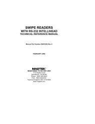
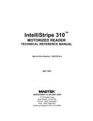
<strong>USB</strong> <strong>HID</strong> <strong>Swipe</strong> <strong>Reader</strong>SPECIFICATIONSTable 1-1 lists the specifications for the <strong>USB</strong> <strong>Swipe</strong> <strong>Reader</strong>. Figure 1-2 shows the dimensionsfor the standard product.Table 1-1. Specifications<strong>Reference</strong> StandardsPower InputRecording MethodMessage FormatCard SpeedCurrentMTBFNormal ModeSuspend ModeISO 7810 and ISO 7811/AAMVA*5V From <strong>USB</strong> busTwo-frequency coherent phase (F2F)ASCII3 to 60 ips (7.62 – 152.4 cm/s)ELECTRICAL15 mA200 uA1.0 E06 Hrs based on Mil-217MECHANICALSizeLength3.94” (100.0mm)Width1.28” (32.5mm)Height1.23” (31.3mm)Weight 4.5 oz. (127.57 g)Cable lengthConnector6 ft. (1.8m)<strong>USB</strong> Type A plugENVIRONMENTALTemperatureOperating -40 o C to 70 o C (-40 o F to 158 o F)Storage -40 o C to 70 o C (-40 o F to 158 o F)HumidityOperating 10% to 90% noncondensingStorage 10% to 90% noncondensingAltitudeOperating 0-10,000 ft. (0-3048 m.)Storage 0-50,000 ft. (0-15240 m.)* ISO (International Standards Organization) and AAMVA (AmericanAssociation of Motor Vehicle Administrators).4
Section 1. Features and SpecificationsFigure 1-2. Dimensions5
<strong>USB</strong> <strong>HID</strong> <strong>Swipe</strong> <strong>Reader</strong>6
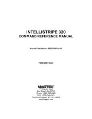
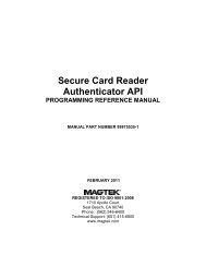
SECTION 2. INSTALLATIONThis section describes the cable connection, the Windows Plug and Play Setup, and the physicalmounting of the unit.<strong>USB</strong> CONNECTIONConnect the <strong>USB</strong> cable to a <strong>USB</strong> port on the host. The <strong>Reader</strong>, LED Indicator, and pin numbersfor the 4-pin connector are shown in Figure 2-1.Figure 2-1. <strong>Reader</strong> Cable and ConnectorPin numbers and signal descriptions for the cable shown in the illustration are listed in Table 2-1.Table 2-1. 4-Pin ConnectorPin Number Signal Cable Color1 VBUS Red2 -Data White3 +Data Green4 Ground Black7
<strong>USB</strong> <strong>HID</strong> <strong>Swipe</strong> <strong>Reader</strong>10
SECTION 3. OPERATIONThis section describes the LED Indicator and Card Read.LED INDICATORThe LED indicator will be either off, red, or green. When the device is not powered, the LEDwill be off. When the device is first plugged in, the LED will be red. As soon as the device isplugged in, the host will try to enumerate the device. Once the device is enumerated the LEDwill turn green indicating that the device is ready for use. When a card is being swiped, the LEDwill turn off temporarily until the swipe is completed. If there are no errors after decoding thecard data then the LED will turn green. If there are any errors after decoding the card data, theLED will turn red for approximately two seconds to indicate that an error occurred and then turngreen. Anytime the host puts the device into suspend mode, the LED will turn off. Once thehost takes the device out of suspend mode, the LED will return to the state it was in prior toentering suspend mode.CARD READA card may be swiped through the <strong>Reader</strong> slot when the LED is green.When using a <strong>USB</strong> <strong>HID</strong> <strong>Swipe</strong> <strong>Reader</strong> (with a single head), the magnetic stripe must face towardthe front (the side with the LED) and may be swiped in either direction.When using a <strong>USB</strong> <strong>HID</strong> Sure<strong>Swipe</strong> reader (with dual heads), the magnetic stripe can face towardthe front or the back, and may be swiped in either direction.If there is data encoded on the card, the reader will attempt to decode the data and then send theresults to the host via a <strong>USB</strong> <strong>HID</strong> input report. After the results are sent to the host, the devicewill be ready to read the next card.11
<strong>USB</strong> <strong>HID</strong> <strong>Swipe</strong> <strong>Reader</strong>12
<strong>USB</strong> <strong>HID</strong> <strong>Swipe</strong> <strong>Reader</strong>following table. The usage types are also listed. These usage types are defined in the <strong>HID</strong>Usage Tables document.Magnetic Stripe <strong>Reader</strong> usage page 0xff00:14Usage ID(Hex)Usage NameUsageTypeReportType1 Decoding reader device Collection None20 Track 1 decode status Data Input21 Track 2 decode status Data Input22 Track 3 decode status Data Input28 Track 1 data length Data Input29 Track 2 data length Data Input2A Track 3 data length Data Input30 Track 1 data Data Input31 Track 2 data Data Input32 Track 3 data Data Input38 Card encode type Data Input20 Command message Data FeatureREPORT DESCRIPTORThe <strong>HID</strong> report descriptor is structured as follows:ItemUsage Page (Magnetic Stripe <strong>Reader</strong>)Value(Hex)06 00 FFUsage (Decoding reader device) 09 01Collection (Application) A1 01Logical Minimum (0) 15 00Logical Maximum (255) 26 FF 00Report Size (8) 75 08Usage (Track 1 decode status) 09 20Usage (Track 2 decode status) 09 21Usage (Track 3 decode status) 09 22Usage (Track 1 data length) 09 28Usage (Track 2 data length) 09 29Usage (Track 3 data length)09 2AUsage (Card encode type) 09 38Report Count (7) 95 07Input (Data, Variable, Absolute, Bit Field) 81 02Usage (Track 1 data) 09 30Report Count (110)95 6EInput (Data, Variable, Absolute, Buffered Bytes) 82 02 01Usage (Track 2 data) 09 31Report Count (110)95 6EInput (Data, Variable, Absolute, Buffered Bytes) 82 02 01Usage (Track 3 data) 09 32Report Count (110)95 6EInput (Data, Variable, Absolute, Buffered Bytes) 82 02 01
Section 4. <strong>USB</strong> CommunicationsCARD DATAItemValue(Hex)Usage (Command message) 09 20Report Count (24) 95 18Feature (Data, Variable, Absolute, Buffered Bytes) B2 02 01End CollectionC0Card data is only sent to the host on the Interrupt In pipe using an Input Report. The device willsend only one Input Report per card swipe. If the host requests data from the device when nodata is available, the device will send a Nak to the host to indicate that it has nothing to send.When a card is swiped, the Input Report will be sent even if the data is not decodable. Thefollowing table shows how the input report is structured.Offset Usage Name0 Track 1 decode status1 Track 2 decode status2 Track 3 decode status3 Track 1 data length4 Track 2 data length5 Track 3 data length6 Card encode type7 – 116 Track 1 data117 – 226 Track 2 data227 - 336 Track 3 dataTRACK 1 DECODE STAT<strong>USB</strong>its 7-1 0Value Reserved ErrorThis is a one-byte value, which indicates the status of decoding track 1. Bit position zeroindicates if there was an error decoding track 1 if the bit is set to one. If it is zero, then no erroroccurred. If a track has data on it that is not noise, and it is not decodable, then a decode error isindicated. If a decode error is indicated, the corresponding track data length value for the trackthat has the error will be set to zero and no valid track data will be supplied.TRACK 2 DECODE STAT<strong>USB</strong>its 7-1 0Value Reserved ErrorThis is a one-byte value, which indicates the status of decoding track 2. Bit position zeroindicates if there was an error decoding track 2 if this bit is set to one. If it is zero, then no erroroccurred. If a track has data on it that is not noise, and it is not decodable, then a decode error isindicated. If a decode error is indicated, the corresponding track data length value for the trackthat has the error will be set to zero and no valid track data will be supplied.15
<strong>USB</strong> <strong>HID</strong> <strong>Swipe</strong> <strong>Reader</strong>TRACK 3 DECODE STAT<strong>USB</strong>its 7-1 0Value Reserved ErrorThis is a one-byte value, which indicates the status of decoding track 3. Bit position zeroindicates if there was an error decoding track 3 if this bit is set to one. If it is zero, then no erroroccurred. If a track has data on it that is not noise, and it is not decodable, then a decode error isindicated. If a decode error is indicated, the corresponding track data length value for the trackthat has the error will be set to zero and no valid track data will be supplied.TRACK 1 DATA LENGTHThis one-byte value indicates how many bytes of decoded card data are in the track 1 data field.This value will be zero if there was no data on the track or if there was an error decoding thetrack.TRACK 2 DATA LENGTHThis one-byte value indicates how many bytes of decoded card data are in the track 2 data field.This value will be zero if there was no data on the track or if there was an error decoding thetrack.TRACK 3 DATA LENGTHThis one-byte value indicates how many bytes of decoded card data are in the track 3 data field.This value will be zero if there was no data on the track or if there was an error decoding thetrack.CARD ENCODE TYPEThis one-byte value indicates the type of encoding that was found on the card. The followingtable defines the possible values.Value Encode Type Description0 ISO/ABA ISO/ABA encode format1 AAMVA AAMVA encode format2 CADL CADL encode format. Note that (after the June 2005 update)this reader can only read track 2 for this format. It cannot readtracks 1 and 3. However, this format is obsolete. There shouldno longer be any cards in circulation that use this format.California is now using the AAMVA format.3 Blank The card is blank.4 Other The card has a non-standard encode format. For example,ISO/ABA track 1 format on track 2.5 Undetermined The card encode type could not be determined because notracks could be decoded.6 None No decode has occurred. This type occurs if no magnetic stripedata has been acquired since the data has been cleared orsince the device was powered on. This device only sends anInput report when a card has been swiped so this value willnever occur.16
Section 4. <strong>USB</strong> CommunicationsTRACK DATAIf decodable track data exists for a given track, it is located in the track data field thatcorresponds to the track number. The length of each track data field is fixed at 110 bytes, but thelength of valid data in each field is determined by the track data length field that corresponds tothe track number. Track data located in positions greater than the track data length fieldindicates are undefined and should be ignored. The <strong>HID</strong> specification requires that reports befixed in size, but the number of bytes encoded on a card may vary. Therefore, the Input Reportalways contains the maximum amount of bytes that can be encoded on the card and the numberof valid bytes in each track is indicated by the track data length field. The track data is decodedand converted to ASCII. The track data includes all data starting with the start sentinel andending with the end sentinel.TRACK 1 DATAThis field contains the decoded track data for track 1.TRACK 2 DATAThis field contains the decoded track data for track 2.TRACK 3 DATAThis field contains the decoded track data for track 3.COMMANDSMost host applications do not need to send commands to the device. Most host applications onlyneed to obtain card data from the device as described previously in this section. This section ofthe manual can be ignored by anyone who does not need to send commands to the device.Command requests and responses are sent to and received from the device using feature reports.Command requests are sent to the device using the <strong>HID</strong> class specific request Set Report. Theresponse to a command is retrieved from the device using the <strong>HID</strong> class specific request GetReport. These requests are sent over the default control pipe. When a command request is sent,the device will Nak the Status stage of the Set Report request until the command is completed.This insures that, as soon as the Set Report request is completed, the Get Report request can besent to get the command response. The usage ID for the command message was shownpreviously in the Usage Table.The following table shows how the feature report is structured for command requests:OffsetField Name0 Command Number1 Data Length2 – 23 DataThe following table shows how the feature report is structured for command responses.OffsetField Name0 Result Code1 Data Length2 – 23 Data17
<strong>USB</strong> <strong>HID</strong> <strong>Swipe</strong> <strong>Reader</strong>COMMAND NUMBERThis one-byte field contains the value of the requested command number. The following tablelists all the existing commands.Value Command Number Description0 GET PROPERTY Gets a property from the device1 SET PROPERTY Sets a property in the device2 RESET DEVICE Resets the deviceDATA LENGTHThis one-byte field contains the length of the valid data contained in the Data field.DATAThis multi-byte field contains command data if any. Note that the length of this field is fixed at22 bytes. Valid data should be placed in the field starting at offset 2. Any remaining data afterthe valid data should be set to zero. This entire field must always be set even if there is no validdata. The <strong>HID</strong> specification requires that Reports be fixed in length. Command data may varyin length. Therefore, the Report should be filled with zeros after the valid data.RESULT CODEThis one-byte field contains the value of the result code. There are two types of result codes:generic result codes and command-specific result codes. Generic result codes always have themost significant bit set to zero. Generic result codes have the same meaning for all commandsand can be used by any command. Command-specific result codes always have the mostsignificant bit set to one. Command-specific result codes are defined by the command that usesthem. The same code can have different meanings for different commands. Command-specificresult codes are defined in the documentation for the command that uses them. Generic resultcodes are defined in the following table.Value Result Code Description0 SUCCESS The command completed successfully.1 FAILURE The command failed.2 BAD PARAMETER The command failed due to a badparameter or command syntax error.GET AND SET PROPERTY COMMANDSThe Get Property command gets a property from the device. The Get Property commandnumber is 0.The Set Property command sets a property in the device. The Set Property command numberis 1.The Get and Set Property command data fields for the requests and responses are structured asfollows:18
Section 4. <strong>USB</strong> CommunicationsGet Property Request Data:Data Offset Value0 Property IDGet Property Response Data:Data Offset Value0 – n Property ValueSet Property Request Data:Data Offset Value0 Property ID1 – n Property ValueSet Property Response Data:NoneThe result codes for the Get and Set Property commands can be any of the codes list in thegeneric result code table.Property ID is a one-byte field that contains a value that identifies the property. The followingtable lists all the current property ID values:Value(Hex)Property IDDescription00 SOFTWARE ID The device’s software identifier01 SERIAL NUM The device’s serial number02 POLLING INTERVAL The interrupt pipe’s polling interval03 MAX PACKET SIZE The interrupt pipe’s packet size04 TRACK ID ENABLE Allows tracks to be disabled16 INTERFACE TYPE Type of <strong>USB</strong> interface52 HOST POLL TIMEOUT Allows <strong>USB</strong> poll timeout to be adjustedThe Property Value is a multiple-byte field that contains the value of the property. The numberof bytes in this field depends on the type of property and the length of the property. Thefollowing table lists all of the property types and describes them.Property TypeByteStringDescriptionThis is a one-byte value. The valid values depend on the property.This is a multiple-byte ASCII string. Its length can be zero to amaximum length that depends on the property. The value andlength of the string does not include a terminating NUL character.SOFTWARE ID PROPERTYProperty ID: 0x00Property Type: StringLength: Fixed at 11 bytesGet Property: YesSet Property: NoDescription: This is an 11-byte read only property that identifies the software part numberand version for the device. The first 8 bytes represent the part number and the19
<strong>USB</strong> <strong>HID</strong> <strong>Swipe</strong> <strong>Reader</strong>20last 3 bytes represent the version. For example this string might be“21042812D01”. Examples follow:Example Get SOFTWARE ID property Request (Hex):Cmd Num Data Len Prp ID00 01 00Example Get SOFTWARE ID property Response (Hex):Result Code Data Len Prp Value00 01 32 31 30 34 32 38 31 32 44 30 31SERIAL NUM PROPERTYProperty ID: 0x01Property Type: StringLength: 0 – 15 bytesGet Property: YesSet Property: YesDefault Value: The default value is no string with a length of zero.Description: The value is an ASCII string that represents the device’s serial number. Thisstring can be 0 – 15 bytes long. The value of this property, if any, will be sentto the host when the host requests the <strong>USB</strong> string descriptor.This property is stored in non-volatile memory, so it will persist when the unitis power cycled. When this property is changed, the unit must be reset (seeCommand Number 2) or power cycled to have these changes take effect.Example Set SERIAL NUM property Request (Hex):Cmd Num Data Len Prp ID Prp Value01 04 01 31 32 33Example Set SERIAL NUM property Response (Hex):Result Code Data Len Data00 00Example Get SERIAL NUM property Request (Hex):Cmd Num Data Len Prp ID00 01 01Example Get SERIAL NUM property Response (Hex):Result Code Data Len Prp Value00 03 31 32 33POLLING INTERVAL PROPERTYProperty ID: 0x02Property Type: ByteLength: 1 byteGet Property: YesSet Property: YesDefault Value: 10
Section 4. <strong>USB</strong> CommunicationsDescription:The value is a byte that represents the devices polling interval for the InterruptIn Endpoint. The value can be set in the range of 1 – 255 and has units ofmilliseconds. The polling interval tells the host how often to poll the devicefor card data packets. For example, if the polling interval is set to 10, the hostwill poll the device for card data packets every 10ms. This property can beused to speed up or slow down the time it takes to send card data to the host.The trade-off is that speeding up the card data transfer rate increases the <strong>USB</strong>bus bandwidth used by the device, and slowing down the card data transferrate decreases the <strong>USB</strong> bus bandwidth used by the device. The value of thisproperty, if any, will be sent to the host when the host requests the device’s<strong>USB</strong> endpoint descriptor.This property is stored in non-volatile memory, so it will persist when the unitis power cycled. When this property is changed, the unit must be reset (seeCommand Number 2) or power cycled to have these changes take effect.Example Set POLLING INTERVAL property Request (Hex):Cmd Num Data Len Prp ID Prp Value01 02 02 0AExample Set POLLING INTERVAL property Response (Hex):Result Code Data Len Data00 00Example Get POLLING INTERVAL property Request (Hex):Cmd Num Data Len Prp ID00 01 02Example Get POLLING INTERVAL property Response (Hex):Result Code Data Len Prp Value00 01 0AMAX PACKET SIZE PROPERTYProperty ID: 0x03Property Type: ByteLength: 1 byteGet Property: YesSet Property: YesDefault Value: 8Description: The value is a byte that represents the devices maximum packet size for theInterrupt In Endpoint. The value can be set in the range of 1 – 64 and hasunits of bytes. The maximum packet size tells the host the maximum size ofthe Interrupt In Endpoint packets. For example, if the maximum packet size isset to 8, the device will send <strong>HID</strong> reports in multiple packets of 8 bytes eachor less for the last packet of the report. This property can be used to speed upor slow down the time it takes to send card data to the host. Larger packetsizes speed up communications and smaller packet sizes slow downcommunications. The trade-off is that speeding up the card data transfer rateincreases the <strong>USB</strong> bus bandwidth used by the device, and slowing down the21
<strong>USB</strong> <strong>HID</strong> <strong>Swipe</strong> <strong>Reader</strong>card data transfer rate decreases the <strong>USB</strong> bus bandwidth used by the device.The value of this property will be sent to the host when the host requests thedevice’s <strong>USB</strong> endpoint descriptor.This property is stored in non-volatile memory, so it will persist when the unitis power cycled. When this property is changed, the unit must be reset (seeCommand Number 2) or power cycled to have these changes take effect.Example Set MAX PACKET SIZE property Request (Hex):Cmd Num Data Len Prp ID Prp Value01 02 03 08Example Set MAX PACKET SIZE property Response (Hex):Result Code Data Len Data00 00Example Get MAX PACKET SIZE property Request (Hex):Cmd Num Data Len Prp ID00 01 03Example Get MAX PACKET SIZE property Response (Hex):Result Code Data Len Prp Value00 01 08TRACK ID ENABLE PROPERTYProperty ID: 0x04Property Type: ByteLength: 1 byteGet Property: YesSet Property: YesDefault Value: 95 (hex)Description: This property is defined as follows:id 0 T 3 T 3 T 2 T 2 T 1 T 1IdT #0 – Decodes standard ISO/ABA cards only1 – Decodes AAMV and 7-bit cards also00 – Track Disabled01 – Track Enabled10 – Track Enabled/Required (Error if blank)This property is stored in non-volatile memory, so it will persist when the unit ispower cycled. When this property is changed, the unit must be reset (seeCommand Number 2) or power cycled to have these changes take effect.22
Section 4. <strong>USB</strong> CommunicationsExample Set TRACK ID ENABLE property Request (Hex):Cmd Num Data Len Prp ID Prp Value01 02 04 95Example Set TRACK ID ENABLE property Response (Hex):Result Code Data Len Data00 00Example Get TRACK ID ENABLE property Request (Hex):Cmd Num Data Len Prp ID00 01 04Example Get TRACK ID ENABLE property Response (Hex):Result Code Data Len Prp Value00 01 95INTERFACE TYPE PROPERTYProperty ID: 0x10Property Type: ByteLength: 1 byteGet Property: YesSet Property: YesDefault Value: 0 (<strong>HID</strong>)Description: The value is a byte that represents the devices interface type. The value canbe set to 0 for the <strong>HID</strong> interface or to 1 for the keyboard emulation interface.When the value is set to 0 (<strong>HID</strong>) the device will behave as described in the<strong>HID</strong> manual. When the value is set to 1 (keyboard emulation) the device willbehave as described in the keyboard emulation manual. This property shouldbe the first property changed because it affects which other properties areavailable. After this property is changed, the device should be power cycledbefore changing any other properties.This property is stored in non-volatile memory, so it will persist when the unit ispower cycled. When this property is changed, the unit must be reset (seeCommand Number 2) or power cycled to have these changes take effect.Example Set INTERFACE TYPE property Request (Hex):Cmd Num Data Len Prp ID Prp Value01 02 10 01Example Set INTERFACE TYPE property Response (Hex):Result Code Data Len Data00 00Example Get INTERFACE TYPE property Request (Hex):Cmd Num Data Len Prp ID00 01 1023
<strong>USB</strong> <strong>HID</strong> <strong>Swipe</strong> <strong>Reader</strong>Example Get INTERFACE TYPE property Response (Hex):Result Code Data Len Prp Value00 01 00HOST POLL TIMEOUT PROPERTYProperty ID: 0x52Property Type: ByteLength: 1 byteGet Property: YesSet Property: YesDefault Value: 0x02 (2 seconds)Description: This property can be used to adjust the device’s host poll timeout. Theproperty can be set to 0 to disable the timeout or it can be set to a value in therange of 1 to 60 seconds.The host poll timeout was added around the year 2010 because if a <strong>USB</strong>suspend occurred while the reader was in the middle of transmitting card datato the host, the reader would no longer be able to read cards until powercycled. It was given a fixed value of 2 seconds. If a <strong>USB</strong> suspend nowoccurred while the reader was transmitting card data, this timeout would occurand the remainder of the card data would be discarded and the reader wouldbe ready to read the next card once it got a <strong>USB</strong> resume signal. Getting a<strong>USB</strong> suspend while transmitting card data is not an event that would beexpected to occur under normal operating conditions, however a customer wasseeing this occur due to abnormal <strong>USB</strong> bus activity from other devices on thebus.Around the year 2012, starting with firmware part number 21042886 RevisionC.01, this timeout was made adjustable with this property so that it could bedisabled or adjusted. This property was added because some printers, madeby HP and used as a host in this application, were occasionally ceasing to pollthe reader for more than two seconds which would cause a timeout to occurwhich would in turn cause the host application to have problems. The timeoutwas disabled to resolve this problem. The printer was not behaving properlyin this case. This problem would not be expected to occur on an error free<strong>USB</strong> Bus.Not all readers contain this timeout and not all readers contain this property toadjust it.This property is stored in non-volatile memory, so it will persist when the unit ispower cycled. When this property is changed, the unit must be reset (seeCommand Number 2) or power cycled to have these changes take effect.Example Set HOST POLL TIMEOUT property Request (Hex):Cmd Num Data Len Prp ID Prp Value01 02 52 0224
Section 4. <strong>USB</strong> CommunicationsExample Set HOST POLL TIMEOUT property Response (Hex):Result Code Data Len Data00 00Example Get HOST POLL TIMEOUT property Request (Hex):Cmd Num Data Len Prp ID00 01 52Example Get HOST POLL TIMEOUT property Response (Hex):Result Code Data Len Prp Value00 01 02RESET DEVICE COMMANDCommand number: 0x02Description: This command is used to reset the device. This command can be used tomake previously changed properties take affect without having to unplug andthen plug in the device. When the device resets, it automatically does a <strong>USB</strong>detach followed by an attach. After the host sends this command to the deviceit should close the <strong>USB</strong> port, wait a few seconds for the operating system tohandle the device detach followed by the attach and then re-open the <strong>USB</strong>port before trying to communicate further with the device.Data structure: No data is sent with this commandResult codes: 0 (success)Example Request (Hex):Cmd Num Data Len Data02 00Example Response (Hex):Result Code Data Len Data00 0025
<strong>USB</strong> <strong>HID</strong> <strong>Swipe</strong> <strong>Reader</strong>26
SECTION 5. DEMO PROGRAMThe demo program, which is written in Visual Basic, can be used to do the following:• Read cards from the device and view the card data• Send command requests to the device and view the command responses• Guide application developers in their application development by providing examples, insource code, of how to properly communicate with the device using the standard WindowsAPIsThe part numbers for the demo program can be found in this document in Section 1 underAccessories.INSTALLATIONTo install the demo program, run the setup.exe file and follow the instructions given on thescreen.OPERATIONTo operate the demo program perform the following steps:• Attach the device into a <strong>USB</strong> port on the host.• If this is the first time the device has been plugged into the host, follow the instructions onthe screen for installing the Windows <strong>HID</strong> device driver. This is explained in more detail inthe installation section of this document.• Run the demo program.• To read cards and view the card data, click on the Read Cards button and swipe a card whenprompted to do so.• When finished reading cards, close the dialog box.• To send commands to the device, click on the send commands button.• Enter a command in the Message edit box. All data entered should be in hexadecimal byteswith a space between each byte. Enter the command number followed by the command dataif there is any. The application will automatically calculate and send the command datalength for you. For example, to send the GET PROPERTY command for propertySOFTWARE ID enter 00 00.• Press Enter or click on Send message to send the command and receive the result.• The command request and the command result will be displayed in the CommunicationsDialog edit box.• The Clear Dialog button clears the Communication Dialog edit box.27
<strong>USB</strong> <strong>HID</strong> <strong>Swipe</strong> <strong>Reader</strong>SOURCE CODESource code is included with the demo program. It can be used as a guide for applicationdevelopment. It is described in detail, with comments, to assist developers. The book <strong>USB</strong>Complete by Jan Axelson is also a good guide for application developers, especially the chapteron Human Interface Device Host Applications (see “<strong>Reference</strong> Documents” in Section 1).28