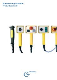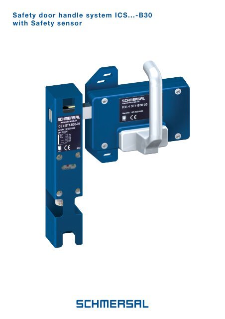
Safety door handle system ICS...-B30 with Safety sensor - Schmersal
Safety door handle system ICS...-B30 with Safety sensor - Schmersal
Safety door handle system ICS...-B30 with Safety sensor - Schmersal

You also want an ePaper? Increase the reach of your titles
YUMPU automatically turns print PDFs into web optimized ePapers that Google loves.
<strong>Safety</strong> <strong>door</strong> <strong>handle</strong> <strong>system</strong> <strong>ICS</strong>...-<strong>B30</strong><strong>with</strong> <strong>Safety</strong> <strong>sensor</strong>
Principle of operationThe <strong>ICS</strong> safety <strong>sensor</strong>operates according to theidentification principle inconjunction <strong>with</strong> its individuallycoded <strong>ICS</strong>-<strong>B30</strong>actuator. In the insertedposition the <strong>ICS</strong>-<strong>B30</strong>actuator latches and theenabling signal to thesafety circuit only occursin this position. Theevaluation of the safetycode in the safety <strong>sensor</strong>takes place on twochannels. Both channelsprovide mutual monitoringof each other. Each channelhas an output <strong>with</strong>two output transistors.Through this monitoringof the outputs, a connectionbetween the outputand the supply isdetected and switch-on isprevented. A groundconnection and a lowvoltage on an output leadto both outputs switchingoff.The evaluation device istypically a safety PLC ora safety <strong>door</strong> monitor.This device usuallyprovides the voltagesupply for the safety<strong>sensor</strong> and its twooutputs. The supply forthe outputs can includeclock signals for checkingthe connection leads forbreakage and short circuit.FunctionThe enabling signal to thesafety circuit is onlyissued when the <strong>ICS</strong>-<strong>B30</strong>actuator is located <strong>with</strong>inthe safety <strong>sensor</strong> and islatched. The two greenindicators (CH1 + CH2)on the <strong>ICS</strong> safety <strong>sensor</strong>then light. The hysteresisrange can be discernedby the flickering of thered indicator (ERR) <strong>with</strong>the green indicatorscontinuing to light (theoutputs in this caseremain switched on andexhibit typical hysteresisbehaviour). After thishysteresis range is left,the two green indicatorsgo out and the redindicator lights.From the status of thelight emitting diodes,information about thestatus of the <strong>ICS</strong>(damped/undamped) andabout possible faultsituations can be derived.Some possiblecombinations are shownbelow:LED CH1LED ERRLED CH2Switching condition LED CH1 LED CH2 LED ERR(green) (green) (red)Normal operationSensor damped ON ON OFFSensor undamped OFF OFF ONHysteresis range ON ON flashesFault conditionCH1 defective OFF ON ONCH2 defective ON OFF ONShort circuit CH1* flashes flashes ONShort circuit CH2* flashes flashes ON* <strong>with</strong> respect to supply voltage (L+ or L-)<strong>Safety</strong> <strong>sensor</strong>LEvaluationChannel 1(Ch1)OutputStage 1LATransponderActuatorReadingheadEvaluationChannel 2(Ch2)OutputStage 2LALThis block diagram shows the basic configuration of the <strong>ICS</strong> <strong>with</strong> its two-channel structure.3
<strong>Safety</strong> <strong>door</strong> <strong>handle</strong> <strong>system</strong> -<strong>B30</strong> <strong>with</strong> individually coded safety <strong>sensor</strong>Series <strong>ICS</strong>… ST1-<strong>B30</strong>-08Door hinged to the left <strong>with</strong>out emergency <strong>handle</strong>Features• Metallic enclosure <strong>with</strong> individuallycoded <strong>ICS</strong> safety <strong>sensor</strong>• Control Category 3 or 4• <strong>ICS</strong>-<strong>B30</strong> actuator includingmounting plate for simple fitting• Shearing force 67,000 N• Side offset ± 5 mm• Door <strong>handle</strong> latches inclosed position• ST1 plug version• Lockout tag against unintentionalclosure available (not included)<strong>ICS</strong>3 …: x = 165; Y = 189<strong>ICS</strong>4 …: x = 223; Y = 247Contacts/Switch travelDoor hinged to the left<strong>with</strong>out emergency <strong>handle</strong>1 NC/1 NCL1L2A1A2Category 3Category 4<strong>ICS</strong>3 ST1-<strong>B30</strong>-08<strong>ICS</strong>4 ST1-<strong>B30</strong>-08NoteContacts shown <strong>with</strong> actuator inserted and in voltage-free state.7
<strong>Safety</strong> <strong>door</strong> <strong>handle</strong> <strong>system</strong> -<strong>B30</strong> <strong>with</strong> individually coded safety <strong>sensor</strong>AccessoriesMounting plate MP <strong>ICS</strong>-<strong>B30</strong>• Mounting plate for the <strong>ICS</strong>-<strong>B30</strong> actuator• Aluminium• Plate thickness 15 mm• With <strong>ICS</strong>-<strong>B30</strong> actuator factory-fitted• Included in supplied itemsMounting plate MP TG-02• Mounting plate for the emergency <strong>handle</strong>• For simple fitting of the AZ/AZM 415-<strong>B30</strong>emergency <strong>handle</strong>• Plate thickness 5 mm• With emergency <strong>handle</strong> factory-fitted• Included in supplied items154,5132112R445°3078,5M52086,550¤1627,545 3324501175<strong>ICS</strong> Cover• For covering the plug on the enclosure• Not included in supplied items8
<strong>Safety</strong> <strong>door</strong> <strong>handle</strong> <strong>system</strong> -<strong>B30</strong> <strong>with</strong> individually coded safety <strong>sensor</strong>AccessoriesLockout tag SZ 415-1/-2• For protection against unintentional closure,e.g. during installation work• For <strong>system</strong>s where visibility is restricted• Prevents operation of the switch• Suitable for mounting inside and outsideof hazard area• SZ 415-1: for AZ/AZM 415-<strong>B30</strong>-06,AZ/AZM 415-<strong>B30</strong>-08,• SZ 415-2: for AZ/AZM 415-<strong>B30</strong>-05,AZ/AZM 415-<strong>B30</strong>-07,• Version SZ 415-1 is shown,version SZ 415-2 has mirror-image design• Not included in supplied itemsConnector plug <strong>ICS</strong>4 ST1• Straight mating connector• 6-pole• Can be wired as required• Wire cross-section: 6 x 0.75 mm 2• Not included in supplied itemsØ2651Connector plug <strong>ICS</strong>3 ST1• Straight mating connector• 8-pole• M12 Euro-plug• Length of lead 5 m• Not included in supplied items9
<strong>Safety</strong> <strong>door</strong> <strong>handle</strong> <strong>system</strong> -<strong>B30</strong> <strong>with</strong> individually coded safety <strong>sensor</strong>Technical Data<strong>ICS</strong> 3 ST1-<strong>B30</strong>..<strong>ICS</strong> 4 ST1-<strong>B30</strong>..Regulations:IEC/EN 60947-5-3 PDF/MControl Category: 3 accord. to EN 954-1 4 accord. to EN 954-1Enclosure:Metal enclosureType of protection: IP 65 IP 67Protective insulation:XProtection class: Protection Class II accord. to IEC 60947-1Type of connection: Connector plug, 8-pole, Euro-plug, M12 Connector plug, 6-pole, M23 x 1 (Conninvers RC)Operating principle:TransponderSwitching distance, hysteresis: 13 ± 5 mm, < 15%Switch status indicators:LED 2 x identification (gn); 1 x fault (rd)Input voltage U L1,L2 : 12 ... 24 ... 30 VDC 12 ... 24 ... 30 VDC,Clock: Low pulse < 100 µsClock: Pulse: 1 ... 5 ms; space: 1...5 msOutput voltage U A1,A2 : Typ. < U L1,L2 – 1.75 V (100 mA) U L1,L2 – 5 V < U A1,A2 < U L1,L2 – 1 VOutput current:< 400 mA per outputOutputs:2 semiconductor outputs, current sourcingResponse time: > 80 ms, typ. 120 ms > 150 ms, typ. 185 msDecay time: < 50 ms, typ. 10 ms > 75 ms, typ. 100 msMax. perm. lead length:300 mOperating voltage U L+ :15 ... 24 ... 30 VDCOperating current I e :< 90 mAAmbient temperature: – 30 °C … + 60 °CShock resistance:30 g / 11 msVibration resistance:10 ... 55 Hz, amplitude 1 mm10
<strong>Safety</strong> <strong>door</strong> <strong>handle</strong> <strong>system</strong> -<strong>B30</strong> <strong>with</strong> individually coded safety <strong>sensor</strong>Circuit exampleChannel 1 Channel 2<strong>Safety</strong> monitoring moduleFeaturesProduct selectionDescription:• Safeguarding a guard <strong>door</strong><strong>Safety</strong> <strong>door</strong> <strong>handle</strong> <strong>system</strong>:<strong>ICS</strong> Series<strong>Safety</strong> circuit:• Two-channel<strong>Safety</strong> monitoring modules:Protect SeriesInput circuit: • Control Category 3accord. to EN 954-1Note:The circuit example is shown forthe guard device closed and inthe voltage-free state.Info:You will find further safety monitoringmodules and technical details in thecatalogue "<strong>Safety</strong> relay modulesProtect SRB's"11
K.A. <strong>Schmersal</strong> GmbHIndustrielle Sicherheitsschalt<strong>system</strong>eMöddinghofe 30D-42279 WuppertalPostfach 24 02 63D-42232 WuppertalTelefon +49 - (0)2 02 - 64 74 - 0Telefax +49 - (0)2 02 - 64 74 - 1 00E-Mail info@schmersal.deInternet http://www.schmersal.com2.000/L.D./03.2003/Teile-Nr. 1171605