Federal Aviation Administration National Aeronautical Navigation ...
Federal Aviation Administration National Aeronautical Navigation ...
Federal Aviation Administration National Aeronautical Navigation ...

Create successful ePaper yourself
Turn your PDF publications into a flip-book with our unique Google optimized e-Paper software.
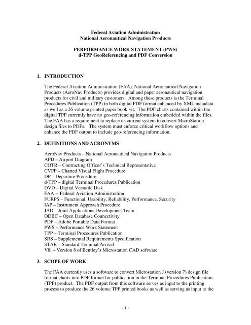
<strong>Federal</strong> <strong>Aviation</strong> <strong>Administration</strong><strong>National</strong> <strong>Aeronautical</strong> <strong>Navigation</strong> ProductsPERFORMANCE WORK STATEMENT (PWS)d-TPP GeoReferencing and PDF Conversion1. INTRODUCTIONThe <strong>Federal</strong> <strong>Aviation</strong> <strong>Administration</strong> (FAA), <strong>National</strong> <strong>Aeronautical</strong> <strong>Navigation</strong>Products (AeroNav Products) provides digital and paper aeronautical navigationproducts for civil and military customers. Among these products is the TerminalProcedures Publication (TPP) in both digital PDF format enhanced by XML metadataas well as a 26 volume printed paper book set. The PDF charts contained within thedigital TPP currently have no geo-referencing information embedded within the files.The FAA has a requirement to replace its current system to convert MicroStationdesign files to PDFs. The system must enforce critical workflow options andenhance the PDF output to include geo-referencing information.2. DEFINITIONS AND ACRONYMSAeroNav Products – <strong>National</strong> <strong>Aeronautical</strong> <strong>Navigation</strong> ProductsAPD – Airport DiagramCOTR – Contracting Officer’s Technical RepresentativeCVFP – Charted Visual Flight ProcedureDP – Departure Procedured-TPP – digital Terminal Procedures PublicationDVD – Digital Versatile DiskFAA -- <strong>Federal</strong> <strong>Aviation</strong> <strong>Administration</strong>FURPS – Functional, Usability, Reliability, Performance, SecurityIAP – Instrument Approach ProcedureJAD – Joint Applications Development TeamODBC – Open Database ConnectivityPDF – Adobe Portable Data FormatPWS – Performance Work StatementTPP – Terminal Procedures PublicationSRS – Supplemental Requirements SpecificationSTAR – Standard Terminal ArrivalV8i – Version 8 of Bentley’s Microstation CAD software3. SCOPE OF WORKThe FAA currently uses a software to convert Microstation J (version 7) design fileformat charts into PDF format for publication in the Terminal Procedures Publication(TPP) product. The PDF output from this software serves as input to the printingprocess to produce the 26 volume TPP printed books as well as serving as input to the- 1 -
digital version of the TPP, the d-TPP. The software that produces these PDFs hasmany processing options that the FAA uses to control production and assure quality.The contractor shall replace the current FAA conversion software supporting thelatest version of Microstation (version V8i) and shall fulfill all the processing optionscontained within this PWS.The contractor shall lead a Joint Application Development (JAD) to create a set ofrequirements specifications to be used by the contractor in the development of a d-TPP PDF system. The contractor will manage and perform the tasks as definedwithin this PWS.Project Management deliverables include a Project Management Plan, WorkBreakdown Schedule (WBS), and Project Schedule. The government will reviewthese documents before any development work will be authorized.The contractor shall be responsible for the requirements analysis, system design,implementation, testing, and transition resulting in a production form of a softwarethat will convert Microstation V8i design files into PDF format that include georeferencinginformation. The resulting PDF files will be used for situationalawareness within GPS displays. The production software must satisfy various batchprocessing and shared properties controls detailed within the functional requirements.After the development and testing of the Design File to Georeferenced PDF software,the contractor shall implement a mass conversion and quality check of the FAA chartrepository into georeferenced PDF files. This output will serve as the final PDFproduct in support of both the digital and printed Terminal Procedures Publication(TPP) product.4. TASKS4.1. Task 1: Project Management4.1.1. Task 1, Subtask 1: Hold Kick-Off MeetingWithin 15 days of contract award, the contractor shall hold a kick-off meeting atthe FAA facility in Silver Spring MD. The purpose of this meeting and follow-ondiscussions, if needed, will be to define the following:1. Initial objectives, project milestones, and priorities2. Organizational structure3. Rules and processes for decision-making4. Participants and their roles5. Agree on structure for the JADa. Frequency of JADsb. Number of JADsc. Ground Rules4.1.2. Task 1, Subtask 2: Prepare Project Plan- 2 -
The contractor shall lead a Joint Applications Development team (JAD) to deliverthe documentation and subsequent reports for the requirements gathering of thesoftware. The team will be made up of FAA subject matter experts (SMEs) andFAA project support staff as well as a contractor facilitator, and requirementsexperts needed to conduct the meeting. The contractor shall be responsible forproviding agendas, facilitating and mediating the meetings, taking notes, anddistributing the meeting minutes following each meeting. Information gainedfrom the JAD meetings shall serve as the primary input for creating therequirements package deliverables defined below. Given the complexity of therequirements, a maximum of two (2) JAD meetings are deemed necessary togather all the requirements.4.2.2. Task 2, Subtask 2: Create System Requirements ArtifactsAccording to input received in the JAD team meetings the contractor must delivera Use Case Specification detailing each of the user interactions that are needed toproduce all the system requirements. The contactor must also produce aSupplemental Requirements Specification (SRS) to list functional, usability,reliability, performance, and security (FURPS) requirements.4.3. Task 3: Software Development4.3.1. Task 3, Subtask 1: System Design & ImplementationThe contractor shall design and implement software capable of fulfilling therequirements gathered in Task 2. System design shall be depicted in an informalarchitectural document including a use-case view, logical view, deployment view,implementation view, and a data view. The informal architecture document shallalso include all supported versions of reused software modules, supportedoperating systems, application server (if applicable), database engine, or any otherenvironmental software. The contractor is free to choose any system designcompliant with system requirements and ATO-IT Architectural and SystemConstraints The contractor should proceed through coding as part of this subtask.4.3.2. Task 3, Subtask 3: System TestingThe contractor shall develop a test plan based on Use Cases and SupplementalRequirements. The contractor shall rigorously test according to the test plan andpresent testing assessment report that details each iteration of tests, use casespassed and failed during the iteration, and actions taken to bring all use cases intocompliance with expected requirements. Factory testing should be consideredcomplete only after government review and acceptance of the test plan andtesting assessment report.4.4. Task 4: Data Delivery4.4.1. Task 4, Subtask 1: Mass Conversion of Geo-Referenced Charts- 4 -
Once the software is developed and all the functional requirements areimplemented, the contractor shall take delivery of all the Microstation design filesand associated geospatial metadata in the cartographic data repository of the FAAand perform a mass conversion of these files into georeferenced PDF format.This mass conversion must be timed to coincide with FAA production schedulesso as to be ready for publication as of the most current publication cycle.Although it is required by the software to be capable of design file to PDFconversion for non-geo-registered charts, these charts, as depicted in the table insection 5.1.2, will not be included in the mass conversion.4.4.2. Task 4, Subtask 2: Quality CheckAs part of the delivery of the mass converted georeferenced PDFs, the contractormust quality check the PDF repository. Quality must be maintained in twodifferent areas:1. Geo-Registration – The mass converted output PDFs must be tested andvariances reported for the positional accuracy of known points plotted onthe PDF output as compared to the spatial readout of the embeddedgeoreferenced information that was added to the PDF file by theconversion software.2. PDF Display – The mass converted output PDFs must conform to theaccepted FAA Terminal Procedures Publication (TPP) PDFs on a chart bychart basis. Individual converted PDFs must match published TPP chartsin terms of line weights of the entire drawing, colors of gray scale andcontour areas, font styles, the inclusion of reference files, overlayscreening opacity, and the general inclusion or exclusion of map features,informational text, and neatlines or other boxes. In addition to PDFsrepresenting charts, the textual pages (continuation pages, front matter,etc.) must also pass the same scrutiny.The contractor must maintain a defects log for discrepancies found in PDFscreated by the software. The charts where defects are found, the cause of theproblem, and the actions taken to correct the problem must be included in thereport for each defect found.Although non-geo-referenced charts are not to be converted though the massconversion process, the quality check process should include spot checks of DP,STAR, Charted Visual Flight Procedures, and textual pages that are notgeoreferenced in order to demonstrate the functionality for these charts.In the case of geo-registration tests, the contractor must coordinate with the FAAto obtain the feature information with known points that falls on each chart beingquality checked for geo-registration. The tolerance for acceptability of thevariance of the geo-referenced read out to the known positions of chart featuresmust be obtained by the contractor through discussions with FAA personnel.- 5 -
In addition to the design file to PDF conversion, the PDF to PDF processing mustpass scrutiny for output PDF sizing and text placement.In the case of PDF Display verification, the contractor shall verify the appearanceof the output PDF files through side by side verification of the correspondingexisting published TPP PDFs available on the latest cycle of the d-TPP DVDproduct from the FAA. The contractor must assure that the latest published copyof the d-TPP is used for side by side quality check.The quality check process implies a defect discovery and repair loop to correctthe software and release a new version with the latest correction. This loop mustcontinue during government acceptance testing as well.4.5. Task 5: Documentation4.5.1. Task 5, Subtask 1: Programmer DocumentationAlong with the delivery of the source code for the new software, the contractorshall provide documentation suitable for qualified, new, unfamiliar programmersto take up a maintenance task for the software. The documentation shall detaillow level design of the code and provide detail on all software modules includingmodule interface parameters, general description of methods, and any reusedlibraries incorporated into the code. Reused libraries shall include versionnumber. Software module (or class) interactions shall be detailed to depict thesequence of software messages passed between classes in the realization of eachuse-case.4.5.2. Task 5, Subtask 2: User ManualThe contractor shall provide a user manual detailing every function built into thesoftware interface along with each functions options.4.5.3. Task 5, Subtask 3: Training MaterialsThe contractor shall provide training materials to allow Terminal ProductionController to train charting specialist in the use of the software. Also providedshall be the more detailed production controller training. The training materialsshall be in the form of Power Point slides along with detail narrative explanationof each slide.5. FUNCTIONAL REQUIREMENTS5.1. Inputs5.1.1. Textual PagesIn addition to georegistered and non-georegistered maps serving as input to thenew design file to PDF conversion software, there are textual pages maintained by- 6 -
the FAA in design file format that need to be included as input to the convertersoftware. These pages are not georegistered. These pages must beaccommodated in the design file to PDF conversion process as well as the PDF toPDF processing (detailed in section 5.4.3). For the PDF to PDF processing, theinput PDF may be a multi-page PDF for which every page must contain theprescribed text identifiers affixed as well as have the proper sizing.5.1.2. TPP <strong>Aeronautical</strong> <strong>Navigation</strong> Charts1. Chart TypesThe Microstation design files in the input file repository are TerminalProcedures Publication (TPP) aeronautical navigation charts. The types ofcharts in the repository are included in the following table. The softwaredeveloped by this contract must determine the type of chart beingprocessed and, according to the table below, must georeference the chartsindicated. For charts that have no georeferencing metadata, the softwaremust accomplish the conversion of the input design file format into PDFbut must exclude the georeferencing information.Table 1: Chart TypesType of ChartGeo-ReferencedNOTGeo-ReferencedApprox.Number ofCharts inRepositoryInstrument ApproachProcedures (IAPs)X12,000Charted Visual FlightProcedures (CVFP)X63Airport Diagrams(APD)X700Departure Procedures(DP)X1400Standard TerminalArrivals (STAR)X500Military Charts(IAPs, DPs, STARs,APDs)X1400- 7 -
2. Geo-RegistrationGeo-registration of the input design file charts is applicable to the displaywithin the portion of the chart called the plan view. The plan view isbordered by a rectangular neatline that may be interrupted by one or moreoverlapping rectangles. Generally, the whole plan view is georegisteredwith the exception of charts containing an Enroute Facilities dashed circle.- 8 -
Figure 1: Instrument Approach Procedure Chart (not to scaleoutside the 10nm feeder circle due to ENROUTE FACILITES dashedcircle; display situated “north up.”)For these charts only the display within the associated 10nm or 15nmcircles will actually be accurately georegistered. Also features on linesinterrupted by a scale break indicator, missed approach boxes, alternatemissed approach boxes, terminal augmentation areas, and minimum sectoraltitude circles are also not drawn to scale.- 9 -
Figure 2: Instrument Approach Procedure Chart (all the plan view isto scale with the exception of the navaids outside the 3 scale breakindicators; display situated “north up.”)5.1.3. Microstation V8i Input FilesThe input files that are to serve as input to the conversion process areMicrostation V8i design files. The repository of files is made up ofapproximately 15,000 master design files with one to two reference files used permaster design file. The reference files are reused by multiple master design files.Up to 40 or more master design files may use the same reference file. The design- 10 -
the shared properties file(s). This function applies to the PDF to PDFconversion process only (see 5.4.3)• The job control files must enable input filename wild card filters.Wild card filters must be able to segregate files from an input foldersuch that separate job control properties can be applied to theindependent sets of files.• Batch processing must be able to use multiple input directories and beable to split output into multiple output directories as specified in theshared job control properties files.• Job control properties must enable the addition of custom text tooutput PDF files. The text to be placed, the X,Y coordinate forplacement, and the rotation of the text on the output PDF must beconfigurable through the shared properties file(s) with different textspecified for different volumes. As seen in the included sample charts(Figures 1, 2, & 3), this custom text appears in the right and leftmargins of the charts. The content is the effective date range and thevolume identifier of the book the chart appears in.5.1.5. Associated Georeferencing MetadataGeoregistration of the input Microstation V8i design files is accomplishedthrough associating the design file plotter inches coordinate system to geographiclatitude and longitude by use of an ancillary database table. All the design filemaps are in Lambert Conformal Conic projection. The database table containsone record per design file. Each record lists a geographic latitude and longitudethat is associated with the origin of the design file. Also included is the mapscale, top standard parallel, bottom standard parallel, and central meridian of eachdesign file’s map projection (see Table 2)- 12 -
Table 2: Georeferencing Metadata TableFILENAME SCL TSP BSP CM ORGLAT ORGLON00010AD.APD 19372 N4244532 N3300000 W07348107 N4244532 W0734810700010IL19.VLP500000 N4500000 N3300000 W07348279 N4249024 W0734827900010IL1.VLP500000 N4500000 N3300000 W07348040 N4237483 W0734804000010G28.VLP500000 N4500000 N3300000 W07340362 N4245081 W0734036200010COPTERILD1.VLP 500000 N4500000 N3300000 W07347579 N4237342 W0734757900010G10.VLP500000 N4500000 N3300000 W07355305 N4244472 W0735530500010V28.VLP500000 N4500000 N3300000 W07340075 N4245399 W0734007500010R1.VLP500000 N4500000 N3300000 W07347492 N4234139 W0734749200010R19.VLP500000 N4500000 N3300000 W07348333 N4251068 W0734833300443VDG19.VLP 500000 N4500000 N3300000 W07702111 N3851340 W0770211100443RL19.VLP 500000 N4500000 N3300000 W07709504 N3858119 W0770950400443V1.VLP500000 N4500000 N3300000 W07701359 N3845578 W0770135900443VDG15.VLP 500000 N4500000 N3300000 W07707271 N3855468 W0770727100443AD.APD 13570 N4500000 N3300000 W07702158 N3851075 W0770215800443I1.VLP500000 N4500000 N3300000 W07701359 N3845578 W0770135900443I1C2.VLP500000 N4500000 N3300000 W07701359 N3845578 W07701359Each design file map, with the possible exception of Airport Diagrams, is situated“north up” with the x, y plotter inches grid aligned with latitude and longitudelines (no rotation). Airport Diagrams are projected the same as the north upInstrument Approach Procedure maps although the display may be rotated.Airport Diagram rotation can be defined within the design file graphic by addingadditional registration points to the design file and cross-referencing those pointsto ancillary database table. The ancillary table can draw association from thepoints placed in the design file drawing plane to geographic coordinates. For‘north up’ IAP charts, however, phantom registration points can be interpolated ifneeded.- 13 -
Figure 3: Airport Diagram (plan view is the whole chart inside theneatline: all georegistered and not "north up")The georegistration of the resultant PDF output may be verified through theinspection of the positions of known aeronautical features that are placed on thePDF map display. The comparison of these points to the geospatial readoutshould yield accuracy within a defined tolerance to support situational awareness.<strong>Aeronautical</strong> fixes, navaids, runway ends, and in the case of Airport Diagrams,projection grid intersections are plotted on the maps and have known values thatcan be compared against the geospatial readout. Accuracy tolerances will be- 14 -
determined by the government with the contractor input based on the quality ofthe resultant georeferenced PDFs.The georeferencing metadata table is maintained by FAA in an enterprise Oracledatabase. This table must be accessed by the software through a desktopconnection to the online production database that maintains this table: preferablythrough ODBC or other Oracle supported method.5.2. OutputsThe PDFs output from the contractor’s new software must produce PDF output thatconforms to the following:• Georeferencing of the PDF files must be accomplished through embeddedinformation contained in the PDF. No ancillary information or files must benecessary.• Output file size for the GeoSpatial PDFs must not exceed 5% larger than theexisting non-georeferenced PDFs that make up the current d-TPP repository.• The output PDFs must be printable by the FAA’s printing contractor. Thepaper printed display must pass quality check as defined in section 4.4.2Quality Check #2 PDF Display from above. The files must especially be ofthe proper sizing applied in the PDF to PDF processing to enforce uniformityin the printing process.• The output PDFs must display without anomaly in the FAA’s d-TPP Flightapplication. The d-TPP Flight display must pass quality check as defined insection 4.4.2 Quality Check #2 PDF Display from above. The interactiverendering and display function of the software must process the georeferencedPDFs without error.• The output PDF files must conform to the strict file naming convention of themaster design file input file name. The file names of the input and outputmust, in fact, match exactly up to the file name extension. Example:5.3. Performance• Input = 00443VDG19.VLP; then Output will be =00443VDG19.PDF• Input = 00443AD.APD; then Output will be = 00443AD.PDFProcessing performance of the software must adhere to the following:• 3.6 seconds average conversion time per file of an average Microstation V8idesign file into a georeferenced output PDF- 15 -
• 1.2 seconds average processing time per file for PDF to PDF processincluding the affixing of two text identifiers and the sizing of the output file.5.4. Production Process RequirementsThe software for converting Microstation V8i design files to PDF format must workfor the FAA within a strictly defined production process.5.4.1. Update ScheduleThe Microstation V8i Design File repository consists of approximately 15000maps. As a start up task (defined above section 4.4.1), all of these design fileformat files are to be converted to PDF in a batch process creating a baserepository. Following the initial mass conversion every 56 days 2000 to 3000design files will be modified and will need conversion from the design file formatinto georeferenced PDF and be merged back into the PDF repository in orderkeep the PDF repository up to date with the latest changes. In addition to the 56day cycle (which is a full volume set publication cycle) there is a change noticecycle process done half way between the 56 day cycle at 28 days. During thechange notice cycle approximately 100 to 200 charts are changed and undergo theconversion to georeferenced PDF format. On both the full cycle and the changenotice cycle, a PDF to PDF conversion will be done on the entire set of 15,000files.5.4.2. Software ConfigurationThere are two software configurations needed to support TPP chart productionand PDF publication: production controller use, and charting specialist use.• Production Controller Use – The production controller usage of thesoftware is primarily a batch conversion of many design file maps intoPDF format at once. This process requires that all the controllingparameters used in the charting specialist use mode are applied to each fileto assure uniformity of processing. The batch processes must take inputfrom many input folders and be able to output to one or many outputfolders within the same batch run. These input and output folders will benetwork shared folders.• Charting Specialist Use – Charting specialist use mode will be theprocessing of 1 to 50 files at a time. As many as 150 charting specialists(i.e. 150 concurrent users) will use the software from their desktopcomputers. This configuration must be governed by shared parameterfiles in order to enforce uniformity of process across all users workingfrom different locations. Processing generally is from one input folder toone (perhaps network shared) output folder.5.4.3. Special Capabilities- 16 -
There are two distinct process flow capabilities that must be accommodated bythe software:• PDF to PDF – In addition to performing the conversion of design files toPDF format, the software must also support the ability to enhance anexisting PDF with additional properties. This configuration implies takinga PDF file as input and applying additional features to the file to producean enhanced output PDF format file. The first property required is thesizing of the output PDF file, adding or cropping white space from theoutput PDF to an exact size to enforce output size uniformity. The secondproperty is the addition of text identifiers that define effective date rangeand TPP volume of the file that is placed by X,Y position, rotation ontothe output PDF, and the actual text to be placed. This configuration mustwork for both georeferenced input PDFs as well as non-georeferencedinput PDFs.• Geo-Referenced / NON-Geo-Referenced – During the conversion of inputdesign files to PDF format, the software must be capable of producingPDFs with georeferencing information embedded in the file but must alsobe capable of producing PDFs without georeferencing information whereindicated (see Table 1 in section 5.1.2 above). The resultant nongeoreferencedPDF output must be accomplished by the same softwarethat produces georeferenced PDFs and must adhere to the same PDFDisplay specifications as indicated in section 4.4.2 #2 above. Thegeoreferenced / non-georeferenced versions must be accommodated in theDesign File to PDF configuration as well as the PDF to PDFconfiguration.5.4.4. Filtering RequirementsThe software’s primary function is to translate Microstation design files intogeoreferenced PDF format. In order for the software being developed to be fullyfunctional and suitable for FAA use in producing the Terminal ProceduresPublication, however, there are specific processing functions needed to assurequality control: the software must also serve the filtering and processingfunctions listed below. The interface currently used by FAA for the PDFprocessing has many options. There is a subset of these options that are currentlyin use and are essential to the workflow and processing of the Terminal ProcedurePublication (TPP). These options are made up of base functionality used aloneand also combinations of base functionality that make up unique capabilities. Thefollowing is a list of functionality that is essential to the current FAA proceduresand is required of the new software:1. Ability to create job scripts or job parameter properties files to enable theset up, reuse, and saving of elaborate job parameters to act as a reusable,shared script for repeated processing.- 17 -
2. Ability to force design file drawing levels to be turned on (to forcedrawings on that level to show up in the output)and also turned off (toassure that anything drawn on those levels does not show up in the output)in the resultant output PDF. This functionality should work whether thedesign file level in the input was set on or off at the time the PDF iscreated.3. Ability to filter input files within an input folder using filename wildcards.Example: only process the files named 00443*.VLP in order to processall the charts from the airport number 00443, but none other.4. Ability to crop and center output file according to drawing extents of chartneatline. This process roughly defines the size of the output PDF pagefrom the virtually infinite design file plane. The neatline is drawnexclusively on level 1 and is prescribed by a seed file from which allcharts are constructed. It is generally of a consistent size in all IAP /VOLPE charts. IAP / VOLPE charts have a unique definition of croppingextents. DP and STAR files have a separate definition.5. Ability to apply sizing to final output PDF, cropping or expanding the fileto achieve an exact PDF file size to accommodate the printing process forprinting paper books.6. Ability to apply text identifiers to final output PDF. Text identifiers are tobe maintained as part of a reusable parameter or property file to enforceuniformity across as many as 150 instances of the software installed acrossa LAN. Ideally the same parameters file would be shared across all users.The text identifiers properties files must be segregated for separate TPPvolumes.7. Ability to process one or more input files from many input folders anddirect output to many output folders; also one to many and many to onefolders.8. Ability to create new jobs including a customized set of properties.9. Ability to customize job parameters: levels on or off, cropping extents,input filename extension filters, input and output directories, applyingcustom text boxes, sizing of files, etc. These parameters will bereconfigured by the user to accomplish custom processing scenarios.10. Ability to set different parameters for different groups of filtered filenameswithin the same job.11. Ability to set different parameters for the reference file (levels on and offfor example) than for the master file (different set of levels on and off forexample) for the same output PDF.- 18 -
12. Ability to run multiple jobs in batch with a single command.13. Ability to apply sizing and text identifiers to an input PDF creating a newoutput PDF with the applied items.14. Ability to save job parameters for repeated reuse in later job runs.15. Ability to export job parameters for later import into system for use inbatch processing.16. Ability to access a single copy of a parameters or properties file frommultiple desktop installations of the software to enforce uniformity ofprocessing rules for up to 150 separate instances of the software.17. Ability to read Associated Georeferencing Metadata parameters from anOracle database connection through ODBC.18. Ability to do georeferenced conversions side by side (from within thesame input folder) with non-georeferenced DGN to PDF conversions. Thesoftware requires the ability to differentiate between the two.6. DELIVERABLESDue dates for all deliverables below are counted in calendar days after contract award. Ifthe due date falls on a weekend or holiday, the due date is assumed to be the nextbusiness day.6.1. Hold Kick-Off MeetingA project kick-off meeting shall be held based on a mutually agreed upon date at theFAA’s Silver Spring facility to discuss the details of the project, project plan, anditems needing to be agreed upon prior to contractor commencing work on the project.Due no later than 15 days following Contract Award.6.2. Project Plan, Work Breakdown Structure, and Project ScheduleThe contractor shall submit a draft project plan, work breakdown structure andschedule for approval to the COTR within 45 days following the date of contractaward.Due 45 days following Contract award.6.3. Monthly Project AssessmentsThe contractor shall submit monthly status reports to the CO and COTR no later than5 days after the close of each calendar month. These reports shall be submittedelectronically.- 19 -
Due monthly, 5 days after close of each calendar month.6.4. Facilitate JAD MeetingsThe contractor shall facilitate JAD meetings once a month starting 60 days aftercontract award. JAD meetings are to be no longer than 2, 8 hour days each. TwoJAD meetings must be planned. Additional JADs may be planned at odd intervals.These meetings would be possible after construction begins on the software and maybe scheduled on mutual agreement of the contractor and the FAA.First JAD Due 60 days after contract award; second JAD due 90 days aftercontract award.6.5. Use-Case and Supplementary Requirement SpecificationAs a product of the JAD meetings, the contractor first draft then further define a Use-Case model and a Supplementary Requirements Specification. As requirementsbecome more defined, these documents must be modified and kept up-to-date.Complete, all inclusive draft Due 120 days after Contract Award6.6. Software Architecture DocumentSystem design shall be depicted in an informal architectural document including ause-case view, logical view, deployment view, implementation view, and a data view.The informal architecture document shall also include all supported versions ofreused software modules, supported operating systems, application server (ifapplicable), database engine, or any other environmental software. All these aspectsmust fit within the IT System Constraints listed in section 7 below. This documentmust be finalized and serve as a constraining artifact to system implementation.Due 127 days after Contract Award6.7. Critical Design ReviewMeeting hosted at the FAA facility in Silver Spring, MD to present the requirementsand design artifacts delivered so far and to obtain sign-off from the FAA beforestarting construction. Follow on discussions (if needed) will be scheduled until signoffis accomplished.Due 134 days after Contract Award.6.8. Software Test Plan and Testing ReportAfter carrying out software testing of the working system, the contractor must presentthe test plan and the testing results report that details the system requirements and theprocess to verify that all requirements are met.- 20 -
Due 270 days following Contract Award6.9. Working Software SystemA primary deliverable is a working translator of Microstation V8i design files intoGeoreferenced PDFs. The system development and rollout shall be done by a seriesof releases to be agreed upon by the FAA and contractor project managers. Thecontractor shall deliver the final releases of the tool or tools to meet all of therequirements defined in the Use-Case model and SRS to the FAA no later than 270days following the date of contract award. Following delivery of each iteration of thetool(s), the FAA will conduct an operational test and evaluation, to ensure allrequirements have been met.Due 270 days following Contract Award.6.10. Mass Conversion and Quality Check ReportThe initial mass conversion of all the georeferenced FAA design file repository (allAirport Diagrams and IAPs) must be completed 315 days after contract award. Thisdate will be the beginning of the quality check of the mass converted files. A cycle ofdefect discovery and action taken to correct defects must be depicted in the MassConversion and Quality Check Report.Due 365 days after Contract Award6.11. Software Code and Programmer DocumentationThe contractor shall deliver the source code and programmer documentation for anytools that were custom built for this process. The FAA will require the software codefor all non COTS software. This is due by the close of the contract, no later than 365days following the date of contract award.Due 365 days following Contract Award.6.12. User Manual and Training MaterialsThe contractor shall deliver a user manual and training materials as defined in Task 5above at the contract close. These deliverables will be subject to governmentacceptance. Modifications requested after the due date shall be completed by thecontractor.Due 365 days following Contract Award.7. SYSTEM CONSTRAINTSThe following are general system hardware and software constraints that the softwaremust operate within. JAD sessions will give the contractor opportunity to gathermore detailed specifics.- 21 -
7.1. Programming Languages ConstraintsThe following are the approved application languages for ATO systems.• .NET C#• JavaThe following are the approved scripting and markup languages for ATO systems.HTML• Ruby• JavaScript7.2. Platform ConstraintsThe following platforms are supported by ATO.• Red hat Linux: Servers• Microsoft Windows: Severs & Clients – The software must be compatiblewith PC clients running both Window XP and Windows 7• Solaris: Servers7.3. Application Server ConstraintsThe following are the approved web and application servers for ATO systems.• Oracle Application Server• Apache Tomcat• Microsoft IIS7.4. Relational Database Management Systems ConstraintsThe following are the approved relational database management systems for ATOsystems.• Oracle 10g• Microsoft SQL Server 20087.5. Web Services ConstraintsWeb services must comply with W3C standards and WSDL 2.0 specifications.Web services must comply with the following FAA standards• FAA-STD-063 XML Namespaces• FAA-STD-064 Web Service Registration• FAA-STD-065 Web Service Description DocumentsWeb services must be written with the contract-first approach to promote stability,and refutability. It also helps to avoid pitfalls such as object/XML impedancemismatch, and unmanageable generated WSDL.Web services must be deployed and managed by Oracle web services manager- 22 -
• FAA-STD-066 Web Service Taxonomies7.6. <strong>Aeronautical</strong> Data Transfer FormatSystems that provide or exchange aeronautical information using web servicesmust be compliant with the <strong>Aeronautical</strong> Information Exchange Model (AIXM)and the <strong>Aeronautical</strong> Information Conceptual Model (AICM).8. GOVERNMENT FURNISHED PROPERTY (GFP) AND SERVICES8.1. The government will provide a COTR / Project Manager and Subject MatterExperts in support of requirements gathering, scheduling advice, and problemsolving advice as needed for assistance for the contractor to complete the workdefined in this PWS.8.2. The government will provide physical facilities for the Kick-Off meeting, criticaldesign reviews (if needed), and JADs.8.3. The government will provide softcopy input files, database table dumps,necessary database schemas for recreating the FAA environment at thecontactor’s facility, d-TPP Flight software installation disks, and all documentedproduction procedure and product specification information needed by thecontractor to complete the work defined in this PWS.8.4. The government shall provide positional quality tolerances for georeferencedquality checking of output PDF files9. CONTRACTOR FURNISHED PROPERTY (CFP) AND SERVICES9.1. The Contractor shall provide qualified personnel, facilities (when performance isnot at a government facility), related equipment, supplies, and services necessaryfor the successful performance of this PWS.9.2. The Contractor shall bear the cost of any training and certifications, if requiredfor their personnel supporting this contract.9.3. The Contractor shall notify the Contracting Officer (CO) and CO’s TechnicalRepresentative (COTR) before the close of business, the same day, if anemployee is terminated or resigns.9.4. The Contractor shall provide scheduled deliveries of requirements to theGovernment based on a schedule coordinated with the FAA COTR.9.5. The Contractor shall provide the source code for any custom applicationdeveloped as part of this contract. The source code will become the exclusiveproperty of the FAA.- 23 -
10. CONTRACTOR QUALIFICATIONS10.1. The contractor shall have demonstrated expertise in the creation or use ofPDF data. Knowledge of the ISO 32000 standard especially as it pertains to thegeoreferencing of PDF files is required.10.2. The contractor shall have extensive knowledge in the use of Bentley’sMicrostation CAD drafting tool especially in the design file format Microstationoutput. This knowledge must apply to version 7 (Microstation J) and to versionV8i.10.3. The contractor shall have staff qualified and capable of analysis, design,and coding of a custom software application capable of fulfilling the requirementof this contract.10.4. The contractor shall have staff qualified and capable of requirementsgathering and the chairing and facilitation of JAD requirements gatheringsessions. Skill in building use-case models and supplemental requirements isrequired.10.5. The contractor shall have staff qualified and capable of projectmanagement activities. Building work a breakdown structure and projectschedule and reporting of project progress and efficiency metrics is required.10.6. The contractor shall have staff capable of quality checking TPP chartsafter the PDF conversion. Familiarity with the FAA TPP product is required.10.7. The contractor shall submit for FAA approval, resumes of all contractorpersonnel tasked with this contract. The government reserves the right toexclude contractor personnel from work under this contract that do not meet thegovernment’s qualifications.10.8. The contractor shall have in-house qualified staff for the databasemanagement and programming of the Oracle 10g database system.11. GENERAL11.1. Work LocationContractor services shall primarily be performed at the contractor’s facility. TheKick-Off meeting, JAD meetings, and Critical Design Reviews (provided it isnecessary to hold Critical Design Review in person; teleconference would be anoption) shall be held at the FAA facility in Silver Spring, MD.11.2. TravelThe FAA COTR may request performance from the contract personnel resulting intravel outside the metropolitan area of the Contractor’s facility. All travel requests- 24 -
shall be provided in writing from the COTR with authorization and reference toavailable travel funds for the contract line item. All travel expenses will be paidaccording to FAA Travel Regulations.11.3. System WarrantyThe contractor must provide warranty services to support the new system for a periodof three hundred sixty five (365) days from the completion of this contract.11.3.1. DefectsThe contractor must be responsible to correct any defects identified, which are nota result of a change in one or more requirements.11.3.2. Source Code UpdatesThe contractor must provide all source code updates in conjunction with thedeployment of defect corrections.11.4. Period of PerformanceThe full period of performance is 365 calendar days from the date of contract award.- 25 -