specifications - FAACO - Federal Aviation Administration Contract ...
specifications - FAACO - Federal Aviation Administration Contract ...
specifications - FAACO - Federal Aviation Administration Contract ...

You also want an ePaper? Increase the reach of your titles
YUMPU automatically turns print PDFs into web optimized ePapers that Google loves.
FTWIC-2235June, 2009U.S. Department of Transportation<strong>Federal</strong> <strong>Aviation</strong> <strong>Administration</strong>Southwest RegionSPECIFICATIONSHurricane Ike Restoration ProjectAirport Traffic Control Tower andBase Building FacilityHouma Terrebonne AirportHouma, LouisianaFort Worth NAS Implementation CenterFort Worth, Texas
THIS PAGE INTENTIONALLY BLANK
TABLE OF CONTENTSFTWIC-2235June 2009Houma Terrebonne Airport, Houma, LouisianaSectionDIVISION 1Section 01010 -Section 01030 -Section 01040 -Section 01041 -Section 01300 -Section 01400 -Section 01700 -Section 01710 -Section 01730 -DIVISION 2Section 02100 -DIVISION 3Section 03300 -DIVISION 5Section 05500 -DIVISION 7Section 07921 -DIVISION 8Section 08110 -Section 08710 -Section 08731 -DIVISION 9Section 09260 -Section 09509 -TitleGENERAL REQUIREMENTSSummary of WorkSpecial ProvisionsProject <strong>Administration</strong>Job ManagementSubmittalsQuality Control<strong>Contract</strong> CloseoutCleaningOperational and Maintenance ManualsSITEWORKSite PreparationCONCRETECast-in-Place ConcreteMETALSMiscellaneous MetalsTHERMAL AND MOISTURE PROTECTIONCaulking and SealantsDOORS AND WINDOWSMetal Doors and FramesFinish HardwareWeather stripping and ThresholdsFINISHESDrywall ConstructionAcoustical Ceilings and Suspension SystemsIndex-1
TABLE OF CONTENTSFTWIC-2235June 2009Houma Terrebonne Airport, Houma, LouisianaSectionSection 09661 -Section 09684 -Section 09901 -Section 99113-DIVISION 10Section 10240 -Section 10281 -Section 10805 -DIVISION 16Section 16010 -Section 16111 -Section 16115 -Section 16120 -Section 16122 -Section 16130 -Section 16131 -Section 16140 -Section 16150 -Section 16163 -Section 16170 -Section 16180 -Section 16190 -Section 16195 -Section 16450 -Section 16470 -Section 16670 -TitleResilient FlooringCarpetPaintingExterior PaintingSPECIALTIESWeatherproof Louvers and DampersBuilding SpecialtiesToilet AccessoriesELECTRICALGeneral Requirements for Electrical WorkConduitsWireways600V Wires and CablesWire Connections and DevicesOutlet BoxesPull and junction BoxesWiring DevicesElectrical EquipmentDistribution PanelboardsDisconnectsOvercurrent Protective DevicesSupporting DevicesElectrical identificationGroundingPanelboardsLightning ProtectionAppendix “A”List of DrawingsIndex-2
THIS PAGE INTENTIONALLY BLANK
01010 SUMMARY OF WORKFTWIC-2235June, 2009.PART 1.00GENERAL1.01 WORK INCLUDED:A. These <strong>specifications</strong>, along with the accompanying drawings, describe the requirementsfor the restoration of the existing Houma Terrebonne Airport Traffic Control Tower(ATCT) and Base Building.BASE BIDModifications to the existing tower and base building include, but are not limited tomoving/storage of furniture, painting, carpet replacement, replacement of acousticceilings and vinyl tiles, replacement of light fixtures and other ceiling appurtenances.Redo the case and reseal the windows in the following offices: Air Traffic Manager,Automation Technology Services, Conference/Training and Air Force office. Replace theexterior door in the Air Force Work Room. Replace the Main Entrance door. Replace allthe sealing and weather stripping of all exterior doors and windows, Replace hardware ofall exterior doors and add ADA compliant handles, replace hinges with screw lockinghinges to comply with FAA security regulations, Sand blast and paint exterior door,Remove caulked joints, sealants and reseal the entire Tower shaft and Base Building.Replace the toilet in the men’s bathroom. Install angle iron member at the bottom of thelower A/C unit similar to unit above. Replace the weather hood of the exhaust fan in theelectrical room. Replace the bird screen of the ventilation Air Intake Louver in theelectrical room. Pour concrete apron as shown on drawing.Replace the existing Main Distribution Panel. Install a new main utility servicedisconnect switch and Hubbell Connector for the existing engine generator.ADD OPTION # 1Interior and Exterior paint on the Tower Shaft and Base Building.B. <strong>Contract</strong>or shall furnish all plant, labor, equipment and material, supplies andtransportation required to perform the work in strict accordance with the drawings and<strong>specifications</strong>.C. The construction site is located at 10264 E Main St., Houma Terrebonne Airport, Houma,Louisiana. This is an active and operational facility. The <strong>Contract</strong>or shall comply withall procedures, rules and regulations of the airport and FAA.D. This work shall be accomplished using Specification FTWIC-2235 and the projectdrawings.E. The FAA may declare various moratoria which may prohibit parts of the constructionwork that might affect or pose a risk to the operational air-traffic control functions of this01010-1
FTWIC-2235June, 2009.facility on dates near the peak travel periods of Thanksgiving, Christmas, and the NewYear.The <strong>Contract</strong>or shall not work during the Moratorium periods of November 21-27, 2009and December 22, 2009-January 2, 2010.On- Site Work Hours: Work shall be generally performed inside the existing buildingduring the following hours of 6:00 a.m. to 6:00 p.m., Monday through Friday, exceptotherwise indicated.1.02 RELATED WORK COVERED ELSEWHERE:Special Provisions Section 01030Submittals Section 01300Temporary Facilities Section 015101.03 SUBMITTALS: [Not Used]1.04 CONSTRUCTION TASKS:A. GENERAL TASKS:The following construction tasks are provided for information purposes and thesequencing is recommended to occur in the order indicated.a. Works shall take place between the hours of 6:00 AM and 6:00 PM and must becoordinated in advance with the FAA resident engineer.b. The contractor shall have all of the materials on hand and at the site prior to the start ofany work. Any prep work required to be accomplished before requesting a shutdown ofthe existing air handler. All of the major installation work on AHU shall beaccomplished during the scheduled shutdown period.1.05 STANDARDS AND REFERENCES:A. STANDARDS:All FAA, Military, <strong>Federal</strong>, Industrial and other Standards, Specifications, and Codesreferenced in the following Divisions form a part of this specification and are applicableto the extent specified herein.B. APPLICABLE DRAWINGS:All architectural, mechanical, plumbing and electrical drawings form a part ofrequirements of the construction. Refer to the Index of Drawings, Appendix "A" for alisting of drawings that are applicable to this Project.01010-2
FTWIC-2235June, 2009.PART 2.00PART 3.00PRODUCTS [Not Used]EXECUTION3.01 COORDINATION AND REGULATORY AUTHORITY:The <strong>Contract</strong>or shall coordinate all contacts with other governing agencies, such as airportauthorities, through the FAA's designated <strong>Contract</strong>ing Officer, or the Resident Engineer.END OF SECTION01010-3
THIS PAGE IS INTENTIONALLY BLANK
01030 SPECIAL PROVISIONSFTWIC-2235June, 2009PART 1.00GENERAL1.01 RELATED WORK COVERED ELSEWHERE:1.02 JOB CONDITIONS:The contractor is hereby notified that the tower operational areas are extremely sensitiveareas, and the contractor shall take whatever precautions are necessary to maintain the facilityin service at all times.1.03 PLANS OF ACTION:A. All construction performed within the building shall be in accordance with establishedfire codes and ordinances. Do not block existing doorways, corridors, or paths to a fireexit. The contractor shall be required to perform all of the items listed under the generalrequirements.B. Shutdowns must be approved by the building owner in all circumstances, and shall bescheduled in a manner to create the minimum amount of interference with FAA facilityoperations. When shutdowns are necessary and have been approved by the buildingowner, <strong>Contract</strong>or shall employ additional labor and shall work overtime as necessary torestore the facilities to operation at the earliest possible time.C. A Plan of Action shall be submitted for approval prior to shutting down any essentialservice to the facility. The Plan of Action shall consist of a typewritten report describingthe necessary construction, affected service, duration of interruption, and procedures thatthe contractor intends use to complete the work in a timely manner. This plan shall alsoinclude action to be taken in the event of an emergency and an alternate plan that can beemployed in the event that the original schedule cannot be met. The plan must beapproved by the <strong>Contract</strong>ing Officer prior to any commencement of work.D. Where work is scheduled to be performed adjacent to the critical areas and fire exits, thecontractor shall limit his operations to the minimal amount of space needed to completethe specified work. Do not block access to critical areas. <strong>Contract</strong>or shall erectconstruction barriers to minimize dust and fumes into the critical areas. <strong>Contract</strong>or shallrepair any surfaces that are damaged by work performed under this contract.E. The facility will remain in operation throughout the project. The electronic equipmentmust be kept at a temperature below 80 degrees F. with the use of contractor suppliedportable air circulating fans once the existing air conditioning is removed.F. If applicable, the renovation of restrooms must me coordinated so as to have the restroomout of service no longer than one week. The contractor shall notify the ResidentEngineer one-week in advance before work on restroom begins, so additional air trafficcontrollers can be staffed. At no time shall both restrooms in the building be out ofservice.01030-1
FTWIC-2235June, 2009G. Since portions of the building will be occupied throughout the project, the fire protectionsystem must be in operation at all times. Throughout construction, all openings in thestairwell shaft shall be sealed temporarily of permanently to maintain a properly workingstairwell pressurization system.1.04 WORK PLAN AND SCHEDULING:<strong>Contract</strong>or shall submit to the <strong>Contract</strong>ing Officer a planned construction sequence and schedulefor execution of work described on the drawings and <strong>specifications</strong>. <strong>Contract</strong>or shall use thefollowing construction sequence as a guide in determining a planned construction sequence:1. Construction <strong>Contract</strong> Award2. <strong>Contract</strong>or to prepare and submit for approval CRITICAL SUBMITTALS.3. Notice to Proceed (NTP)4. Mobilization5. Setup temporary offices6. Construction of base building7. Relocation of offices from tower to base building8. Construction in tower9. Construction of parking area10. Clean up11. <strong>Contract</strong>or’s Acceptance Inspection1.06 CONSTRUCTION LIMITS:The contractor shall confine operations, activities, material storage and employee parking withinthe facility as designated by the building owner. The <strong>Contract</strong>or shall not deviate from the limitswithout written permission from the FAA.1.07 SECURITY REQUIREMENTS:A. PERSONNEL LIST:<strong>Contract</strong>or shall provide the building owner with a list of contractor’s personnel who willrequire access to the site. The list shall be kept current during project work.B. SECURITY INVESTIGATION:<strong>Contract</strong>or’s personnel may be subject to security investigation by the FAA. Uponrequest by the Resident Engineer, the contractor shall promptly complete all securityforms provided the by Resident Engineer.C. RIGHT TO SEARCH:Current procedures at FAA facilities include the “right to search.” If in the judgment ofthe FAA, a reason to search a vehicle or person exists, such search will be made.01030-2
FTWIC-2235June, 2009PART 2.00PRODUCTS2.01 MATERIALS:Materials shall be as specified in the various sections of these <strong>specifications</strong>.PART 3.00EXECUTION [Not Used]END OF SECTION01030-3
01040 PROJECT ADMINISTRATIONFTWIC-2235June, 2009PART 1.00GENERAL1.01 WORK INCLUDED:The <strong>Contract</strong>or shall perform all administrative functions as necessary to ascertain that the workconforms to the Construction Documents.1.02 RELATED WORK COVERED ELSEWHERE:Summary of Work Section 01010Special Provisions Section 01030Job Management Section 01041Cleaning Section 017101.03 SUBMITTALS: [Not Used]1.04 STANDARDS AND REFERENCES:A. GENERAL SERVICES ADMINISTRATION (GSA):Fed-Std. 795 "Uniform <strong>Federal</strong> Accessibility Standards"B. OCCUPATIONAL SAFETY AND HEALTH ADMINISTRATION (OSHA):1.05 JOB CONDITIONS:29 CFR Part 1910 "Safety and Health Standard"A. DIVISION OF WORK:1. No attempt has been made to divide the drawings into areas of responsibility forthe various trades. It shall be the <strong>Contract</strong>or's sole responsibility to divide thework among his sub-contractors, and he shall be fully responsible for thecoordination of any trade used on the project.2. The division of specification into areas of similar types of work is not intended torepresent a division of work between trades or sub-contractors, but merely forconvenience in reading <strong>specifications</strong> or drawings. Separation of <strong>specifications</strong>into sections or representation of like work on the drawings shall not make theGovernment an arbiter to establish subcontract limits between the <strong>Contract</strong>or, hissub-contractors or between different trades and sub-contractors.01040-1
FTWIC-2235June, 2009B. SUBCONTRACTOR'S QUALIFICATIONS:Any trade employed on this project must be capable of demonstrating, by written proof,his/her experience and ability to perform the work satisfactorily. He must have adequatemanpower for the task assigned and must be financially capable of producing theassigned tasks. <strong>Contract</strong>or shall provide the <strong>Contract</strong>ing Officer with written proof thatthe following subcontractors meet the qualifications listed below:1.06 GUARANTEES:Material and equipment furnished by the various manufacturers shall be warranted in writing fora period of one (1) year from final acceptance, or industry standard for the material specified,whichever is greater.1.07 DRAWINGS AND SPECIFICATIONS:A. The Government will issue six (6) sets of drawings and <strong>specifications</strong> to the <strong>Contract</strong>or.<strong>Contract</strong>or shall print any additional copies as he deems necessary for the execution ofthe work at no additional cost to the Government.B. Generally the electrical drawings, and the mechanical drawings, relating to ductwork andpiping, are schematic only and dimensions shall be followed without regard to scale.Drawings show the general arrangement and the extent of the work. The location ofequipment shall be determined by the physical dimensions of the equipment actuallyfurnished, by shop drawings, or by detailed dimensioned drawings.1.08 PROJECT MEETINGS:The General <strong>Contract</strong>or shall se weekly coordination meetings with the <strong>Contract</strong>ing OfficerRepresentative to discuss conditions that affect the execution of the work. The <strong>Contract</strong>ingOfficer Representative may invite local FAA personnel, airport officials or any representatives asdeemed necessary. <strong>Contract</strong>or shall provide the location for the meetings and take minutes ofthese meetings and dispense to concerned individuals. <strong>Contract</strong>or shall provide at the meetings arolling three (3) week schedule.PART 2.00PART 3.00PRODUCTS [Not Used]EXECUTION3.01 PROJECT INFORMATION REQUESTS:<strong>Contract</strong>or shall use the procedures listed herein for obtaining project information. When<strong>Contract</strong>or finds it necessary to request additional information or interpretations of the <strong>Contract</strong>Documents, he shall request clarification in writing, using the forms or format determined by the<strong>Contract</strong>ing Officer.01040-2
FTWIC-2235June, 20093.02 MATERIALS CONTAINING ASBESTOS:No asbestos containing material in any form may be used in this project.3.03 LEAD FREE PAINT, PLUMBING AND FLASHING:Only lead-free paint, plumbing and flashing may be used in this project.3.04 NOTIFICATIONS:<strong>Contract</strong>or shall give the <strong>Contract</strong>ing Officer ten (10) calendar days advance notice of thebeginning of each major stage of construction. The <strong>Contract</strong>or shall notify the <strong>Contract</strong>ingOfficer in writing ten (10) calendar days in advance of any testing required by <strong>specifications</strong> ordrawings, or which is required by law, ordinance, or public authority. Notification shall state thedate, time and place where such testing will be conducted.END OF SECTION01040-3
THIS PAGE IS INTENTIONALLY BLANK
01041 JOB MANAGEMENTFTWIC-2235June, 2009PART 1.00GENERAL1.01 WORK INCLUDED:Perform the administrative job related requirements necessary for the proper conduct of the workas indicated in this section and to comply with the General Conditions.1.02 RELATED WORK COVERED ELSEWHERE:Project <strong>Administration</strong> Section 01040Submittals Section 01300Quality Control Section 01400Temporary Facilities Section 01510<strong>Contract</strong> Closeout Section 017001.03 POLLUTION CONTROL:A. Take necessary precautions to prevent contamination of soil or atmosphere by thedischarge of noxious substances resulting from construction operations. Provideequipment and personnel and perform emergency measures necessary to contain anyspillage.B. If contamination of the soil does occur, excavate contaminated soil and dispose of at anoff-site location. Fill resulting excavations with suitable backfill and compact to thedensity of the surrounding undisturbed soil.C. Take measures to prevent dispersal of pollutants into the atmosphere. Do not dump orotherwise discharge obnoxious or harmful fluids into drains or sewers.PART 2.00PRODUCTS2.01 MATERIALS:Materials shall be in accordance with the requirements of the individual sections.2.02 AS-BUILT DRAWINGS:A. The <strong>Contract</strong>or shall update two full size sets of construction drawings on a weekly basisas construction progresses. The two sets of drawings shall be maintained and updated inthe <strong>Contract</strong>or’s office on site. The <strong>Contract</strong>or shall update a third full size set ofconstruction drawings (FAA’s record set of drawings) by copying the updates made tothe <strong>Contract</strong>or’s drawings onto a set of drawings maintained in the FAA’s ResidentEngineer’s office. All drawing sets shall be updated with a red drafting pencil andstraight edge. All notes, drawings and deletions shall be redlined to accurately reflectactual construction including but not limited to change orders, clarifications and equals.Redlines shall be of drafting quality and intent clearly legible.B. The <strong>Contract</strong>or shall clearly indicate the manufacturer and model number of itemsinstalled on the as-built drawings. Control schematics, color coding of control wiring,01041-1
FTWIC-2235June, 2009locations of concealed Junction boxes, all piping, valves and underground utilities shallbe redlined as to their existence and location.C. At the conclusion of construction, the <strong>Contract</strong>or shall turn over their two sets of as-builtdrawings to the FAA COR.PART 3.00EXECUTION3.01 FIELD MEASUREMENTS:<strong>Contract</strong>or is responsible for making complete field measurements. Check all dimensions at thejob site for components requiring fit to surrounding conditions. Check shop drawings andindicate the actual dimension available at all locations.3.02 SAFETY REQUIREMENTS:A. <strong>Contract</strong>or is solely responsible for the safety and welfare of workmen on the project andthe general public around the construction site. Take precautions to adequately safeguardthe safety of all persons on or near the site. Comply with the regulations of the"Occupational Safety and Health Standards", and other safety regulations.B. Provide and maintain barricades, guard rails, covered walkways, and other protectivedevices necessary to warn and protect the workmen and general public from hazards atthe construction site. Maintain barricades around open ditches. Provide barricades atroads and passageways at dangerous conditions. Provide flares or flashing lights at suchbarriers at night. All barricades and protective devices shall comply with safetyrequirements and insurance carrier's requirements.3.03 FIRE PROTECTION:A. Maintain fire extinguishers at construction site in sufficient number to adequately protectthe structures during construction. Provide at least one fire extinguisher at eachconstruction office. Provide at least one fire extinguisher for welders or other tradesusing open flames in the execution of their work.B. Maintain the telephone number of the local fire department. Keep number postedconspicuously near telephone.3.04 DISRUPTION TO SERVICES:A. Disruption to existing utilities, piping, or electrical services must be held to a minimum.<strong>Contract</strong>or shall carefully plan work in a manner that such disruptions are coordinatedwith the <strong>Contract</strong>ing Officer. Any operation which requires shut down of some portionof the facilities operation must be in compliance with Section 01030 SPECIALPROVISIONS.B. Storm sewers and sanitary sewers shall be maintained in service at all times. In the eventthat it becomes necessary to disrupt one of the utilities, provide temporary service aroundthe construction or otherwise construct the structure in a manner that the flow is notcurtailed.01041-2
3.05 MAINTENANCE OF WATER:FTWIC-2235June, 2009NOT APPLICALBE3.06 HAUL ROUTE:NOT APPLICABLE3.07 BLASTING:No blasting will be permitted at this site.3.08 WEATHER PROTECTION:A. STRUCTURE:The <strong>Contract</strong>or shall provide and maintain winter and weather protection with tarpaulinsor polyethylene film supported on and secured to temporary framework and scaffoldingto protect all parts of the structure and contents from damage by the elements, and toenable necessary concrete and other work to proceed in cold weather.B. WALL OPENINGS:As required by weather conditions, temporary weather closures shall be installed,maintained and subsequently removed at exterior walls, parapets, columns and roofconstruction. These closures shall be installed at the conclusion of each working periodaffecting such cuts and shall be maintained in weather-tight condition until work isresumed and completed. They shall be subject to approval and direction of the<strong>Contract</strong>ing Officer.3.09 SLEEVES AND EQUIPMENT BASE:A. The <strong>Contract</strong>or shall furnish and install temporary watertight closures for sleeve openingsbelow grade. Such closures shall remain in place until pipe installation in sleeves iscompleted and made watertight.B. The <strong>Contract</strong>or shall coordinate the sizes, locations, and installation of all sleeves, curbs,pitch pockets, and equipment bases in a time and manner to avoid any hindrance to workof other trades. In the event that sleeves, inserts, and any imbedded items are to placed inconcrete, the <strong>Contract</strong>or shall form required openings in the work and shall be heldresponsible for any subsequent related cutting and patching.01041-3
3.10 ORDER OF PRECEDENCE:FTWIC-2235June, 2009<strong>Contract</strong>or shall coordinate work in a manner to avoid conflicts or interference’s between trades.Sub contractors shall layout work in advance of installation to ascertain location of the varioussystems and arrangement of piping and equipment and possible interferences between each tradework. The <strong>Contract</strong>or shall be responsible to coordinate all work and take action as necessary toavoid conflicts between the works of the various trades. Establish the exact locations ofequipment based on actual dimensions of the items furnished. Mechanical and electrical workshall be coordinated in sequence with the following precedence:A. AHU placementB. Gravity flow piping systemsC. Cable traysD. Forced air ductwork systemsE. Forced closed piping systemsF. Light fixture locationsG. HVAC diffusers, registers and returnsH. Electrical conduits & raceway systemsI. Intercom & communications components3.11 INITIAL MAINTENANCE:A. All equipment shall be maintained by the <strong>Contract</strong>or until the project is turned over to theGovernment. <strong>Contract</strong>or shall insure that mechanical equipment is properly greased,oiled, or otherwise cared for as recommended by the manufacturer. Do not operate airhandling equipment unless filters are in place and are clean. Filters shall be changedweekly during construction.B. Just prior to the Government taking possession, service all equipment, making sure thatall oiling points are oiled, bearings are greased, and other maintenance is performed.Replace all replaceable filters and clean permanent filters associated with air handlingunits or other packaged equipment.END OF SECTION01041-4
THIS PAGE IS INTENTIONALLY BLANK
01300 SUBMITTALSFTWIC-2235June, 2009.1.01 WORK INCLUDED:Furnish submittals as required by the individual sections of the <strong>specifications</strong> in accordance withthis Section.1.02 QUALITY ASSURANCE:A. Submittals, including shop drawings, are the <strong>Contract</strong>or's sole responsibility. Carefullyexamine submittals to ascertain that all provisions of the <strong>specifications</strong> have beencomplied with.B. Submit descriptive data, certificates, performance data, test results and other informationnecessary to ascertain the quality of the component and its suitability for the purposeintended. The <strong>Contract</strong>or shall make, without cost to the Government, any change oradjustment in correcting work resulting from the use of such optional material orconstruction in conformity with the contract requirements.1.03 SUBMITTALS:A. Submittals shall adhere to the procedures outlined herein. Submittals must be completeor they will be returned without review. Do not submit partial or incomplete information.Shop drawings are drawings, submitted to the Government by the <strong>Contract</strong>or, showing indetail (1) the proposed fabrication and assembly of structural elements, and (2) theinstallation (i.e., fit, and attachment details) of materials or equipment. It includesdrawings, diagrams, layouts, schematics, descriptive literature, illustrations, schedules,performance and test data, and similar materials furnished by the <strong>Contract</strong>or to explain indetail specific portions of the work required by the contract. The Government mayduplicate, use, and disclose in any manner and for any purpose shop drawings deliveredunder this contract.B. Submittals shall be accompanied by an original and one copy of transmittal letter whichidentifies the content of the submittals.C. The <strong>Contract</strong>or shall submit a minimum of eight (8) sets of shop drawings and/orbrochures, or other submittals, or preferably two (2) sets of blueline prints and one (1) setof reproducible sepias in lieu of the eight (8) sets of bluelines. Two (2) sets of shopdrawings will be returned to the <strong>Contract</strong>or.D. Submit color charts for every item requiring color, texture or finish selection. Colorcharts and samples shall be submitted at one time. No color will be selected until allmaterial selections are submitted. <strong>Contract</strong>or shall review the drawings and<strong>specifications</strong>, ascertain items that require color selection and submit data not less thanwithin thirty (30) days prior to first need. Subsequent to receipt of color samples the<strong>Contract</strong>ing Officer will select colors, and issue color selections for all products.E. <strong>Contract</strong>or shall submit material safety data sheets (MSDS) for all materials andequipment submitted. <strong>Contract</strong>or shall include a copy of the MSDS for O & M Manualsreferenced in Section 01730.F. <strong>Contract</strong>or shall submit asbestos certification letters for all materials. <strong>Contract</strong>or shallinclude a copy of the letters in the O&M Manuals.01300-1
FTWIC-2235June, 2009.1.04 SAMPLES:A. Submit samples where indicated in the specification as requested by the <strong>Contract</strong>ingOfficer. After review and approval by the <strong>Contract</strong>ing Officer, samples will be returnedand may be incorporated into the construction, except that samples that are to be used tojudge quality of work will be retained until the work has been completed and approved.B. Submit two (2) samples whenever samples are requested. Samples will be accompaniedby descriptive data, <strong>specifications</strong> and certificates where necessary.1.05 JOB CONDITIONS:A. Submittal data shall demonstrate that the proposed material and equipment is incompliance with the design criteria and the requirements of the <strong>Contract</strong> Documents.Submittals and shop drawings shall provide a record of the materials and equipmentincorporated into the project and shall provide information for maintenance and repairs.B. <strong>Contract</strong>or shall coordinate all shop drawings, and review for accuracy, completeness,and compliance with contract requirements and shall indicate its approval thereon asevidence of such coordination and review. The <strong>Contract</strong>or shall take complete andaccurate field measurements for any item which must fit to field conditions. Includethese dimensions on the submittals, indicating that the measurements represent actualdimensions obtained at the site.C. Any submittal that does not contain <strong>Contract</strong>or's approval stamp will be returned withoutprocessing. <strong>Contract</strong>or shall affix a rubber stamp to each submittal stating that he hasreviewed the submittal and included any necessary corrections, and is satisfied that thematerial contained therein is in compliance with the <strong>Contract</strong> Documents. <strong>Contract</strong>orshall affix to each submittal the project identification, the sheet number of the drawingwhich identifies the area which the shop drawing represents and the specificationparagraph identification where the item is specified. The stamp shall have the followinginformation:---------------------------------------------------------------Name of Project:<strong>Contract</strong> No.<strong>Contract</strong>or's Name.Project No.Submittal No.Drawing No. Spec. Ref.This shop drawing has been reviewed and determined to be in compliance with the<strong>Contract</strong> Documents, including Plans and Specifications, as modified by Addenda,Change Orders, and Field Orders as of the date of this submittal.<strong>Contract</strong>or's Signature:Date:---------------------------------------------------------------D. <strong>Contract</strong>or is responsible to coordinate the submittals between the various trades. Whena proposed component requires modification to some other part of the project, the<strong>Contract</strong>or shall also include the revision or modifications necessary to incorporate theproposed item.01300-2
FTWIC-2235June, 2009.E. The <strong>Contract</strong>ing Officer will indicate approval or disapproval of the shop drawings, andif not approved as submitted, shall indicate the Government's reasons therefore. Anywork done before such approval shall be at the <strong>Contract</strong>or's risk. Approval by the<strong>Contract</strong>ing Officer shall not relieve the <strong>Contract</strong>or from responsibility for any errors oromissions in such submittals, nor from responsibility for complying with therequirements of this contract, except with respect to variations described and approved inaccordance with below. After submittals has been approved, no substitutions will bepermitted without written approval by the <strong>Contract</strong>ing Officer.1.06 SUBMITTALS DEFINITIONS:For the purpose of defining the meaning of scheduled submittals, the following descriptions shallapply:A. Certified Test Reports (CTR) - A report prepared by an approved testing agency givingresults of tests performed on products to indicate their compliance with the <strong>specifications</strong>.(Refer to Section 01400, QUALITY CONTROL).B. Certification of Local Field Service (CLS) - A certified letter stating that field service isavailable from a factory or supplier approved service organization located within a 300mile radius of the project site. List names, addresses, and telephone numbers of approvedservice organizations on or attach to the certificate.C. Extended Service Agreement (ESA) - A contract to provide maintenance beyond thatrequired to fulfill requirements for warranty repairs, or to perform routine maintenancefor a definite period of time beyond the warranty period. Issue the service agreement inthe name of the Owner.D. Certification of Adequacy of Design (CAD) - A certified letter from the manufacturer ofthe equipment stating that they have designed the equipment to be structurally stable andto withstand all imposed loads without deformation, failure, or adverse effects to theperformance and operational requirements of the unit. The letter shall state themechanical and electrical equipment is adequately sized to be fully operational for theconditions specified or normally encountered by the product's intended use.E. Certification of Applicator/Subcontractor (CSQ) - A certified letter stating that theApplicator or Subcontractor proposed to perform a specified function is duly designatedas factory authorized and trained for the application of the specified product.F. Record Data (RD) - General information including character, style and product datasheets, wiring diagrams, and other data normally available as published material bymanufacturer.G. Operational and Maintenance Manuals (OM) - Refer to Section 01730 OPERATIONALAND MAINTENANCE MANUALS.H. Equipment Installation Report (EIR) - A report by the manufacturer's representative, orinstalled stating that equipment has been installed in accordance with manufacturer'srequirements and has been operated or otherwise tested and found to fulfill therequirements of the <strong>Contract</strong> Documents, and functions properly. Include copies of TestReport Forms as required by the <strong>Contract</strong>ing Officer.01300-3
FTWIC-2235June, 2009.I. Shop drawings: As used in this section, drawings, schedules, diagrams, and other dataprepared specifically for this <strong>Contract</strong>, by the <strong>Contract</strong>or or through the <strong>Contract</strong>or byway of a subcontractor, manufacturer, supplier, distributor, or other lower tier contractor,to illustrate a portion of the work.J. Product data: Preprinted material such as illustrations, standard schedules, performancecharts, instructions, brochures, diagrams, manufacturer's descriptive literature, catalogdata, and other data to illustrate a portion of the work, but not prepared exclusively forthis <strong>Contract</strong>.K. Samples: Physical examples of products, materials, equipment, assemblies, orworkmanship that are physically identical to a portion of the work, illustrating a portionof the work or establishing standards for evaluating the appearance of the finished workor both.L. Administrative submittals: Data presented for reviews and approval to ensure that theadministrative requirements of the project are adequately met but not to ensure directlythat the work is in accordance with the design concept and in compliance with the<strong>Contract</strong> documents.1.07 SUBMITTAL CLASSIFICATION:Submittals are classified as follows:A. GOVERNMENT APPROVED:Governmental approval is required for extensions of design, critical materials, deviations,equipment whose compatibility with the entire system must be checked, and other itemsas designated by the <strong>Contract</strong>ing Officer. Within the terms of the <strong>Contract</strong> Clauseentitled "Specifications and Drawings for Construction," they are considered to be "shopdrawings."B. INFORMATION ONLY:All submittals not requiring Government approval will be for information only. They arenot considered to be "shop drawings" within the terms of the <strong>Contract</strong> Clause referred toabove.1.08 APPROVED SUBMITTALS:The <strong>Contract</strong>ing Officer's approval of submittals shall not be construed as a complete check, butwill indicate only that the general method of construction, materials, detailing and otherinformation are satisfactory. Approval will not relieve the <strong>Contract</strong>or of the responsibility for anyerror which may exist, as the <strong>Contract</strong>or is responsible for dimensions, the design of adequateconnections and details, and the satisfactory construction of all work. After submittals have beenapproved by the <strong>Contract</strong>ing Officer, no resubmittal for the purpose of substituting materials orequipment will be considered unless accompanied by an explanation of why a substitution isnecessary.1.09 DISAPPROVED SUBMITTALS:01300-4
FTWIC-2235June, 2009.C. Identify returned submittals with one of the actions defined in the paragraph entitled"Actions Possible" and with markings appropriate for the action indicated.1. Actions Possible - Submittals will be returned with one of the followingnotations:1.13 FORMAT OF SUBMITTALS:a) Submittals marked "approved as submitted" authorize the <strong>Contract</strong>or toproceed with the work covered.b) Submittals marked "approved as noted" authorize the <strong>Contract</strong>or toproceed with the work as noted provided the <strong>Contract</strong>or takes noexception to the notations.c) Submittals marked "disapproved" indicate the submittal is incomplete ordoes not comply with the design concept or the requirements of the<strong>Contract</strong> documents and shall be resubmitted with appropriate changes.No work shall proceed for this item until the resubmittal is approved.A. TRANSMITTAL FORM:Transmit each submittal, except sample installations and sample panels, to the office ofthe approving authority. Transmit submittals with a transmittal form prescribed by the<strong>Contract</strong>ing Officer and standard for the project. The transmittal form shall identify the<strong>Contract</strong>or, indicate the date of the submittal, and include information prescribed by thetransmittal form and required in the paragraph entitled "Identifying Submittals." Processtransmittal forms to record actions regarding sample panels and sample installations.B. IDENTIFYING SUBMITTALS:Identify submittals, except sample panel and sample installation, with the followinginformation permanently adhered to or noted on each separate component of eachsubmittal and noted on the transmittal form. Mark each copy of each submittalidentically, with the following:1. Project title and location.2. Construction <strong>Contract</strong> number.3. The section number of the specification section by which the submittal isrequired.4. The submittal description (SD) number of each component of the submittal.5. When a resubmission, an alphabetic suffix on the submittal description, forexample, 10A, to indicate the resubmission.6. The name, address, and telephone number of the subcontractor, supplier,manufacturer and any other second tier contractor associated with the submittal.01300-6
7. Product identification and location in project.FTWIC-2235June, 2009.8. SALIENT CHARACTERISTICS SHALL BE HIGHLIGHTED (BUBBLE,UNDERLINING, POINTER, COLOR, ETC.) FOR READILY ANDQUICK INDENTIFICTION FOR APPROVAL.C. FORMAT FOR PRODUCT DATA:1. Present product data submittals for each section as a complete, bound volume.Include a table of contents listing page and catalog item numbers for productdata.2. Indicate, by prominent notation, each product which is being submitted; indicatethe specification section number and paragraph number to which it pertains.3. Supplement product data with material prepared for the project to satisfysubmittal requirements for which product data does not exist. Identify thismaterial as developed specifically for the project.D. FORMAT FOR SHOP DRAWINGS:1. Shop drawings shall not be less than A4 (297 x 210 mm) (8 1/2 by 11 inches) normore than AO (1189 x 841 mm) (30 x 42 inches).2. Present A4 (297 x 210 mm) (8 1/2 x 11 inches) sized shop drawings as a part ofthe bound volume for the submittals required by the section. Present largerdrawings in sets.3. Include on each drawing the drawing title, number, date, and revision numbersand dates, in addition to the information required in the paragraph entitled"Identifying Submittals."4. Dimension drawings, except diagrams and schematic drawings; prepare drawingsdemonstrating interface with other trades to scale. Identify materials andproducts for work shown.E. FORMAT OF SAMPLES:1. Furnish samples in the sizes below, unless otherwise specified or unless themanufacturer has prepackaged samples of approximately the same size asspecified:a) Sample of Equipment or Device: Full size.b) Sample of Materials Less Than 2 by 3 inches: Built up to A4 8 1/2 by 11inches.c) Sample of Materials Exceeding A4 8 1/2 by 11 inches: Cut down to A4(8 1/2 by 11 inches and adequate to indicate color, texture, and materialvariations.01300-7
FTWIC-2235June, 2009.d) Sample of Linear Devices or Materials: 10 inch length or length to besupplied, if less than 10 inches. Examples of linear devices or materialsare conduit and handrails.e) Sample of Non-Solid Materials: Pint. Examples of non-solid materialsare sand and paint.f) Color Selection Samples: 2 inches by 4 inches.g) Sample Panel: 4 by 4 feet.h) Sample Installation: 100 square feet.2. Samples Showing Range of Variation: Where variations are unavoidable due tothe nature of the materials, submit sets of samples of not less than three unitsshowing the extremes and middle of the range.3. Reusable Samples: Incorporate returned samples into the work only if sospecified or indicated. Incorporated samples shall be in undamaged condition atthe time of use.4. Recording of Sample Installation: Note and preserve the notation of the areaconstituting the sample installation but remove the notation at the final clean upof the project.5. When a color, texture or pattern is specified in naming a particular manufacturerand style, include one sample of that manufacturer and style, for comparison.F. FORMAT OF ADMINISTRATIVE SUBMITTALS:1. When the submittal includes a document which is to be used in the project orbecome a part of the project record, other than as a submittal, do not apply the<strong>Contract</strong>or's approval stamp to the document, but to a separate sheetaccompanying the document.2. Operation and Maintenance Manual Data: Submit in accordance with Section01781, "Operation and Maintenance Data." Include components required in thatsection and the various technical sections.PART 2.00PRODUCTS (Not Applicable)PART 3.00EXECUTION3.01 GENERAL:The <strong>Contract</strong>or shall make submittals as required by the <strong>specifications</strong>. The <strong>Contract</strong>ing Officermay request submittals in addition to those specified when deemed necessary to adequately01300-8
FTWIC-2235June, 2009.describe the work covered in the respective sections. Units of weights and measures used on allsubmittals shall be the same as those used in the contract drawings. Each submittal shall becomplete and in sufficient detail to allow ready determination of compliance with contractrequirements. Prior to submittal, all items shall be checked and approved by the <strong>Contract</strong>or andeach item shall be stamped, signed, and dated indicating action taken. Proposed deviations fromthe contract requirements shall be clearly identified. Submittals shall include items such as:<strong>Contract</strong>or's, manufacturer's, or fabricator's drawings; descriptive literature including (but notlimited to) catalog cuts, diagrams, operating charts or curves; test reports; test cylinders; samples;O&M manuals (including parts list); certifications; warranties; and other such requiredsubmittals. Submittals requiring Government approval shall be scheduled and made prior to theacquisition of the material or equipment covered thereby. Samples remaining upon completion ofthe work shall be picked up and disposed of in accordance with manufacturer's Material SafetyData Sheets (MSDS) and in compliance with existing laws and regulations.3.02 TRANSMITTAL FORM (submittal register) (ATTACHMENT NO. 1):At the end of this section is a copy of the register listing items of equipment and materials forwhich submittals are required by the <strong>specifications</strong>; this list may not be all inclusive andadditional submittals may be required. The <strong>Contract</strong>or will also be given the submittal register asa diskette containing the computerized form. The <strong>Contract</strong>or shall keep this diskette up-to-dateand shall submit it to the Government together with the monthly payment request. The approvedsubmittal register will become the scheduling document and will be used to control submittalsthroughout the life of the contract. The submittal register and the progress schedules shall becoordinated.The sample transmittal form shall be used for submitting both Government approved andinformation only submittals. This form shall be properly completed by filling out all the headingblank spaces and identifying each item submitted. Special care shall be exercised to ensure properlisting of the specification paragraph and/or sheet number of the contract drawings pertinent tothe data submitted for each item.3.03 RFI FORM (ATTACHMENT NO. 2):At the end of this section is a copy of the request for information (RFI) form. The <strong>Contract</strong>orshall use the approved RFI form for submitting RFI requests. All items on this form must becompleted by the <strong>Contract</strong>or before submitting the RFI. The Government has up to 30 days torespond to the RFI.3.04 SUBMITTAL PROCEDURE:Submittals shall be made as follows:A. PROCEDURES:The <strong>Contract</strong>or shall submit the required submittal to the FAA Resident Engineer or asotherwise designated.B. DEVIATIONS:01300-9
FTWIC-2235June, 2009.For submittals which include proposed deviations requested by the <strong>Contract</strong>or, thecolumn "variation" of the transmittal form shall be checked. The <strong>Contract</strong>or shall setforth in writing the reason for any deviations and annotate such deviations on thesubmittal. The Government reserves the right to rescind inadvertent approval ofsubmittals containing unnoted deviations.3.05 CONTROL OF SUBMITTALS:The <strong>Contract</strong>or shall carefully control his procurement operations to ensure that each individualsubmittal is made on or before the <strong>Contract</strong>or scheduled submittal date shown on the approved"Submittal Register."3.06 GOVERNMENT APPROVED SUBMITTALS:Upon completion of review of submittals requiring Government approval, the submittals will beidentified as having received approval by being so stamped and dated.3.07 INFORMATION ONLY SUBMITTALS:Normally submittals for information only will not be returned. Approval of the <strong>Contract</strong>ingOfficer is not required on information only submittals. The Government reserves the right torequire the <strong>Contract</strong>or to resubmit any item found not to comply with the contract. This does notrelieve the <strong>Contract</strong>or from the obligation to furnish material conforming to the plans and<strong>specifications</strong>; will not prevent the <strong>Contract</strong>ing Officer from requiring removal and replacementof nonconforming material incorporated in the work; and does not relieve the <strong>Contract</strong>or of therequirement to furnish samples for testing by the Government laboratory or for check testing bythe Government in those instances where the technical <strong>specifications</strong> so prescribe.3.08 SCHEDULES:A. All submittals, including samples, certificates and shop drawings shall be submitted inample time for the Government to make a determination of compliance with specificationbefore fabrication or before materials are delivered to the site. All submittals requiringprior Government approval shall be submitted in advance of first need an amount of timeadequate to allow for FAA's review (30 calendar days maximum) from date of receiptwith possible contractor’s re-submittal (15 calendar days maximum) from date of receiptand FAA’s subsequent re-submittal review (15 calendar days maximum) from date ofreceipt. An additional (15 calendar days maximum) shall be allowed and shown on theregister for review and approval of submittals for [food service equipment] [and][refrigeration and HVAC control systems].B. After a submission has been approved, no substitutions will be permitted without prior written approval bythe <strong>Contract</strong>ing Officer.01300-10
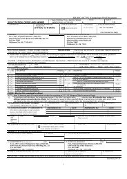
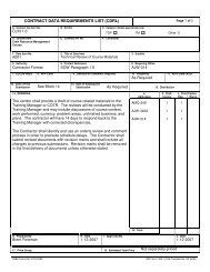
DEPARTMENT OF TRANSPORTATIONFEDERAL AVIATION ADMINISTRATIONTRANSMITTAL OF SHOP DRAWINGS, EQUIPMENT DATA, MATERIAL SAMPLESDATE SUBMITTEDOR MANUFACTURER’S CERTIFICATES OF COMPLIANCE FOR APPROVALREQUEST FOR APPROVAL OF THE FOLLOWING ITEMS CONTRACT NO.:TO: FROM: PROJECT TITLE AND LOCATIONSIGNATUREFTWIC-2235June, 2009.TRANSMITTAL NO.ITEM NO.DESCRIPTION OF ITEM SUBMITTED(TYPE, SIZE, MODEL NUMBER, ETC.)MFG. OR CATALOG, ORDRAWING NUMBER(S)VARIATION(See D1300)SPEC. PARAGRAPH(one section per transmittal)NO OFCOPIESRecommendedAction CodeFOR APPROVING AUTHORITY ONLYACTION CODES - APPROVED AS SUBMITTED - APPROVED AS NOTED - DISAPPROVEDApproval of samples, shop drawings and data is subject to corrections indicated and contract requirements.No responsibility is assumed for quantities or dimensions.APPROVED AS NOTED IN ACTION BLOCKPROJECT MANAGER/COTR DATE
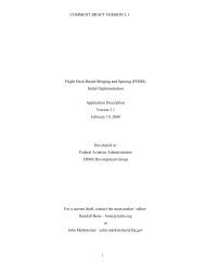
PROJECT NAME:REQUEST FOR INFORMATIONRFI NO.FTWIC-2235June, 2009.LOCATION:CONTRACT NO:STRUCTURALARCHITECTURALTO: REVIEWER: MECHANICALFROM: DATE SENT: ELECTRICALSPECIFICATION/DRAWING REF.:PLUMBINGREQUEST:SIGNATURE:DATE:RESPONSE:SIGNATURE:DATE:COPY: Project Manager: Field Rep: Designer:Architect/Engineer: Date Control Tech: <strong>Contract</strong> File:
THIS PAGE IS INTENTIONALLY BLANK
01400 QUALITY CONTROLFTWIC-2235June, 2009PART 1.00GENERAL1.01 WORK INCLUDED:A. FAA will secure the services of an independent, qualified testing laboratory for thepurpose of performing testing as required by the various sections of the <strong>specifications</strong>.Testing performed by the FAA will be paid for by the Government. <strong>Contract</strong>or shallcooperate fully with the <strong>Contract</strong>ing Officer and his testing laboratory to facilitate thetesting services.B. When re-testing is required due to noncompliance with the requirements of the<strong>specifications</strong>, <strong>Contract</strong>or shall pay for the re-testing.1.02 RELATED WORK SPECIFIED ELSEWHERE:Project <strong>Administration</strong> Section 01040Job Management Section 01041Testing of HVAC Systems Division 15Testing of Electrical Systems Division 161.03 DELIVERY AND STORAGE:Test cylinders made at the construction site shall be handled and protected in accordance withrecognized test procedures.1.04 JOB CONDITIONS:A. The <strong>Contract</strong>ing Officer reserves the right to perform testing at any state of construction.<strong>Contract</strong>or shall make the site available to the Government's testing organization, andshall cooperate fully in the performance of these tests. Where the <strong>Contract</strong>ing Officer hasmade it known that certain testing is to be performed, <strong>Contract</strong>or shall give FAAadequate notice before proceeding with work that would interfere with testing.B. <strong>Contract</strong>or is responsible to notify the <strong>Contract</strong>ing Officer at such times that testing isrequired. Do not proceed with any work until testing services have been performed and<strong>Contract</strong>ing Officer approves results of tests.C. The Government reserved the right to have 30 days after test samples have been madeprior to rendering a decision on such tests.D. The FAA reserves the right to direct re-testing in the event of failure and any re-testsshall be at the <strong>Contract</strong>or's expense.PART 2.00PRODUCTS [Not Used]01400-1
PART 3.00EXECUTIONFTWIC-2235June, 20093.01 TESTING:A. Perform all tests as indicated in the various sections of the <strong>specifications</strong>. Provide<strong>Contract</strong>ing Officer 24 to 48 hours notice of any testing.B. Cooperate with the Government and its testing laboratory. Provide complete access tothe site and make <strong>Contract</strong> Documents available. <strong>Contract</strong>or shall furnish samplematerial required for testing and shall furnish personnel and equipment needed to performsampling, or to assist in making the field tests. Deliver samples or test cylinders to thelocation designated by the <strong>Contract</strong>ing Officer.C. Samples made at the site and sent to a testing laboratory for performance of testing shallbe identified by the <strong>Contract</strong>or in such a manner that designates the exact location atwhich the sample was taken. Concrete cylinders shall be marked with a uniqueidentification number which corresponds to a log number. The log will include theconcrete company, truck or ticket number, mix design, time of day, temperature ofambient air and concrete temperature. The drawings will be marked with a colored markwhich identifies the extent of concrete placed as represented by the test cylinder.D. All other samples will be identified with such information suitable to identify the sourceand such other information required by the <strong>Contract</strong>ing Officer.E. Testing of HVAC and Electrical Systems are specified under the individual Sections ofDivision 15 and 16.END OF SECTION01400-2
THIS PAGE IS INTENTIONALLY BLANK
01700 CONTRACT CLOSEOUTFTWIC-2235June, 2009PART 1.00GENERAL1.01 WORK INCLUDED:The contractor shall turn over the entire closeout documents required and notify the FAA in writing asdetailed in the section that the work is complete.1.02 RELATED WORK COVERED ELSEWHERE:JOB MANAGEMENT Section 010411.03 QUALITY ASSURANCE:The contractor is soley responsible for compliance with the contract documents. Prior to requesting anyinspections, the contractor shall inspect the work of their own labor force and/or subcontractors. The FAAmay request copies of the contractors inspection before responding.PART 2.00DOCUMENTS2.01 COMPLETION CERTIFICATE:When the contractor considers the work is complete, the <strong>Contract</strong>or shall submit written certification thatthe contract documents have been reviewed; work has been inspected for compliance with contract;equipment and systems have been tested in the presence of the COR and are operational; requiredoperational, and maintenance manuals, data, and parts list have been submitted and approved; spare partshave been provided as required; required instruction of maintenance personnel has been accomplished;and work is completed, premises cleaned and ready for inspection.2.02 AS BUILT DRAWINGS:The contractor shall provide 3 complete sets of As-Built drawings along with the completion certificate.The final inspection will not be granted unless all three sets of As-Built drawings have been provided.2.03 FINAL INSPECTION:A written request for a final inspection must be sent to the COR 14 calendar days prior to the requestedinspection date. The <strong>Contract</strong>or shall develop his own pre-final inspection and correct all deficienciesprior to requesting the final inspection. The HVAC Commissioning process shall be completed prior tothe request for final inspection The <strong>Contract</strong>or shall furnish a copy of his final/completed punch list(pre-final report) and the completion certificate along with the request for final inspection. The finalinspection shall be scheduled at a mutually agreed date, and will be acknowledged by the COR. The prefinalreport must accompany the final inspection request.At the <strong>Contract</strong>or’s request a FAA preliminary punch list can generated only after the <strong>Contract</strong>or suppliesthe FAA with his punch list (pre-final report).If during the final inspection, the COR, in concurrence with the inspection team and <strong>Contract</strong>ing Officerdetermines that the General <strong>Contract</strong>or was not ready for the final inspection, based on the <strong>Contract</strong>or notmeeting all of the contractual requirements, all cost incurred by the Government for additional inspectionsshall be deducted from the contract (such as, but not limited to: travel cost, per diem, salaries of allconcerned parties, Consultant Engineer personnel required to participate in the final inspection). Thisdollar amount shall be actual cost incurred by the FAA to perform the inspection.01700-1
FTWIC-2235June, 20092.04 PUNCH LIST:During the final inspection, the COR (in coordination with the Regional Office and local FAA personnel)shall develop a list (Punch List) of all discrepancies (unsatisfactory work, latent or patent defects). Anunofficial list will be furnished to the contractor as a draft list upon completion of the final inspection.The official punch list will be generated by the FAA and will come from the <strong>Contract</strong>ing Officer.The <strong>Contract</strong>ing Officer will furnish, to the General <strong>Contract</strong>or, the official Punch List within fourteendays after the final inspection. The General <strong>Contract</strong>or shall be allowed 30 days to correct all deficienciesnoted. Completion of all Punch List items shall be completed within the contract period.2.05 ACCEPTANCE OF WORK:The contractor shall correct discrepancies noted during the final inspection, clean the premises and notifythe COR in writing that the work is ready for acceptance. The COR shall verify all items on the punchlist has been corrected and initialize/date each item that it is complete.2.06 WARRANTIES:A. POSTED WARRANTY INFORMATION:Provide all warranty certificates documenting the standard one-year warranty period. The warrantyperiod begins upon the date the work has been accepted. The warranty certificates shall bear the startand end dates of the warranty period, points of contacts complete company names, personnel names,addresses and telephone numbers. Each certificate shall be framed and sealed under glass andinstalled/mounted at locations as directed by the COR.B. EXTENDED EQUIPMENT/PRODUCT WARRANTIES:Equipment/Product Warranty List: Obtain and furnish to the <strong>Contract</strong>ing Officer a bound and indexednotebook containing written warranties for equipment/products that have extended warranties(warranty periods exceeding a one-year warranty period) furnished under the contract, and prepare acomplete listing of such equipment/products. The equipment/products list shall state the <strong>specifications</strong>ection applicable to the equipment/product, duration of the warranty therefor, start date of thewarranty, ending date of the warranty, and the point of contact for fulfillment of the warranty. Thewarranty period shall begin on the same date as project acceptance and shall continue for thefull/product warranty period. This listing shall be fully executed and delivered to the <strong>Contract</strong>ingOfficer prior to final acceptance of the facility, and acceptable listing shall be a condition of finalacceptance of the facility.01700-2
FTWIC-2235June, 2009C. EQUIPMENT WARRANTY TAGS AND GUARANTOR’S LOCAL REPRESENTATIVE:Furnish with each warranty the name, address, and telephone number of the guarantor's representativenearest to the location where the equipment and appliances are installed. The guarantor'srepresentative, upon request of the using service's representative, will honor the warranty during thewarranty period, and will provide the services prescribed by the terms of the warranty. At the time ofinstallation, tag each item of warranted equipment with a durable, oil- and water-resistant tagapproved by the <strong>Contract</strong>ing Officer. Attach tag with copper wire and spray with a clear siliconewaterproof coating. Leave the date of acceptance and inspector's signature blank until project isaccepted for beneficial occupancy. Tag shall show the following information:Type of Equipment/Product ____________________Warranty Period __________ From __________ To __________<strong>Contract</strong> No. ____________________Inspector's Signature ____________________ Date Accepted _______________Construction <strong>Contract</strong>or:Name: ____________________Address: _______________________Telephone: _______________________Warranty Contact: __________________Name: ____________________Address: ________________________Telephone: ________________________PART 3.00EXECUTION3.01 PRE-INSPECTION:The contractor shall perform an inspection of all the work prior to requesting a final inspection. Thecontractor shall provide a written list of deficiencies for each of their suppliers and subcontractors. Copiesof all lists shall be provided to the FAA COR.3.02 CLEAN-UP:After acceptance of work, the premises shall be cleaned a final time. Clean interior and exterior glasssurfaces; remove temporary labels, stains and foreign substances; polish transparent and glossy surfaces;vacuum carpeted and fabric surfaces. Clean equipment and fixtures to a sanitary condition. Replace filterson operating equipment. Clean debris from roofs, gutters, downspouts and drainage systems. Sweeppaved areas and rake clean landscaped areas. Remove waste and surplus materials, rubbish andconstruction facilities from the site.END OF SECTION01700-3
THIS PAGE LEFT BLANK INTENTIONALLY
01710 CLEANINGFTWIC-2235June, 2009PART 1.00GENERAL1.01 WORK INCLUDED:Just prior to occupancy of the building by the Government, and prior to <strong>Contract</strong> Acceptance Inspection(CAI), the <strong>Contract</strong>or shall perform a thorough cleaning of the site, buildings, and other structures.1.02 RELATED WORK COVERED ELSEWHERE:Project <strong>Administration</strong> Section 01040Job Management Section 01041Temporary Facilities Section 01510O&M Manuals Section 017301.03 SUBMITTALS:A. Submittals shall be in accordance with Section 01300 SUBMITTALS, and shall include thefollowing:1) Record of Finishes2) Maintenance InstructionsB. Include a typewritten description of finish materials along with a list of the cleaning productsrecommended by the manufacturer. Include these forms in the appropriate section of the O & MManual. Refer to Section 01730 Operational and Maintenance Manuals. Include the descriptionof maintenance needed, including daily, weekly, and monthly maintenance instructions.Complete a maintenance instruction form for the following:Vinyl Composition TileAcoustical TileCeramic TileVinyl Wall FabricCarpetPART 2.00PRODUCTS2.01 MATERIALS:Furnish all materials and equipment needed for cleaning and waxing purposes. Cleaners and waxes shallbe as recommended by the manufacturer for the individual material.01710-1
PART 3.00EXECUTIONFTWIC-2235June, 20093.01 SITE CLEANING:The <strong>Contract</strong>or shall maintain the site in a clean condition at all times. At the end of each work day<strong>Contract</strong>or shall gather all loose trash and debris from around the site and place in trash containers orremove from site. <strong>Contract</strong>or shall not stack trash or other construction debris on the ground or in theopen. Trash must be placed inside closed containers. In no event shall trash or debris be allowed tobecome airborne or be allowed to blow around or off site.3.02 ROUTINE CLEANING:A. Buildings shall be routinely cleaned to remove all construction debris, packing crates, wrappings,packing materials, or other trash. Each trade shall be responsible to remove trash and debrisresulting from his operations.B. Generally the entire space of buildings shall be maintained in a clean condition at all times. Oncepartitions have been installed, spaces shall be maintained in a "broom-clean" condition. Prior toinstallation of finishes and paint, spaces shall be thoroughly cleaned of trash and debris, floorsswept clean and mopped to remove dust.3.03 FINAL CLEANING:A. Thoroughly clean the entire building and make ready for occupancy. Remove constructiondebris, boxes and trash. Clean the entire site, removing all trash from the site. Removeconstruction storage sheds and field offices and restore grade to match surrounding condition.Remove excess dirt and complete sitework.B. Clean floor and inspect for damage. Replace damaged flooring. Remove paint dripping andother spillage. Sweep floors clean, then mop repeatedly until thoroughly clean. Resilientflooring shall be cleaned with an approved cleaner and given a one coat application of liquid floorpolish as recommended by the manufacturer. Polish to buffed appearance with powered floorbuffer. Remove oil, grease and other contaminants from concrete floors, then mop repeatedlyuntil thoroughly clean. Vacuum carpets with powered floor sweepers to remove dirt and dust.Remove glue or other substances from nap of carpet.C. Clean and polish inside and outside surfaces of all glass. After washing with window cleaner andwater, apply a coat of high quality glass polish and wipe clean. Clean and polish mirrors to aclear luster, free of smears or dried polish. Do not scratch or otherwise mar glass surfaces.D. Clean wall surfaces to remove dirt or scuff marks. Remove excess adhesive along top edges ofwall base. Remove adhesive from surfaces of vinyl wall coverings.E. Inspect acoustical tile. Align tile to fit properly in grid. Replace cracked or damaged tile.Remove smear marks and other dirt from tile. Clean surface or grid system.F. Inspect all painted surfaces. Spot paint nicks and other damage. If spot-painting does not blendinto the existing color and texture of the surrounding surfaces, repaint wall from inside corner toinside corner.01710-2
FTWIC-2235June, 2009G. Clean all plumbing fixtures, valves and trim. Clean toilet seats and covers. Remove labels andadhesive from fixtures. Remove floor drains and clean baskets or buckets. Polish strainers.Polish exposed chrome or brass.H. Clean mechanical rooms. Remove dirt and dust from equipment and apparatus with vacuum orcompressed air. Remove oil, grease and other contaminants from floors and equipment. Removeand clean screens at strainers in piping systems. Clean, insects and dust from louver screens.I. Clean and polish ceramic tile floors and wall surfaces. Remove mildew or other stains. Tuckpoint defective joints.J. Inspect all exterior painted surfaces. Spot paint any damaged surfaces. Damaged surfaces onfactory finished equipment shall be touched up with special paint furnished by the manufacturer.END OF SECTION01710-3
THIS PAGE IS INTENTIONALLY BLANK
01730 OPERATIONAL AND MAINTENANCE MANUALSFTWIC-2235June, 2009PART 1.00GENERAL1.01 WORK INCLUDED:Prepare three (3) copies of identical Maintenance Brochures bound in three-ring, loose leaf, hardcover binders. These brochures shall be indexed as to sections, and sub-divided by cardboardsheets having an identification tab in one corner. Provide division sheets to create the followingsub-divisions:(1) Table of Contents(2) Operating Instructions(3) Parts Lists and Descriptive Data(4) Warranties and Guarantees(5) Identification Legends(6) As-Built Drawings(7) Maintenance Instructions(8) Preventive Maintenance(9) Corrective Maintenance(10) Test Results(11) Colors & Patterns(12) Material Safety Data Sheets(13) Asbestos Certification Letters(14) <strong>Contract</strong>or Information1.02 WORK COVERED ELSEWHERE:Identification Systems Section 01080Submittals Section 01300Quality Control Section 014001.03 QUALITY ASSURANCE:<strong>Contract</strong>or shall review all submittals and include required information for future maintenanceand operational procedures.1.04 SUBMITTALS:Submit operation and maintenance (O&M) data/manuals which are specifically applicable to thiscontract and a complete and concise depiction of the provided equipment or product. Datacontaining extraneous information to be sorted through to find applicable instructions will not beaccepted. Present information in sufficient detail to clearly explain user O&M requirements atthe system, equipment, component, and subassembly level. Include an index preceding eachsubmittal. Submit in accordance with this section and Section 01300, "Submittals."01730-1
A. QUANTITY:FTWIC-2235June, 2009Submit three copies of the manufacturers' O&M information specified herein for thecomponents, assemblies, subassemblies, attachments, and accessories.B. PACKAGE CONTENT:For each product, system, or piece of equipment requiring submission of O&M data,submit the data package required in the individual technical section.C. DELIVERY:Submit O&M data to the <strong>Contract</strong>ing Officer for review and acceptance; submit dataspecified for a given item within 30 calendar days after the item is delivered to thecontract site.D. CHANGES TO SUBMITTALS:1.05 GUARANTEES:Manufacturer-originated changes or revisions to submitted data shall be furnished by the<strong>Contract</strong>or if a component of an item is so affected subsequent to acceptance of the O&Mdata. Changes, additions, or revisions required by the <strong>Contract</strong>ing Officer for finalacceptance of submitted data, shall be submitted by the <strong>Contract</strong>or within 30 calendardays of the notification of this change requirement.After approval, copies of manufacturer's warranties and written guarantees will be included in theO&M manual. <strong>Contract</strong>or shall include a written guarantee to cover the entire constructionagainst defect in materials or resulting from workmanship for a period of one (1) year from theGovernment's date of acceptance.1.06 JOB CONDITIONS:Drawings shall be folded to 8 1/2” x 11” or similar size, with all drawings having the same sizewhen folded. Drawings shall unfold easily without opening the binder retaining rings.1.07 MANUFACTURER'S WARRANTIES AND PARTS LISTS:<strong>Contract</strong>or shall acquire all packing lists, parts list and warranties that are packed along withequipment delivered to the site. Include along with other data in the O & M Manuals as requiredin Section 01730 OPERATIONAL AND MAINTENANCE MANUALS.PART 2.00PRODUCTS2.01 MATERIALS:A. Binders shall be large, three ring, hard back binders, all having the same color. Bindershall have a vinyl covering over all exterior surfaces. Prepare a label and insert in a clearpocket which will be readable when in a shelf. When the content of the manual exceeds athickness of 2 1/2 inches, the information will be placed in multiple binders, each notexceeding 2 1/2 inches, or in screw-post type binders.01730-2
FTWIC-2235June, 2009B. Index sheet shall be heavy weight cardboard having reinforced binding edge, and clearplastic tabs.PART 3.00EXECUTION3.01 MAINTENANCE MANUALS:Content of each section shall be as follows:A. OPERATING INSTRUCTIONS:Include typewritten, well-organized, step-by-step procedures for the normal operation ofeach major item of equipment. Instructions shall refer to equipment by identificationnumber corresponding to an identification device placed on the corresponding equipmentas shown on the drawings. Include specific instructions, procedures, and illustrations forthe following phases of operation:1. SAFETY PRECAUTIONS:List personnel hazards and equipment or product safety precautions for alloperating conditions.2. OPERATOR PRESTART:Include procedures required to set up and prepare each system for use.3. STARTUP, SHUTDOWN, AND POSTSHUTDOWN PROCEDURES:Provide narrative description for each operating procedure including controlsequence for each.4. NORMAL OPERATIONS:Provide narrative description of normal operating procedures. Include controldiagrams with data to explain operation and control of systems and specificequipment.5. EMERGENCY OPERATIONS:Include emergency procedures for equipment malfunctions to permit a shortperiod of continued operation or to shut down the equipment to prevent furtherdamage to systems and equipment. Include emergency shutdown instructions forfire, explosion, spills, or other foreseeable contingencies. Provide guidance onemergency operations of all utility systems including valve locations andportions of systems controlled.6. OPERATOR SERVICE REQUIREMENTS:Include instructions for services to be performed by the operator such aslubrication, adjustment, inspection, and gage reading recording.01730-3
7. ENVIRONMENTAL CONDITIONS:FTWIC-2235June, 2009Include a list of environmental conditions (temperature, humidity, and otherrelevant data) which are best suited for each product or piece of equipment anddescribe conditions under which equipment should not be allowed to run.B. PARTS LIST AND DESCRIPTIVE DATA:1. Furnish wiring diagrams, packing lists, installation instructions, and other printedinformation furnished by the manufacturer. Major items shall have a printedparts list included. Include any information specified in the various sections ofthe <strong>specifications</strong>.2. Include one complete set of approved Submittals for the following items:Light FixturesHVAC EquipmentWater HeatersSwitchgear & Panel boardsPumpsPlumbing FixturesHardware3. Furnish manufacturer's printed parts list or descriptive data for the followingitems:HVAC EquipmentAppliancesElevatorExhaust FansAir Handling EquipmentC. WARRANTIES AND GUARANTEES:Furnish manufacturer's printed warranties and <strong>Contract</strong>or's typewritten guarantee, alongwith other guarantees specified in the various sections of the <strong>specifications</strong>. List andexplain the various warranties and include the servicing and technical precautionsprescribed by the manufacturers or contract documents to keep warranties in force.Include warranty information for primary components such as the compressor of airconditioning system.D. IDENTIFICATION LEGENDS:1. Furnish a typewritten legend to correspond with identification devices installedon piping and equipment. Refer to Section 01080 IDENTIFICATIONSYSTEMS. Legend is to list the identifying device, its location, a briefdescription of the devices function, and the I.D. number.2. Include a typewritten electrical panel board legend for each panel board andswitchboard installed in the project. This information shall be a duplicate of thelegend placed in the panel board.01730-4
E. AS-BUILT DRAWINGS:FTWIC-2235June, 20091. On a sepia print, mark exact location of underground utilities, measured from apermanent reference point. Also note depth of utility at the building as well as atthe connection to the main.2. Note exact location of hidden valves or control equipment. Note any changes inequipment locations that occurred during construction.F. MAINTENANCE INSTRUCTIONS:Complete a typewritten "Maintenance Instruction Form" which describes the cleaningprocedures necessary for each type of finished surface. Description to list suggestedcleaning products, waxes, or other products on the following materials:Resilient TileAcoustical TilePaintVinyl Wall FabricCeramic or Quarry TileCarpetG. PREVENTIVE MAINTENANCE:Include the following information for preventive and scheduled maintenance to minimizecorrective maintenance and repair.1. LUBRICATION DATA:Include lubrication data as follows:a) A table showing recommended lubricants for specific temperature rangesand applications.b) Charts with a schematic diagram of the equipment showing lubricationpoints, recommended types and grades of lubricants, and capacities.c) A lubrication schedule showing service interval frequency.2. PREVENTIVE MAINTENANCE PLAN AND SCHEDULE:Include manufacturer's schedule for routine preventive maintenance, inspections,tests and adjustments required to ensure proper and economical operation and tominimize corrective maintenance and repair. Provide manufacturer's projectionof preventive maintenance work-hours on a daily, weekly, monthly, and annualbasis including craft requirements by type of craft. For periodic calibrations,provide manufacturer's specified frequency and procedures for each separateoperation.H. CORRECTIVE MAINTENANCE:Include manufacturer's recommendations on procedures and instructions for correctingproblems and making repairs.1. TROUBLESHOOTING GUIDES AND DIAGNOSTIC TECHNIQUES:01730-5
FTWIC-2235June, 2009Include step-by-step procedures to promptly isolate the cause of typicalmalfunctions. Describe clearly why the checkout is performed and whatconditions are to be sought. Identify tests or inspections and test equipmentrequired to determine whether parts and equipment may be reused or requirereplacement.2. WIRING DIAGRAMS AND CONTROL DIAGRAMS:Wiring diagrams and control diagrams shall be point-to-point drawings of wiringand control circuits including factory-field interfaces. Provide a complete andaccurate depiction of the actual job specific wiring and control work. Ondiagrams, number electrical and electronic wiring and pneumatic control tubingand the terminals for each type, identically to actual installation numbering.3. MAINTENANCE AND REPAIR PROCEDURES:Include instructions and list tools required to restore product or equipment toproper condition or operating standards.4. REMOVAL AND REPLACEMENT INSTRUCTIONS:Include step-by-step procedures and list required tools and supplies for removal,replacement, disassembly, and assembly of components, assemblies,subassemblies, accessories, and attachments. Provide tolerances, dimensions,settings and adjustments required. Instructions shall include a combination oftext and illustrations.5. SPARE PARTS AND SUPPLY LISTS:Include lists of spare parts and supplies required for maintenance and repair toensure continued service or operation without unreasonable delays. Specialconsideration is required for facilities at remote locations. List spare parts andsupplies that have a long lead time to obtain.6. CORRECTIVE MAINTENANCE WORK-HOURS:I. TEST RESULTS:Include manufacturer's projection of corrective maintenance work-hoursincluding craft requirements by type of craft. Corrective maintenance thatrequires participation of the equipment manufacturer shall be identified andtabulated separately.Install copies of test results for each test required in these <strong>specifications</strong>. Include a copyof City Inspection Final Approval or Certification. Include information on testequipment required to perform specified tests and on special tools needed for theoperation, maintenance, and repair of components.01730-6
J. COLOR AND PATTERNS:FTWIC-2235June, 2009Provide a typewritten record of finished materials having colors or patterns. Identify thematerial, the location the material is installed, the manufacturer, material type, pattern,and color. Paints shall be identified by manufacturer and color code. Paint colors whichrequire special tinting shall be identified with the formula needed to reproduce the color.K. MATERIAL SAFETY DATA SHEETS (MSDS):<strong>Contract</strong>or shall include a copy of the MSDS in the O&M Manuals.L. ASBESTOS CERTIFICATION LETTERS:<strong>Contract</strong>or shall include a copy of the asbestos certification letters in the O&M Manuals.M. CONTRACTOR INFORMATION:Provide a list that includes the name, address, and telephone number of the General<strong>Contract</strong>or and each subcontractor installing the product or equipment. Include localrepresentatives and service organizations most convenient to the project site. Provide thename, address, and telephone number of the product or equipment manufacturers.END OF SECTION01730-7
THIS PAGE IS INTENTIONALLY BLANK
02100 SITE PREPARATIONFTWIC-2235June, 2009PART 1.00GENERAL1.01 WORK INCLUDED:Furnish labor, materials, equipment and incidentals necessary to prepare the site for construction,including the removal of trees and brush, and disposal of construction debris.1.02 RELATED WORK COVERED ELSEWHERE:Temporary Facilities Section 015101.03 JOB CONDITIONS:A. Except where further excavation extends beyond the cavities resulting from workperformed under this section, fill holes with appropriate backfill material and compact tothe density of the surrounding undisturbed soil. Finish the site by blading or othermethods to smooth the area, remove ditches, mounds, or other natural or manmadeirregular features. Blend grades together in a smooth uniform manner.B. Felled trees, brush, lumber, concrete, and other debris shall become the property of the<strong>Contract</strong>or, and shall be promptly removed from the site.PART 2.00PART 3.00PRODUCTS [Not Used]EXECUTION3.01 PREPARATION:A. Mark areas to be cleared and grubbed prior to commencing clearing operations.<strong>Contract</strong>ing Officer shall approve clearing and grubbing limits prior to commencement ofclearing operations.B. Remove brush outside the clearing limits, but within the immediate vicinity of the work,upon receipt of approval from the <strong>Contract</strong>ing Officer, when brush interferes with orretards the progress of construction operations.C. The clearing limits shall not extend beyond the project limits.3.02 INSTALLATION:A. Scrape the entire parking pavement as shown on contract drawings, including structures,or other pavements clear of brush.B. Remove any concrete or masonry structures within the limits of the construction, or asotherwise indicated, including concrete slabs, foundations, pavements, or othercomponents. The existing curb and gutter shall remain.C. Remove underground structures such as abandoned manholes, vaults, and distributionfield piping, inlets, buried trash, or debris.02100-1
FTWIC-2235June, 2009D. Take precautions during excavation procedures to guard against damage to activeunderground piping. In the event that inactive or abandoned pipelines are uncovered,determine that the lines are inactive, then remove buried piping within the limits ofconstruction, or 4'-0" beyond the limits of buildings or other structures, or as needed toclear excavations. Plug both ends of such abandoned piping with concrete plugs.3.03 FIELD QUALITY CONTROL:Check the local regulations and consult with the Owner to determine whether burning will bepermitted on the site.END OF SECTION02100-2
03300 CAST-IN-PLACE CONCRETEFTWIC-2235June, 2009PART 1.00GENERAL1.01 WORK INCLUDED:Furnish labor, materials, mixing and transporting equipment and incidentals necessary toproportion, mix, transport, place, consolidate, finish and cure normal weight concrete in thestructure.1.02 RELATED WORK COVERED ELSEWHERE:Concrete Testing Laboratories Section 01400Reinforcing Section 03200Precast Concrete Section 03411Structural Steel Section 05120Structural Embeds and Anchor Plates Section 055001.03 QUALITY ASSURANCE:A. DESIGN CRITERIA:1. Concrete shall be composed of Portland Cement, fine aggregate, coarseaggregate, admixtures and water, as specified.2. ACI 211.1 shall be the basis for selecting the proportions for concrete made withaggregates of normal density and of workability suitable for usual cast-in-placestructures.3. The design of the concrete shall be consistent with the minimum requirements ofstrength and proportions stated herein and in accordance with ACI Standard211.1 "Recommended Practice for Selecting Proportions of Concrete," subject tomaximum water cement ratio, minimum cement content and minimum strengthsspecified.4. The workability of any mix shall be as required for the specific placingconditions and the method of placement. The concrete shall have the ability tobe worked readily into corners and around reinforcing steel without thesegregation of materials or the collection of free water on the surface.Compliance with specified slump limitations shall not necessarily designate asatisfactory mix.5. In no case shall the amount of coarse material produce harshness in placing orhoneycombing in the structure, when forms are removed.B. CONCRETE CLASSIFICATIONS:(see following page for chart)03300-1
FTWIC-2235June, 2009Min.28 Day Min.Comp. Sacks of Max. Size Max. WaterStrength Cement Aggregate Gals/Bag Max. SlumpClass (psi) Per/C.Y. (in.) (net) (in.)*A 4000 6.0 1.5 5.25 4-6Size No.467B 4000 6.0 1.5 5.25 4Size No.467C 4000 6.0 1.0 5.25 4Size No.57D 6000 6.5 0.75 5.25 5Size No.67E 2000 4.0 1.5 7.0 4Size No.467F 1000 3.0 1.5- 1-1/2 - 3Size No.467G 4000 6.5 0.375 5.25 4Size No.8* Maximum slump with water high range reducing admixture may be increased to 7" - 9".C. CONCRETE USAGE:Class A Use: All reinforced concrete on ATCT/Base-EG Building unless otherwisespecified; All Slabs on Metal Floor Decks, Sidewalks, Manholes, Storm Drains,PavementClass B Use: All reinforced concrete on Tower unless otherwise specifiedClass C Use: Pumped Concrete, Concrete Piers, Thin Wall SectionsClass D Use: Precast ConcreteClass E Use: Cradling, Blocking, Foundation SealClass F Use: Lean Concrete BackfillClass G Use: Stair Pans and Landings1. The maximum amount of coarse aggregate (dry loose volume) per cubic foot offinished concrete shall not exceed 0.82 cubic feet.2. The maximum amount of water, as established in the table above, includes thewater in the aggregate, with the aggregates in a saturated, surface-dry condition.3. The maximum water content shall be the amount added at the mixer, plus the freewater in the aggregate, and minus the absorption of the aggregate based on a30-minute absorption period. No allowance shall be made for the evaporation ofwater after batching. If additional water is required to obtain the desired slump, acompensating amount of cement shall also be added. The maximum03300-2
FTWIC-2235June, 2009water-cement ratio shall not be exceeded. No additional compensation shall bemade for additional cement.4. If fly ash is to be used in place of cement, no more than 20 percent of the cementmay be replaced. The amount of fly ash used in place of the cement shall be 20percent greater than the amount of cement removed.D. CONCRETE STRENGTH:The concrete mix shall be designed with the intention of producing concrete which hascompressive or flexural strength equal to or greater than the following, when tested inaccordance with ASTM C-39 and ASTM C-293.E. TRIAL MIXES:MinimumCompressive Strength(lbs. per sq. in.)7 Day 28 DayMinimumFlexural Strength(lbs. per sq. in.)4 Day 7 DayClass ofConcreteA 3,000 4,000 450 550B 3,000 4,000 450 550C 3,000 4,000 450 550D 4,000 6,000 480 600E 1,320 2,000 - -F - 1,000 - -G 3,000 4,000 450 5501. Laboratory samples shall be taken in accordance with the trial mix designs forlaboratory testing purposes.2. The fresh concrete shall be tested for Slump (ASTM C-143) and Air Content(ASTM C-173 and ASTM C-231). Strength test specimens shall be made, curedand tested for seven (7) and twenty-eight (28) day strength in accordance withASTM C-192, ASTM C-39, and ASTM C-293.3. Suitable facilities shall be provided for readily obtaining representative samplesof aggregate from each of the weigh batchers for test purposes and for obtainingrepresentative samples of concrete for uniformity tests. The necessary platforms,tools, and equipment for obtaining samples shall be furnished. Aggregates shallbe tested in accordance with ASTM C-289.4. The proportions of materials entering into the trial mix shall be laboratory testedprior to concrete placing. The cement contents specified are minimum values. Ifadditional quantities are required to obtain the specified strengths, supply thecement at no additional cost to the Government.5. A trial mix shall be designed by an independent testing laboratory, retained andpaid by the <strong>Contract</strong>or and approved by the Owner. The testing laboratory shallsubmit verification that the materials and proportions of the trial concrete mixdesign meet the <strong>specifications</strong>. The laboratory trial concrete mix design shall besubmitted to the <strong>Contract</strong>ing Officer before the 7-day strength tests are made.03300-3
FTWIC-2235June, 20096. Laboratory tests on trial mixes shall show a 28-day strength higher than thestated minimum 28-day strength per ACI 318, Table 5.3.2.2. From thesepreliminary tests, the ratios between 7-day and 28-day strengths shall beestablished to determine at seven (7) days the strengths necessary to satisfy therequired 28-day strengths. The 7-day trial mix strength test results shall besubmitted to the <strong>Contract</strong>ing Officer at least 14 days in advance of the 28-daystrength tests. The final results of the 28-day compressive strength tests shall besubmitted to the <strong>Contract</strong>ing Officer at least ten (10) days prior to the scheduledbeginning of concrete placement approved by the <strong>Contract</strong>ing Officer prior to theplacement of any concrete.7. Two mix designs shall be designed for each class of concrete that contains a highrange water reducer. Both mix designs shall be designed for this project usingmaterials that are to be used in the concrete. Mix designs from previous projectsshall not be acceptable. Concrete mix designs which are to have high rangewater reducing admixtures shall have the trial mix designed without theadmixture. Laboratory test results shall show that the mix design meets all otherrequirements of the specification without the admixture. After the initial trialmix design is tested, another mix design shall be proposed using the sameportions in the initial mix design with the addition of the admixture. Testing ofthe concrete shall be performed under the guidance of the admixturemanufacturer's representative to determine dosage, addition times, andcompatibility with other admixtures and mixture constituents. In addition to thetest performed in the first trial mix, the second mix, with admixture added, shallhave tests performed and results tabulated that show slump retention for a 90minute time period, temperature control for 90 minutes, as well as compressivestrengths, and entrained air.F. TESTING:1. GENERAL:a) Tests shall be required throughout the work to monitor the quality ofconcrete. Samples shall be taken in accordance with ASTM C-172.b) The <strong>Contract</strong>ing Officer may waive these requirements on concreteplacements of ten (10) cubic yards or less. However, evidence shall befurnished showing a design mix which meets the <strong>specifications</strong>.c) Testing of the materials, ready mix, transit mix or central plant concretewill be as specified in Section 01400 QUALITY CONTROL. Providehousing for the curing and storage of test specimens and equipment. Noconcrete shall be placed without a <strong>Contract</strong>ing Officer at either the plantor at the project site.03300-4
2. SLUMP TEST:FTWIC-2235June, 2009Slump tests, in accordance with ASTM C-143, shall be used to indicate theworkability and consistency of the concrete mix from batch to batch. Generally,a slump test shall be made at the start of operations each day, at regular intervalsthroughout a working day, and at any time when the appearance of the concretesuggests a change in uniformity.3. AIR CONTENT TEST:Tests for the concrete's air content shall be made in accordance with ASTM C-231 or ASTM C-173, at the point of delivery of concrete, prior to placing informs. The test shall be made frequently to monitor a proper air content uniformfrom batch to batch.4. COMPRESSION TEST:a) Compression test specimens shall be 6" x 12" concrete cylinders madeand cured in accordance with ASTM C-31. No fewer than two (2)specimens shall be made for each test at each age (7 and 28 days).Samples shall be taken at a minimum of every 150 cubic yards ofconcrete of each class placed. At least one (1) set of test specimens perday shall be made of each class of concrete used that day. Specimensshall be cured under laboratory conditions specified in ASTM C-31.Additional concrete cylinders may be required for curing on the jobunder actual job curing conditions. These samples could be requiredwhen:1) There is a possibility of the air temperature surrounding theconcrete falling below 40 degrees F, or rising above 90 degreesF.2) The curing procedure may need to be improved and/orlengthened.3) It is necessary to determine when the structure may be put intoservice.b) Compression strength tests shall be made on the laboratory-cured andjob-cured concrete cylinders at seven (7) and twenty-eight (28) days, inaccordance with ASTM C-39. The value of each test result shall be theaverage compressive strength of two (2) samples taken at the same timefrom the same batch of concrete. The tests made at seven (7) days shallshow strengths of not less than 2/3 of the design strength. For the 28-daycylinders, the strength level shall be satisfactory if the averages of all setsof three (3) consecutive strength test results exceed the required designcompressive strength, and no individual strength test result falls belowthe required compressive strength by more than 500 psi.03300-5
5. FAILURE TO MEET REQUIREMENTS:FTWIC-2235June, 20091.04 SUBMITTALS:a) Should the 7-day strengths shown by the test specimens fall below therequired values, additional curing shall be performed on those portions ofthe structures represented by the test specimens at the <strong>Contract</strong>or'sexpense. Test cores shall be obtained and tested in accordance withASTM Method of Obtaining and Testing Specimens from Drilled Coresand Sawed Beams of Concrete, Designation C-42. If additional curingdoes not give the strength required, the Owner reserves the right torequire strengthening, replacement of those substandard portions of thestructure, or additional testing, at the <strong>Contract</strong>or's expense.b) Upon receipt of the <strong>Contract</strong>or's written request, substandard concretework may be re-examined in place by non-destructive testing methods orcore samples, in accordance with ACI 301. The services of anindependent testing laboratory shall be retained and all expenses paid bythe <strong>Contract</strong>or. Laboratory results shall be evaluated by the <strong>Contract</strong>ingOfficer, who shall make the final decision on acceptability of theconcrete in question. Core sample holes shall be repaired to thesatisfaction of the <strong>Contract</strong>ing Officer.Submittals shall be in accordance with Section 01300, SUBMITTALS and shall include:A. Trial mix design, materials in the design, and independent laboratory test results for eachclass of concrete.B. Seven (7) day and twenty-eight (28) day compressive strength test results.C. Manufacturer's literature on materials. Submit certifications on bagged materials.D. Schedule of concrete placements.E. Drawing showing location of proposed construction joints.1.05 REFERENCES AND STANDARDS:Mixing, sampling, placing, curing and testing of concrete, and the materials used shall be incompliance with the latest revisions of the following standards, unless otherwise noted in the<strong>Contract</strong> Documents.A. AMERICAN SOCIETY FOR TESTING AND MATERIALS (ASTM)PUBLICATIONS:ASTM C-31ASTM C-33Test Methods of Making and Curing Concrete Test Specimens in theFieldSpecifications for Concrete Aggregates03300-6
ASTM C-39ASTM C-42ASTM C-87ASTM C-94FTWIC-2235June, 2009Test Methods for Compressive Strength of Cylindrical ConcreteSpecimensMethods of Obtaining and Testing Drilled Cores and Sawed Beams ofConcreteTest Method for Effect of Organic Impurities in Fine Aggregate onStrength of MortarSpecification for Ready-Mixed ConcreteASTM C-109 Test Method for Compressive Strengths of Hydraulic Cement Mortar(using 2-inch or 50 mm cube specimens)ASTM C-125ASTM C-143ASTM C-150ASTM C-156ASTM C-171ASTM C-172Terminology Relating to Concrete and Concrete AggregatesTest Method for Slump of Hydraulic Cement ConcreteSpecification for Portland CementTest Method for Water Retention by Concrete Curing MaterialsSpecification for Sheet Materials for Curing ConcretePractice for Sampling Freshly Mixed ConcreteASTM C-173 Test Method for Air Content of Freshly Mixed Concrete by theVolumetric MethodASTM C-191Test Method for Time of Setting of Hydraulic Cement by Vicat NeedleASTM C-192 Test Method of Making and Curing Concrete Test Specimens in theLaboratoryASTM C-231 Test Method for Air Content of Freshly Mixed Concrete by the PressureMethodASTM C-260ASTM C-289ASTM C-293Specification for Air Entraining Admixtures for ConcreteTest Method for Potential Reactivity of Aggregates (Chemical Method)Test Method for Flexural Strength of Concrete (Using Simple Beam withCenter-Point Loading)ASTM C-309 Specification for Liquid Membrane-Forming Compounds for CuringConcreteASTM C-494Specifications for Chemical Admixtures for ConcreteASTM C-579 Test Method for Compressive Strength of Chemical-Resistant Mortarsand Monolithic Surfacings03300-7
FTWIC-2235June, 2009ASTM C-580 Test Method for Flexural Strength and Modulus of Elasticity ofChemical-Resistant Mortars, Grouts, and Monolithic SurfacingsASTM C-618 Specification for Fly Ash and Raw or Calcined Natural Pozzolan for Useas Mineral Admixture in Portland Cement ConcreteASTM C-806ASTM C-827ASTM C-881Test Method for Restrained Expansion of Expansive Cement MortarTest Methods for Early Volume Change of Cementitious MixturesSpecification for Epoxy-Resin-Base Bonding Systems for ConcreteASTM D-570 Test Method for Water Absorption of PlasticsASTM D-638 Test Method for Tensile Properties of PlasticsASTM D-746 Test Method for Brittleness Temperature of Plastics and Elastomers byImpactASTM D-994 Specification for Preformed Expansion Joint Filler for Concrete(Bituminous Type)ASTM D-1190 Specification for Concrete Joint Sealer, Hot-Poured Elastic TypeASTM D-1752 Specification for Preformed Sponge Rubber and Cork Expansion JointFillers for Concrete Paving and Structural ConstructionASTM D-2240 Test Method for Rubber Property-Durometer HardnessASTM E-96Test Methods for Water Vapor Transmission of MaterialsB. FEDERAL SPECIFICATIONS (FED SPEC):TT-S-00227E Type II, Class A or B, Expansion Joint SealantCRD-C621-83 Corps of Engineers Specification for Non-Shrink GroutC. AMERICAN CONCRETE INSTITUTE (ACI) PUBLICATION:ACI 211.1ACI 214ACI 301ACI 304ACI 304.2RStandard Practice for Selecting Proportions for Normal, Heavy-weight,and Mass ConcreteRecommended Practice for Evaluation of Strength Test ResultsSpecification for Structural Concrete for BuildingsGuide for Measuring, Mixing, Transporting and Placing ConcretePlacing Concrete by Pumping Methods03300-8
ACI 305RACI 306RACI 308ACI 309ACI 318Hot Weather ConcretingCold Weather ConcretingStandard Practice for Curing ConcreteGuide for Consolidation of ConcreteBuilding Code Requirements for Reinforced ConcreteFTWIC-2235June, 20091.06 DELIVERY, HANDLING AND STORAGE:A. Deliver cement in bulk or bags which are plainly marked with the brand andmanufacturer's name. Immediately upon receipt, store cement in a dry, weather-tight andproperly ventilated structure, which excludes moisture. Storage facilities shall permiteasy access for inspection and identification. Cement not stored in accordance with therequirements shall not be used.B. Sufficient cement shall be in storage to complete placement of concrete started. In orderthat cement may not become unduly aged after delivery, maintain records of deliverydates. Use cement which has been stored at the site for 60 days or more before usingcement of lesser age. No cement shall be used which is lumped, caked, stored more than90 days, or whose temperature exceeds 170 degrees F.C. Handle and store concrete aggregate in a manner which prevents the admixture of foreignmaterials. If the aggregates are stored on the ground, grubb the sites for the stockpiles,clear weeds and grass and level. Do not disturb the bottom layer of aggregate or usewithout recleaning.D. Store different types and gradations of aggregates in a manner which preventsintermixing. Handle materials in stockpiles in a manner which prevents segregation ofmaterials in the pier. Build in layers not over 3' in depth. Should segregation occur,remix the aggregates to conform with the grading requirements. Stockpile fineaggregates at least twenty-four (24) hours before mixing to reduce the free moisturecontent.1.07 JOB CONDITIONS:A. GENERAL:1. The concrete shall be mixed in quantities required for immediate use. Anyconcrete which is not in place within the time limits specified shall not be used.Concrete shall not be re-tempered.2. Concrete shall not be placed if impending weather conditions would impair thequality of the finished work.B. CONCRETE TEMPERATURE:No concrete shall be placed when the temperature of the concrete to be placed is greaterthan 90 degrees F or less than 50 degrees F. The temperature of the concrete to be03300-9
FTWIC-2235June, 2009placed shall be taken by the <strong>Contract</strong>ing Officer with a thermometer immediately beforeplacement, with the point of measurement being in the chute or bucket.C. COLD WEATHER:1. If air temperature is at or below 40 degrees F, cold weather concreting shall beperformed in accordance with ACI-306R.2. No concrete shall be mixed or placed when the atmospheric temperature is at orbelow 35 degrees F. The temperature shall be taken in the shade away fromartificial heat.3. In cases where the temperature drops below 40 degrees F after the concretingoperations have been started, the sufficient canvas and framework or other typeof housing shall be furnished to enclose and protect the structure, in accordancewith the requirements of ACI-306R. Sufficient heating apparatus such as stoves,salamanders, or steam equipment and fuel to provide heat shall be supplied. Theconcrete shall be protected when placed under all weather conditions. Shouldconcrete placed under such conditions prove unsatisfactory, remove and replacethe concrete at no cost to the Government.4. When mixing with the air temperature below 40 degrees F, water used for mixingshall be heated to raise the concrete temperature to 70 degrees F. Thetemperature of the mixing water shall not exceed 165 degrees F when enteringthe mixer.5. If heating the mixing water only does not raise the placing temperature of theconcrete to 70 degrees F, the aggregate must also be heated, either by steam ordry heat, to raise the placing temperature of the concrete to the requiredtemperature. In no case shall the aggregate temperature exceed 150 degrees F asit enters the mixer. The heating apparatus shall heat the mass of the aggregateuniformly and preclude the occurrence of hot spots which burn the material.6. Salts, chemicals, or other foreign materials shall not be mixed with the concreteto preventing freezing. Calcium chloride is not permitted.D. HOT WEATHER:1. Hot weather is defined as any combination of high air temperature, low relativehumidity and wind velocity that impairs the quality of the concrete. Hot weatherconcreting shall be in accordance with ACI-305R. Concrete shall be placed inthe forms without the addition of any more water than that required by the design(slump). No excess water shall be added on the concrete surface for finishing.Control of initial set of the concrete and extending the time for finishingoperations may be accomplished with the use of approved water-reducing andset-retarding admixture, as specified.Maximum time intervals between the addition of mixing water and/or cement tothe batch, and the placing of concrete in the forms shall not exceed the following(excluding HRWR admixture use):03300-10
Concrete TemperatureFTWIC-2235June, 2009Maximum Time From Additionof Water to PlacementNon-Agitated ConcreteUp to 80 degrees FOver 80 degrees F30 Minutes15 MinutesAgitated ConcreteUp to 75 degrees F90 Minutes75 degrees to 89 degrees F 60 MinutesOver 90 degrees F(max. permissible concrete temp) 45 MinutesThe use of an approved set-retarding admixture will permit the extension of theabove time maximums by 30 minutes, for agitated concrete only.The use of an approved high range water reducing (HRWR) admixture will allowplacement time extensions as determined by the manufacturer.2. The maximum temperature of concrete shall not exceed 90 degrees F at the timethe concrete is placed. The temperatures of the mixing water shall be reduced bythe use of chilled water or ice.3. The maximum temperature of concrete with high range water reducing admixtureshall not exceed 100 degrees F at the time concrete is placed.4. Under extreme heat, wind, or humidity conditions, concreting operations may besuspended if the quality of the concrete being placed is not acceptable.PART 2.00PRODUCTS2.01 MATERIALS:A. CEMENT; GENERAL:If the fine and/or coarse aggregates test "Potentially Reactive", in accordance with ASTMC-289, a low alkali Portland Cement shall be used. The total alkali content calculated asthe percentage of sodium oxide (Na 2 O) plus 0.658 times the percentage of potassiumoxide (K 2 O) shall not exceed 0.6.03300-11
B. CEMENT; TYPE:FTWIC-2235June, 20091. Type "I" Portland Cement, general purpose, conforming to ASTM C-150; usedfor all concrete.2. Type "III" Portland Cement, high early strength conforming to ASTM C-150;may be used only with written approval of the COR.C. FLY ASH/POZZOLANS:Conforming to ASTM C-618, Class "F" fly ash; used in all classes of concrete. Asupplier's certificate of the analysis and composition of the fly ash shall be supplied.D. ADMIXTURES:Concrete of 3000 psi or stronger shall contain air-entraining admixtures. When jobconditions dictate, water-reducing and set-controlling admixtures may be used. Onlyspecified admixtures shall be used. Admixtures shall be batched at the batch plant.1. Air-Entraining Admixture: Conforming to ASTM C-260. The total average aircontent shall be in accordance with recommendations of ACI 211.1; 5% +/- 0.5%for 1-1/2" maximum size aggregate.2. Water Reducing Admixtures: Conforming to ASTM C-494; Types "A" or "D"only; accurately measured and added to the mix according to the manufacturer'srecommendations.3. Set Retarding Admixtures: Conforming to ASTM C-494; Types "B" and "D"only; accurately measured and added to the mix in according to themanufacturer's recommendations.4. Water Reducing Admixtures - High Range (HRWR): High Range WaterReducer shall comply with ASTM C-494, Type "F" or "G". HRWR shall beaccurately measured in accordance with the manufacturer's recommendations.HRWR shall be added to the concrete mix at the concrete batch plant. HRWRmay not be added at placement site except to redose a batch and only afterapproval of the HRWR manufacturer. The high range water reducing admixtureshall be able to maintain the plasticity range for extended periods of time (2hours if necessary) without a rise in concrete temperature. Type "F" or "G"admixtures may be used in all concrete except in Class E concrete. With the useof these admixtures, slump limit shall be between 7" and 9" unless otherwiseauthorized by the manufacturer. Other admixtures may only be used with theHRWR if approved by the HRWR manufacturer. A representative of the HRWRmanufacturer shall be present during any large placement, placement of slabs, orduring times of unusual circumstance which may require changes to the productformulation. High range water reducing agent shall be by Grace ConstructionProducts, "Daracem 100", or approved equal.03300-12
E. WATER:FTWIC-2235June, 20091. Clean and free from injurious amounts of oil, acid, alkali, salt, organic matter, orother deleterious substances. Water suitable for drinking or for ordinaryhousehold use shall be accepted for use without testing.2. Water for concrete from shallow, muddy, or marshy sources shall not be used.3. When comparative tests are made with water of known, satisfactory quality, inaccordance with ASTM C-87, any indication of unsoundness, marked change inthe time of set, or reduction of more than five (5%) percent in mortar strengthshall be cause for rejection.F. FINE AGGREGATE:1. Washed and screened natural sands or sands conforming to ASTM C-33. Thegradation in ASTM C-33 for air entrained concrete is:SIEVE SIZE PERCENT RETAINED PERCENT PASSING3/8" 0 100#4 0 - 5 95 - 100#8 0 - 20 80 - 100#16 15 - 50 50 - 85#30 40 - 75 25 - 60#50 70 - 90 10 - 30#100 90 - 98 2 - 102. Fine aggregate shall have not more than 45% percent retained between any two(2) consecutive sieves. Its fineness modulus, as defined in ASTM C-125, shallbe not less than 2.3 nor more than 3.1.G. COARSE AGGREGATE:1. Crushed stone or gravel conforming to ASTM C-33, in the gradation sizespecified.2. For gradation size number 467, a maximum aggregate size of 1-1/2" is:SIEVE SIZE PERCENT PERCENTSQUARE OPENING RETAINED PASSING2" 0 1001-1/2" 0 - 5 95 - 1003/4" 30 - 65 35 - 703/8" 70 - 90 10 - 30No. 4 95 - 100 0 - 503300-13
3. For gradation size number 57, the maximum aggregate size of 1" is:FTWIC-2235June, 2009SIEVE SIZE PERCENT PERCENTSQUARE OPENING RETAINED PASSING1-1/2" 0 1001" 0 - 5 95 - 1001/2" 40 - 75 25 - 60No. 4 90 - 100 0 - 10No. 8 95 - 100 0 - 54. For gradation size number 67, the maximum aggregate size of 3/4" is:SIEVE SIZE PERCENT PERCENTSQUARE OPENING RETAINED PASSING1" 0 1003/4" 0 - 10 90 - 1003/8" 45 - 80 20 - 55No. 4 90 - 100 10 - 10No. 8 95 - 100 0 - 55. For gradation size number 8, the maximum aggregate size of 3/8" is:H. JOINT MATERIALS:SIEVE SIZE PERCENT PERCENTSQUARE OPENING RETAINED PASSING1" 0 1003/8" 0 - 15 85 - 100No.4 70 - 90 10 - 30No.8 90 - 100 0 - 10No.16 95 - 100 0 - 5Bituminous-type, preformed, expansion joint filler; conforming to ASTM D-994.I. SHEET CURING MATERIAL:Conforming to ASTM C-171.1. Waterproof paper2. Polyethylene film3. White burlap - polyethylene filmJ. MEMBRANE CURING COMPOUNDS:Membrane curing compound conforming to ASTM C-309; having a color to indicatecoverage when applied; non-staining; applied according to the manufacturer'srecommendations. No curing compound shall be used on walls which are to receive aplaster mix finish. When tested according to ASTM C-156, the curing compound shall03300-14
FTWIC-2235June, 2009provide a film which has retained, within the specimen, the following percentages ofmoisture present when the curing compound was applied:1. At least 97 percent at the end of 24 hours2. At least 95 percent at the end of three (3) days3. At least 91 percent at the end of seven (7) days.K. BONDING AGENTS:Epoxy resins shall be Sika Corp. Sikadur HI-MOD (Sikadur 32) or approved equal. Theepoxy shall carry the manufacturer's recommendation for the planned application andshall be followed in every detail. Epoxy bonding system shall conform to ASTM C-881.L. SHRINKAGE COMPENSATING GROUT:1. Shrinkage compensating grout for grouting of pump, motor, and equipmentbaseplates or bedplates, column baseplates, other miscellaneous baseplates,piping block outs and other uses of grout. Grout shall meet the followingrequirements, as verified by independent laboratory tests:a) No shrinkage from the time of placement, or expansion after set, underASTM C-827 and CRD-C621-83 (Corps of Engineers). Whennon-shrink grouts are tested under CRD-C621-83, the grout shall betested in a fluid state. A fluid state shall be defined as flowing through aflow cone at a rate of 20 seconds, plus or minus five (5) seconds.b) A 24-hour compressive strength in a trowelable mix of not less than eightthousand pounds per square inch (8,000 psi) under ASTM C-109, unlessotherwise specified.c) An initial set time of not less than 45 minutes under ASTM C-191.2. Non-Shrink Non-Metallic Grout: Pre-mixed, non-staining, non-shrink grout;Masterflow 713 Grout by Master Builders, Inc. or approved equal.3. Non-shrink Epoxy Structural Grouts: Furnished in two (2) components from thefactory and mixed on the job site; conforming to ASTM C-579, ASTM C-580,and ASTM C-827; chemical resistant, water resistant and a minimum seven (7)day compressive strength of 12,000 psi; Sika Corp's Sika Grout Pack or approvedequal.4. Non-Shrink Metallic Grout: Pre-mixed, factory packaged, ferrous aggregatemortar grouting compound; Embeco 636 by Master Builders, Inc., or approvedequal.03300-15
M. NORMAL SHRINKAGE GROUT:FTWIC-2235June, 2009One (1) part Portland Cement to three (3) parts of clean, first quality sand; proportioningon a volumetric basis; used for grouting areas as shown on the plans which do not requirenon-shrink grout.N. VAPOR BARRIER:Where required, a minimum six (6) mil. thick, natural polyethylene film with apermeability of not more than 0.11 perms, in accordance with ASTM E-96. Joints orsplices, where required, shall be made with minimum 2" wide tape equivalent to thematerial being joined or spliced.O. FLOOR HARDENER:Hardening agent for exposed concrete floors (Section 03300, 3.12 for location) shall bedry-shake surface hardener Masterplate 200 by Master Builders, Inc., or approved equal.The standard application rate for this product shall be in accordance with themanufacturer's recommendations.P. CONCRETE CURING AND SEALING COMPOUND:Where a sealer is necessary, use a concrete sealing and curing compound. Compoundshall be Master Builders "Masterkure CR" (Clear) or approved equal. Application of thisproduct shall be in accordance with the manufacturer's recommendations.Q. FOUNDATION WATERPROOFING:Thoro Systems Products "Thoroseal Foundation Coating" or approved equal. Foundationcoating shall be used only on the exterior of concrete walls not exposed to view.R. STRUCTURAL CONCRETE REPAIR MATERIAL:Non-shrink, non-slump, non-metallic, quick-setting patching mortar; Sika Corp. "Sikatop123" or approved equal; as approved by the manufacturer for each application andapplied accordance with the manufacturer's recommendations.S. PLASTER MIX FINISHING MATERIAL:Specified proportion of Thoro Systems "Acryl 60", "Thoroseal," and "Thoroseal PlasterMix" or approved equal. Color of plaster mix finish shall be chosen by Owner afterreceipt of color panels. Standard gray shall not be used.T. NON-SLIP FINISH:Aluminum oxide abrasive grains as follows: "Aluminum Aggregate" as manufactured byNorton Company, Worcester, Massachusetts or approved equal.03300-16
U. ZINC CHROMATE PRIMER:FTWIC-2235June, 20092.02 BATCH PLANT:Aluminum surfaces which contact or are embedded in concrete shall be coated with zincchromate primer. Primer shall be Tnemec "Tneme-Zinc" or approved equal.Batch plants shall be an established concrete batching facility meeting the requirements of theConcrete Plant Standards of the Concrete Plant Manufacturers Bureau.2.03 DELIVERY TICKETS:Delivery tickets are required and shall be per ASTM C94, Section 16.2.04 MIXING AND MIXING EQUIPMENT:A. Mixers may be stationary, truck, or paving mixers of approved design. They shall becapable of combining the materials into a uniform mixture and of discharging withoutmixture segregation. Stationary and paving mixers shall be provided with an acceptabledevice to lock the discharge mechanism until the required mixing time has elapsed. Themixers or mixing plant shall include a device for automatically counting the total numberof batches of concrete mixed. The mixers shall be operated at the drum or mixing bladespeed designated by the Manufacturer on the name plate.B. The mixing time for stationary mixers shall be based upon the mixer's ability to produceuniform concrete throughout the batch and from batch to batch. For guidance purposes,the manufacturer's recommendations, or one (1) minute for one (1) cubic yard plus 1/4minute for each additional cubic yard may be used. Final mixing time shall be based onmixer performance. Mixers shall not be charged in excess of the capacity specified bythe manufacturer.C. When a stationary mixer is used for partial mixing of the concrete (shrink mixed), thestationary mixing time may be reduced to the minimum necessary to intermingle theingredients (about 30 seconds).D. When a truck mixer is used, either for complete mixing (transit-mixed) or to finish thepartial mixing in a stationary mixer and in the absence of uniformity test data, each batchof concrete shall be mixed not less than 70 nor more than 100 revolutions of the drum, atthe rate of rotation designated by the manufacturer of the equipment as mixing speed. Ifthe batch is at least 1/2 cubic yard less than the rated capacity, in the absence ofuniformity test data, the number of revolutions at mixing speed may be reduced to no lessthan 50. Additional mixing shall be performed at the speed designated by theManufacturer of the equipment as agitating speed. When necessary for proper control ofthe concrete, mixing of transit-mixed concrete shall not be permitted until the truck mixeris at the site of the concrete placement. Truck mixers shall be equipped with accuraterevolution counters.E. Vehicles used in transporting materials from the batching plant to the paving mixers shallhave bodies or compartments of adequate capacity to carry the materials and to delivereach batch, separated and intact, to the mixer. Cement shall be transported from the03300-17
FTWIC-2235June, 2009batching plant to the mixers in separate compartments which are equipped withwindproof and rain-proof covers.PART 3.00EXECUTION3.01 PREPARATION:A. Notify the <strong>Contract</strong>ing Officer upon completion of various portions of the work requiredfor placing concrete, so that inspection may be made as early as possible. Keep the<strong>Contract</strong>ing Officer informed of the anticipated concrete placing schedules.B. All items, including lines and grades, forms, waterstops, reinforcing, inserts, piping,electrical, plumbing and the <strong>Contract</strong>or's concreting materials and equipment shall be incompliance with the plans and <strong>specifications</strong> before proceeding.C. Do not place any concrete until formwork and the placing reinforcement in that unit iscomplete. Place no concrete before the completion of all adjacent operations whichmight prove detrimental to the concrete.D. Brilliantly light the work site so that all operations are plainly visible when concretemixing, placing, and finishing continues after daylight. Whenever possible, concretefinishing shall be completed in daylight hours.E. When placing concrete, the forms shall be clean and entirely free from all chips, dirt,sawdust and other extraneous matter. Forms for slab, beam and girder construction shallnot have tie wire cuttings, nails, or any other matter which would mar the appearance ofthe finished construction. Clean forms and keep them free of any foreign matter duringconcrete placing.3.02 EXPANSION JOINTS AND DEVICES:A. EXPANSION JOINTS:Construct expansion joints and devices to provide expansion and contraction. Constructjoints which are to be left open or filled with poured joint material with forms which areadaptable for loosening or early removal. In order to avoid jamming by the expansionaction of the concrete and the consequent likelihood of injuring adjacent concrete,remove or loosen these forms as soon as possible after the concrete has initially set.Make provisions for loosening the forms to permit free concrete expansion withoutrequiring full removal.B. WORKMANSHIP:Exercise careful workmanship in joint construction to separate the concrete sections byan open joint or by the joint materials, and make the joints true to the outline indicated.3.03 CONSTRUCTION JOINTS:A. Construction joints are formed by placing plastic concrete in direct contact with concretewhich has attained its initial set. When concrete is specified as monolithic, the term shall03300-18
FTWIC-2235June, 2009be interpreted as the manner and sequence of concrete placing so that construction jointsdo not occur.B. Additional horizontal and vertical construction joints, when submitted and approved bythe <strong>Contract</strong>ing Officer, may have an impact on reinforcing details. Revise reinforcingdetails to reflect additional joints.C. Unless otherwise provided, construction joints shall be square and normal to the forms.Provide bulkheads in the forms for all joints except horizontal joints.D. At the proper time, clean horizontal construction joints for receiving the succeeding liftusing air-water cutting. The surface shall be exposed sound, clean aggregate. The airpressure supply to the jet shall be approximately 100 lbs. per square inch, and the waterpressure sufficient to bring the water into effective influence of the air pressure. Aftercutting, wash the surface until there is no trace of cloudiness in the wash water.E. In areas where air-water cutting cannot be satisfactorily accomplished, or in areas whereit is undesirable to disturb the surface of the concrete before it has hardened, prepare thesurface for receiving the next lift by wet sand blasting to immediately remove all laitanceand unsound concrete prior to placing of the next lift. Thoroughly wash the surface ofthe concrete after sand blasting to remove all loose material.F. For horizontal joints in walls, immediately prior to the placement of additional concrete,draw forms tight against the concrete and place a 3" coating of normal shrinkage grout.G. Provide construction joints with concrete keyways, reinforcing steel dowels, andwaterstops. The method of forming keys in keyed joints shall permit the easy removal offorms without chipping, breaking, or damaging the concrete.3.04 EXISTING HARDENED CONCRETE:Where new concrete or grout, except epoxy structural grout, is to be placed in contact withexisting hardened concrete, texture the existing surface by chipping or other means so that anirregular surface having a height variance of not less than 1/4" is created. The existing concreteshall then be coated with an epoxy bonding agent and new concrete or grout placed.3.05 HANDLING AND TRANSPORTING:A. Arrange and use chutes, troughs, or pipes as aids in placing concrete so that theingredients of the concrete are not segregated. They shall be steel or steel lined. Whensteep slopes are necessary, equip the chutes with baffles or make in short lengths thatreverse the direction of movement. Extend open troughs and chutes, if necessary, insidethe forms or through holes left in the forms. Terminate the ends of these chutes invertical downspouts.B. Keep chutes, troughs and pipes clean and free from coatings of hardened concrete bythoroughly flushing with water before and after placement. Discharge water used forflushing away from the concrete in place.C. Concrete pumping is permitted and shall comply with ACI 304.2R.03300-19
FTWIC-2235June, 2009D. Carting or wheeling concrete batches on completed concrete floor slab shall not bepermitted until the slab has aged at least four (4) curing days. Unless pneumatic tiredcarts are used, wheel the carts on timber planking so that the loads and impact aredistributed over the slab. Curing operations shall not be interrupted for the purpose ofwheeling concrete over finished slabs.3.06 DEPOSITING:A. The method and manner of placing shall prevent segregation or separation of theaggregate or the displacement of the reinforcement. Use drop chutes of rubber or metalwhen necessary. Prevent the spattering of forms or reinforcement bars if the spatteredconcrete dries or hardens before it is incorporated into the mass.B. Fill each part of the forms by directly depositing concrete as near its final position aspossible. Work the coarse aggregate back from the face and force the concrete under andaround the reinforcement bars without displacing them. Depositing large quantities atone point in the forms, then running or working it along the forms shall not be permitted.C. After the concrete has taken initial set, the forms shall not be jarred. No force or loadshall be placed upon projecting reinforcement.D. Deposit the concrete through vertical drop chutes of rubber or metal of satisfactory sizewhen operations involve placing concrete from above, such as directly into an excavatedarea, or through the completed forms, particularly in walls, piers, columns, and similarstructures. Drop chutes shall be made in sections or provided in several lengths so thatthe outlet may be adjusted to proper heights during placing.E. Concrete shall not be dropped free more than 5'. Place in continuous horizontal layerswith a depth of from 1' to 3', depending upon the wall thickness. Each layer shall be softwhen a new layer is placed upon it. No more than one (1) hour shall elapse between theplacing of successive concrete layers in any portion of the structures included incontinuous placement.F. Place required sections in one continuous operation to avoid additional constructionjoints.G. If excessive bleeding causes water to form on the surface of the concrete in tall forms,make the mix dryer to reduce the bleeding. In tall walls, place the concrete to a pointabout 1' below the top of the wall and allow to settle. Resume and complete concretingbefore set occurs.H. Place concrete slabs with a finished surface greater (steeper) than one (1) vertical to ten(10) horizontal from bottom to top.3.07 CONSOLIDATING:A. Compact each layer of concrete and flush the mortar to the surface of the forms bycontinuous-working mechanical vibrators. Vibrators which operate by attachment toforms shall not be used. Apply the vibrator to the concrete immediately after deposit.Move vibrator throughout the layer of the newly placed concrete, several inches into the03300-20
FTWIC-2235June, 2009plastic layer below. Thoroughly work the concrete around the reinforcement, embeddedfixtures and into the corners and angles of the forms until it is well-compacted.B. Mechanical vibrators shall not be operated so that they penetrate or disturb previouslyplaced layers which are partially set or hardened. They shall not be used to aid the flowof concrete laterally. The vibration shall be of sufficient duration to completely compactand embed reinforcement and fixtures, but not to an extent causing segregation.C. Keep vibrators constantly moving in the concrete and apply vertically at points uniformlyspaced, not farther apart than the radius over which the vibrator is visibly effective. Thevibrator shall not be held in one location longer than required to produce a liquifiedappearance on the surface.D. When submerged in concrete, internal vibrators shall maintain a frequency of not lessthan 6,000 impulses per minute for spuds with diameters greater than 5" and 10,000impulses for smaller spuds. The vibration intensity (amplitude) shall be sufficient toproduce satisfactory consolidation.E. Provide one (1) vibrator (powered pneumatically or electrically) for each ten (10) cubicyards of concrete per hour being placed. Provide at least one (1) vibrator, which may beof the gasoline powered type, as a standby for each two vibrators in service. To producesatisfactory consolidation, and based upon the observed performance, the <strong>Contract</strong>ingOfficer may require the use of a larger sized and powered vibrator.F. Check vibrators intended for regular service or standby service before beginningconcreting operations.3.08 PLACEMENT IN WATER:A. Deposit concrete in water only when dry conditions cannot be obtained. The forms,cofferdams, or caissons shall be sufficiently tight to prevent any water flowing throughthe space where concrete is to be deposited. Pumping of water shall not be permittedwhile the concrete is being placed, nor until it has set for at least thirty-six (36) hours.B. Carefully place the concrete compact mass using a tremie, closed bottom-dumpingbucket, or another approved method which does not permit the concrete to fall throughthe water without protection. The concrete shall not be disturbed after being deposited.Regulate depositing to maintain horizontal surfaces.C. When a tremie is used, it shall consist of a tube constructed in sections having water-tightconnections. The means of supporting the tremie shall permit the movement of thedischarge end over the entire top surface of the work, and shall allow the tremie to berapidly lowered to retard the flow. The number of times it is necessary to shift thelocation of the tremie shall be held to a minimum for any continuous placement ofconcrete. During the placing of concrete, keep the tremie tube full to the bottom of thehopper. When a batch is dumped into the hopper, slightly raise the tremie, but not out ofthe concrete at the bottom, until the batch discharges to the level of the bottom of thehopper. Stop the flow by lowering the tremie. Continue pacing operations until the workis completed.03300-21
FTWIC-2235June, 2009D. When concrete is placed by means of the bottom-dump bucket, the bucket shall have acapacity of not less than 1/2 cubic yard. Lower the bucket gradually and carefully until itrests upon the concrete already placed. Raise it very slowly during the discharge travel tomaintain still water at the point of discharge and to avoid agitating the mixture.3.09 PLACEMENT IN SLABS:A. Allow concrete in columns, walls and deep beams or girders to stand for at least one (1)hour to permit full settlement from consolidation, before concrete is placed for slabs theyare to support. Haunches are considered as part of the slab and shall be placed integrallywith them.B. When monolithic slabs are placed in strips, the widths of the strips, unless otherwisespecified or indicated, shall insure that concrete in any one strip is not allowed to lie inplace for more than one (1) hour before the adjacent strips are placed.C. Immediately before placing concrete, thoroughly dampen the earthen cushion to receiveconcrete to prevent moisture absorption from the concrete.D. As soon as concrete placing is complete for a slab section of sufficient width to permitfinishing operations, level the concrete, strike off, tamp and screed. The screed shall beof a design adaptable to the use intended, shall have provision for vertical adjustment andshall be sufficiently rigid to hold true to shape during use.E. The initial strike off shall leave the concrete surface at an elevation slightly above gradeso that, when consolidation and finishing operations are completed, the surface of theslab is at grade elevation.F. Continue tamping and screeding operations until the concrete is properly consolidatedand free of surface voids. Bring the surface to a smooth, true alignment usinglongitudinal screeding, floating, belting, and/or other methods.G. When used, templates shall be of a design which permits early removal so satisfactoryfinishing at and adjacent to the template is achieved.H. While the concrete is still plastic, straightedge the surface using a standard 10' metalstraightedge. Lap each straightedge pass 1/2 of the preceding pass. Remove high spotsand fill depressions with fresh concrete and re-float. Continue to check with astraightedge during the final finishing operation, until the surface is true to grade and freeof depressions, high spots, voids, or rough spots.I. Check the final surface with a straightedge. Ordinates measured from the face of thestraightedge to the surface of the slab shall not exceed 1/16" per foot from the nearestpoint of contact. The maximum ordinate shall be 1/8" per 10'.J. Where floor drains are shown in slabs and the slope of floor is not indicated, slope floorsto drain on a grade of 1/16" per foot with a maximum total slope of one and 1/4". Thethickness of slab at floor drain shall be the thickness of slab, as indicated on the plans.K. Give sidewalks a brush finish. Score sidewalks at a spacing equal to the width of thewalk and edge on each side using a tool with a radius of approximately 1/4".03300-22
FTWIC-2235June, 2009L. Clean the surface of non-skid, non-slip surfaces, where specified, and prepare forspraying, brushing or rolling with an epoxy compound. Immediately after applying theepoxy, broadcast the aggregate by hand or machine at l.5 pounds per square yard. Theaggregate may be a proprietary mixture or aluminum oxide, or silicon carbide, or roofinggranules, or silica sand or trap rock passing the #50 sieve and retained on the #60 sieve.Adhere to the Manufacturer's recommendations when using proprietary products.3.10 PLACEMENT IN FOUNDATIONS:Place concrete in deep foundations so that segregation of the aggregates or displacement of thereinforcement is avoided. Provide suitable chutes or vertical pipes. When footings can be placedin dry foundation pits without the use of cofferdams or caissons, forms may be omitted and theentire excavation filled with concrete to the elevation of the top of footing. The placing ofconcrete bases above seal courses is permitted after the forms are free from water and the sealcourse cleaned. Execute necessary pumping or bailing during concreting from a suitable pumplocated outside the forms.3.11 PLACEMENT IN PIERS:A. Start concrete placing within eight (8) hours after completion of augering and inspectionof shaft. Concrete to be placed in dry pier openings, with or without casings, shallcontain set retarders and water reducing agents. Use air entraining admixture in drilledpiers.B. Concrete placing shall be continuous from the beginning of placing in the bottom to thetop. Time intervals are allowed for vibrating or rodding, pulling casing, placing formsand other necessary operations.C. Place concrete through a tremie tube to prevent the segregation of concrete materials andunnecessary splashing on the reinforcing steel cage. The tremie shall be in sections topermit the discharge end to be raised as placement progresses. The maximum allowablefall for the concrete from the end of the tremie shall be 5 feet.D. Wherever casing is used, extend it above the grade of the finished shaft to provide excessconcrete placement for the anticipated slump from the casing removal.E. Where a cap block or groundline strut is shown to be placed at the top of the pier, and thecap or strut is shown to be placed monolithically with the pier, a time interval is allowedfor placing the required form and reinforcing after any necessary casing removal.F. After placement is completed, cure the top surface and treat construction joint area, asspecified.G. If it is clearly demonstrated that ground water cannot be sealed off because of the natureof the foundation formation, the pier concrete may be placed through water using thefollowing procedures:1. Clean the bottom of the pier hole of mud and loose material. Pump water outimmediately ahead of concrete placing to insure that the bottom is in satisfactorycondition. Flowing water is not permitted.03300-23
3.12 SLABS; FINISHING:FTWIC-2235June, 20092. The <strong>specifications</strong> and procedures for placing concrete underwater are asspecified above for "Placing Concrete in Water."A. Finish slabs, platforms and steps monolithically and apply the following schedule offinishes:TYPE OF FINISHWood Float FinishSteel Trowel FinishBrush FinishFloor HardnerLOCATIONInitial finish for all slabs to receive trowel finishAll slabs unless otherwise notedSidewalks, exterior exposed mechanical pads.Base-EG building mechanical and electricalfloor slabs.B. WOOD FLOAT FINISH:Finish surfaces using a wood float to a true, even plane with no coarse aggregate visible.In the initial floating, while the concrete is plastic, use sufficient pressure on the woodfloat to bring excess moisture to the surface for removal. Apply a final "light float" finishto the surface as the concrete hardens. The surface shall have a uniform appearance andshall meet the straightness requirements.C. STEEL TROWEL FINISH:After all surface moisture has disappeared, following the initial wood float finish, steeltrowel surfaces to a smooth, even, impervious finish of uniform smoothness and color,free from blemishes, including trowel marks.D. BRUSH FINISH:Following the steel trowel finish, brush the surface of the concrete lightly with a softbristledbrush. Keep the brush clean and dip in water frequently so that it is clean andwet at all times. Limit brushing to necessary glaze removal and to produce a non-slipsurface.E. POWER MACHINE FINISH:Instead of hand-finishing slab surfaces requiring wood float, finish may be with anapproved power finishing machine, operated in accordance with the directions of themachine manufacturer. Following machine finishing, eliminate irregularities by handtroweling with a steel trowel. Power machine finishing may also be used as an initialstep in finishing surfaces which require a steel trowel finish. However, the entire surfaceof steel trowel finishes shall be given its final finish by hand, using a steel trowel. Wheresteel trowel surfaces are to receive a floor covering, it is not required that entire surfacebe hand troweled. In general, the preparation of surfaces for finishing by machine shallbe as required for hand finishing.F. FINISHING IN HOT, DRY WEATHER:03300-24
FTWIC-2235June, 2009During periods of high temperature and/or low humidity, take extreme care in finishingthe slabs to eliminate initial shrinkage cracks. Following the initial set of concrete, butwhile the concrete is still "green", continue to finish as required to remove shrinkagecracks which may occur. In hot, dry weather, keep a cement finisher on the job followingnormal finishing operations for a sufficient length of time to insure the removal of initialshrinkage cracks.3.13 VERTICAL SURFACES FINISHES:A. Forms for walls, columns and sides of beams and girders shall be removed as specified inSection 03100, CONCRETE FORMWORK. Patch, repair, finish and clean concreteafter form removal. Finish concrete within seven (7) days of form removal. Cureconcrete as finishing progresses.B. Air voids, for all types of finishes, are defects and shall be removed by rubbing orpatching.C. VERTICAL SURFACE FINISH SCHEDULE:TYPE OF FINISHFORM FINISHESLOCATION1. NO FINISH Concrete surfaces not exposed to view up to 1 footbelow grade.2. LIGHT SANDBLAST All concrete surfaces exposed to view to 1 footFINISHbelow grade. Fence post and panels light bollards.D. NO FINISH:No finish is applied to surfaces which are not visible from the inside or outside of thecompleted structure (i.e. back of retaining walls below embankment, etc.). After formsare removed, repair or patch tie holes and defects. Otherwise, no finish is required.E. LIGHT SANDBLAST FINISH:Surfaces to receive a light sandblast finish shall first receive a smooth rubbed finish.Blast the concrete surface with an abrasive (sand or grit) until the aggregate is in uniformrelief. The depth of penetration shall be sufficient to remove only the surface mortar.Prepare a 4' x 8' panel for the <strong>Contract</strong>ing Officer's review. Subsequent sandblastfinishing shall match the sample precast panels.3.14 NORMAL SHRINKAGE GROUTING:A. Prior to grout application, thoroughly clean the surface of all foreign matter and wetdown. Thoroughly clean the foundation and the forms set in place and securely anchor,with holes or cracks in forms caulked with rags, cotton waste or dry sand mixture toprevent the loss of grout. The necessary materials and tools shall be on hand beforestarting grouting operations. Concrete shall be damp when the grout is poured, but shallnot have excess water to dilute the grout.03300-25
FTWIC-2235June, 2009B. After wetting and just prior to grouting, sprinkle the surface lightly with cement toimprove the bond between the grout and the surface.C. After mixing, quickly and continuously place the grout to avoid overworking,segregation and breaking down of the initial set. Mix and place the grout according tothe manufacturer's recommendations. Cure grout using wet curing method for concrete.Grout shall receive a steel trowel finish.3.15 NON-SHRINK GROUT:A. Obtain field technical assistance from the grout manufacturer, as required, to insure thatgrout mixing and installation comply with the manufacturer's recommendations andprocedures.B. Saturate the foundation for non-shrink grouts twenty-four (24) hours before installationand clear of excess water. Free baseplates or bedplates of oil, grease, laitance and otherforeign substances.C. Place grout according to the manufacturer's directions so that spaces and cavities belowthe top of the baseplates and bedplates are completely filled. Provide forms wherestructural components of the baseplates or bedplates do not confine the grout. Wherenecessary and acceptable under the manufacturer's procedures, a round head pencilvibrator, 3/4" maximum diameter may be used to consolidate the grout.D. Steel trowel finish the non-shrink grout where the edge of the grout is exposed to viewand after the grout has reached its initial set. Cut off the exposed edges of the grout at a45 degree angle to the baseplate, bedplate, member, or piece of equipment.E. Wet curing should occur for at least three (3) days, unless specified by manufacturer,with wet rags, wet burlap or polyethylene sheets. Keep cloths constantly wet for thecuring cycle.F. Clean and dry the foundation, baseplate or other surface of epoxy grouts prior toinstallation. Dry curing is acceptable for epoxy grouts.3.16 EPOXY NON-SHRINK GROUT:A. Use epoxy non-shrink grout under all machinery, pumps, equipment, and wherechemicals are present that would abate cementitious non-shrink grouts.B. Mix, install, cure, and finish epoxy grouts according to the manufacturer'srecommendations. Install grout in recommended lifts to prevent excess heat.3.17 VAPOR BARRIER:Granular fill below the vapor barrier shall be smoothed and free of protrusions that might damageor rupture the polyethylene film. Completely cover porous fill with film. Lap film not less than6" at all joints, with the top placed in the direction of concrete spreading. Use pressure-sensitivetape at all laps of vapor barrier. Lap reinforcement directly over film before placing concrete,taking precautions to prevent film punctures. Carefully cut film around pipes and wiring outlets,and then apply pressure sensitive tape around these protrusions to insure maximum barriereffectiveness.03300-26
3.18 ALUMINUM OR STEEL IN CONTACT WITH OR EMBEDDED IN CONCRETE:FTWIC-2235June, 2009A. Where aluminum anchors, aluminum shapes, or aluminum electrical conduits areembedded in concrete, paint aluminum contact surfaces with zinc chromate primer.Allow the paint to thoroughly dry before placing the aluminum in contact with theconcrete.B. Paint steel or other ferrous metal to be mounted on or placed in contact with dry/curedconcrete, and coat in accordance with Section 09905, PROTECTIVE COATINGS priorto installation.3.19 CURING REQUIREMENTS:A. GENERAL:Give careful attention to proper concrete curing. The curing methods shall be wet curing,sheet materials conforming to ASTM C-171, or membrane curing compound conformingto ASTM C-309. Membrane curing is not permitted on surfaces to be rubbed or onsurfaces to which additional concrete, is to be applied. Unless the curing method isspecified otherwise, select the appropriate curing method.B. LENGTH OF CURING PERIOD:1. A "curing day" shall be any day on which the atmospheric temperature taken inthe shade, or the air temperature adjacent to the concrete, remains above 50degrees F for at least 18 hours.2. Cure concrete for a period of seven (7) consecutive days. In cold weather, whencuring may be retarded, extend this period to seven (7) "curing days", up to alimit of 14 consecutive days.C. WET CURING:1. Immediately following the finishing operations, cover concrete slabs, includingroof slabs, with wet cotton mats or with a temporary covering of canvas orburlap. Keep thoroughly wet for a period of four (4) curing days after theconcrete is placed. The covering shall be held in direct contact with the concrete.A temporary covering shall be required when the size of slab, size of mats, orother factors dictate that the mats cannot be placed immediately after thefinishing operations without marring the finishing of the slab.2. Water used for curing shall be free from injurious amounts of oil, acid, alkali,salt, or other deleterious substances.3. Canvas or burlap covering material shall weigh not less than twelve (12) ouncesper square yard. Place the sections with a lap at the edges of at least 8". Saturatecover material with water previous to placing. Keep saturated as long as itremains in place. Use care in the placing of the cover material to prevent marringthe concrete surface.03300-27
FTWIC-2235June, 20094. When temporary coverings are used, keep them in place only until the slab hassufficiently hardened so that a cotton mat covering can be substituted withoutmarring or disturbing the slab finish. Thoroughly saturate cotton mats beforeplacing and keep the mats on the slab in a saturated condition for a period of atleast four (4) curing days.5. Curing by flooding or submerging concrete shall not be permitted.D. SHEET CURING:Sheet materials shall conform to ASTM C-171. They shall be in contact with the entireconcrete surface and applied according to the manufacturer's recommendations. Patchall holes. Where pedestrian traffic is unavoidable, provide suitable walkways to protectthe sheet material.E. MEMBRANE CURING:3.20 FILLING TIE HOLES:1. Membrane curing shall not be used on surfaces which receive paint, floorhardener, or plaster mix finish or other finish which would be hindered by the useof the curing compound.2. Cover the surface of the concrete with a continuous, uniform, water-impermeablecoating, conforming to ASTM C-309 "Liquid Membrane Forming Compoundsfor Curing Concrete" and apply according to ACI-308.3. Immediately after the removal of the side and end forms, apply a coating to thesides and ends of all concrete. Apply the solution under pressure with a spraynozzle so that the entire exposed surface is completely covered with a uniformfilm. The rate of application shall insure complete coverage, but the area coveredshall not exceed 150 square feet per gallon of curing compound.4. The coating shall be sufficiently transparent and free of permanent color to notresult in a pronounced color change from that of the natural concrete at theconclusion of the curing period. The coating shall, however, contain a dye ofcolor strength to render the film distinctively visible on the concrete for a periodof at least four (4) hours after application.5. After application and under normal conditions, the curing compound shall be dryto touch within one (1) hour and shall dry thoroughly and completely within four(4) hours. When thoroughly dry, it shall provide a continuous flexible membranefree from cracks or pinholes and shall not disintegrate, check, peel, or crackduring the required curing period.6. If the seal is broken during the curing period, immediately repair it withadditional sealing solution.After the tie rods are broken back or removed, thoroughly clean the holes to remove grease andloose particles. Patch holes with structural concrete repair material. After the holes are03300-28
FTWIC-2235June, 2009completely filled, strike off flush excess mortar and finish the surface to render the filled holeinconspicuous.3.21 FIELD QUALITY CONTROL; DEFECTIVE WORK:A. If the surface of the concrete is bulged, uneven, or shows honeycombing or form marks,which in the <strong>Contract</strong>ing Officer's opinion cannot be repaired satisfactorily, remove andreplace the entire section.B. The <strong>Contract</strong>ing Officer may withhold payment for any section of concrete which doesnot meet the requirements of these <strong>specifications</strong>. Withheld payment shall be based uponthe unit prices established for concrete and reinforcing steel. Payment shall be withhelduntil the unacceptable concrete has been refinished, removed and replaced or otherwisebrought into conformance with the <strong>specifications</strong>.C. Patch honeycomb and minor defects in all concrete surfaces with structural concreterepair material. Cut back each defective area with a pneumatic chipping tool as deep asthe defect extends, but in no case less than 1/2". Prepare the existing concrete accordingto the recommendations of patching material manufacturer's. Apply repair materialaccording to the manufacturer's recommendations. Finish the surface of the patches tomatch finish on surrounding concrete.3.22 SCHEDULES:Submit a schedule to the <strong>Contract</strong>ing Officer which shows the sequence of concrete placements.Unless otherwise provided, the following requirements shall govern the time sequence on whichconstruction operations shall be carried.A. Forms for walls or columns shall not be erected on concrete footings until the concrete inthe footing has cured for at least two (2) curing days. Concrete may be placed in a wallor column as soon as the forms and reinforcing steel placements are approved.B. Steel beams or forms and falsework for superstructures shall not be erected on concretesubstructures until the substructure concrete has cured for at least four (4) curing days.Falsework required for superstructures shall not be erected until the substructure hascured for four (4) curing days, and shall not be removed until the superstructure hascured.END OF SECTION03300-29
THIS PAGE IS INTENTIONALLY BLANK.FTWIC-2235June, 2009
05500 MISCELLANEOUS METALSFTWIC-2235June, 2009PART 1.00 GENERAL1.01 WORK INCLUDED:Furnish labor, materials, equipment and incidentals necessary to fabricate and installmiscellaneous metals and other ornamental or specialty work. Furnish hangers, supports, andbrackets necessary to fasten other work.1.02 RELATED WORK COVERED ELSEWHERE:Structural Steel Section 05120Handrails and Guardrails Section 05520Metal Doors and Frames Section 08110Painting Section 099011.03 QUALITY ASSURANCE:Field welding shall be performed by experienced operators, qualified in conformance with"Standard Qualifications Procedure" of the AWS "Structural Welding Code". Quality of weldingshall conform to AWS Section 5-2.4.3 "Workmanship".1.04 SUBMITTALS:A. Submittals shall be in accordance with Section 01300, SUBMITTALS and shall include:1. Shop drawings showing fabricated items.2. Product data sheets for manufactured components.B. Samples will be furnished when requested by the <strong>Contract</strong>ing Officer. Samples shall bemanufacturer's stock and shall be complete as required for installation into the structure.After approval the samples may be incorporated into the work.1.05 STANDARDS AND REFERENCES:A. FEDERAL SPECIFICATIONS:FF-B-588FF-H-111FF-S-85FF-S-92FF-S-111FF-S-325Bolt, Toggle, and Expansion Sleeve, ScrewHardware, Builders' Shelf and MiscellaneousScrews, Cap, Slotted and Hexagon-HeadScrews, Machine: Slotted, Cross-Recessed or Hexagon HeadScrew, WoodShield, Expansion: Nail, Expansion; and Nail, Drive Screw(Devices, Anchoring, Masonry)05500-1
FF-W-84RR-G-661RR-W-360RR-W-365TT-P-645TT-V-51Washers, Lock (Spring)Gratings, Metal, (Floor, Except for Naval Vessels)Wire Fabric, Industrial (Bird Screen)Wire Fabric, (Insect Screening)Primer, Paint, Zinc Chromate, Alkyd TypeVarnish; AsphaltFTWIC-2235June, 2009B. MILITARY SPECIFICATIONS:MIL-P-6883MIL-P-21035Paint, Blended-Type, Coat-Tar-Pitch Base, BituminousHigh Zinc Dust Content, Galvanizing RepairC. THE ALUMINUM ASSOCIATION (AA) PUBLICATIONS:"Standards for Anodically Coated Aluminum Alloys for Architectural Applications.""Designation System for Aluminum Finishes."D. AMERICAN SOCIETY FOR TESTING AND MATERIALS (ASTM)PUBLICATIONS.ASTM A-36ASTM A-53ASTM A-123ASTM A-153ASTM A-500ASTM A-525Specification for Structural SteelSpecification for Pipe, Steel, Black and Hot-Dipped, Zinc-Coated, Welded and SeamlessSpecification for Zinc (Hot-Dip Galvanized) Coatings on Ironand Steel ProductsSpecification for Zinc Coating (Hot-Dip) on Iron and SteelHardwareSpecification for Cold-Formed Welded and Seamless CarbonSteel Structural Tubing in Rounds and ShapesSpecification for General Requirements for Steel Sheet, Zinc-Coated (Galvanized) by the Hot-Dip ProcessE. AMERICAN NATIONAL STANDARDS INSTITUTE (ANSI) PUBLICATION:ANSI A14.3Safety Code for Fixed Ladders05500-2
F. AMERICAN WELDING SOCIETY (AWS) STANDARD.FTWIC-2235June, 2009AWS D1.1AWS B1.10AWS A5.1AWS A5.5Structural Welding Code - SteelGuide for Non-Destructive Inspection of WeldsSpecification for Mild Steel Covered Arc Welding ElectrodesSpecification for Low Alloy Steel Covered Arc WeldingElectrodesG. STEEL STRUCTURES PAINTING COUNCIL (SSPC) PUBLICATIONS:Steel Structures Painting Manual, Volume 21.06 DELIVERY AND STORAGE:Ship expansion joints to site in protective cartons.1.07 JOB CONDITIONS:A. <strong>Contract</strong>or shall verify all dimensions and shall take all field measurements necessary toestablish size and connections prior to fabrication. Provide any anchors, brackets,supports, braces, connections and fasteners necessary to assemble the variouscomponents and anchor into position into the structure.B. Holes for bolts and screws shall be drilled or punched. Mismatched holes will not beallowed. Fasteners shall be concealed wherever possible. Exposed fasteners shall be ofcompatible materials and shall match color and finish of surrounding materials.C. Each component shall be of adequate size and strength necessary to fulfill its function.Failure of any part of the assembly is cause to reject the entire component. Componentshall be assembled in a neat and substantial manner. Joints exposed to the weather shallbe formed in a manner to exclude water.D. Items noted to be galvanized shall be hot dipped processed after fabrication. Galvanizingshall conform to the requirements of ASTM A-123, A-306, or A-525, as applicable. Inaddition to specific items shown or specified to be galvanized, galvanize items of thiswork which are fabricated of ferrous metal and exposed on or outside of the exteriorsurfaces of the building above or below grade. Galvanize after fabrication. Take properprecautions to prevent warping of the metal. Straighten any item that does becomewarped.E. Provide miscellaneous plates, brackets, frames, anchors and other steel fabrications asindicated on the drawings or required to make connections to components furnishedunder other sections of the <strong>specifications</strong>. Provide brackets for elevators and rails,precast concrete panels, and frames for mechanical equipment.05500-3
PART 2.00 PRODUCTSFTWIC-2235June, 20092.01 MATERIALS:A. STRUCTURAL STEEL:ASTM A-36 having a minimum yield strength of not less than 36,000 psi.B. MISCELLANEOUS STEEL:Rolled shapes complying with ASTM A-36; plates and bars complying with ASTMA284.C. STRUCTURAL CAST STEEL:Conforming to ASTM A-148, Grade 80-50.D. GENERAL PURPOSE CAST STEEL:Conforming to ASTM A-27, Grade 65-35.E. STEEL FORGING:General purpose, conforming to ASTM A-668, Class C or F.F. CAST IRON:Soft, gray iron, conforming to ASTM A-48, Class 30, having 30,000 psi tensile strength.G. GALVANIZING:Hot dipped, conforming to ASTM A-123, having a minimum coating of 2.0 ounces persquare foot.H. WELDING ELECTRODES:Appropriate for the intended usage. Electrodes for arc welding shall be series E70.I. ALUMINUM:Appropriate for the intended usage. Unless used adjacent to anodized aluminumsurfaces, finish may be standard mill finish. Anodized coatings shall conform to TheAluminum Association "Standards For Anodically Coated Aluminum Alloys forArchitectural Applications". Coating thickness shall be not less than specified inAluminum Association "Designation Systems for Aluminum Finishes" for the particularapplication. Alloys shall comply with the following:ALLOYUSAGE6061 Extruded or rolled structural shapes6063 Extrusions, general05500-4
3003 Sheet, tube or pipe5005 General purpose sheet5056 Nails and Rivets2024 Screws, bolts and nutsFTWIC-2235June, 2009J. STAINLESS STEEL:Appropriate for the intended usage, complying with ANSI Type 300 or 301 (17%/7%) or302 (18%/8%). Finish shall be as noted on the drawing.K. STEEL PIPE:Welded or seamless type, standard weight, schedule 40 steel tubing conforming to ASTMA-53. Steel tube shall conform to ASTM A 500, grade B.L. SHOP PAINT:Shop paint must be suitable for finish coats as specified in Section 09901 PAINTING.<strong>Contract</strong>or shall coordinate. Shop paint shall be a Zinc Chromate Primer formiscellaneous steel; TNEMEC 99 or approved equal for structural components, andTNEMEC 10-99 or approved equal for components to be fireproofed.M. FASTENERS:Appropriate for the intended usage. Fasteners used with galvanized steel shall be zinccoated. Fasteners used on non-ferrous metal shall be bronze or brass. Fasteners shallinclude but not be limited to:1. Steel bolts - Low carbon steel complying with ASTM A-307 or A-325.2. Nails and Spikes - Fasteners complying with Fed. Spec. IV. FF-P-636.3. Self Drilling Fasteners (SDF) - Corrosive resistant, hex-headed drill pointed, sizeas appropriate.4. Power Activated Fasteners (PAF) - Tempered A-151 steel with a minimumtensile strength of 270,000 psi, complying with Fed. Spec. - P3958, Hilti, orapproved equal.5. Sleeve bolts - Ramset "Dynabolt", or approved equal.6. Concrete expansion bolts - Hilti "KwikBolt II", or approved equal.7. CMU Fastener - Hilti "KwikTog", or approved equal.8. Metal Deck fasteners - Corrosive resistant, hexheaded, drill pointed fasteners,Teks, or approved equal.9. Self-drilling anchors bolts - Zinc-plated, case hardened body with expandingplug, Hilti "HHS" or approved equal.N. ZINC-RICH COATING:Specially formulated compound conforming to Navy Specification MIL-P-21035 thatproduces a coating of approximately 3.0 mils thickness containing not less than 95percent zinc when applied in one coat according to manufacturer's instructions.05500-5
O. BITUMINOUS PAINT:FTWIC-2235June, 2009Heavy bodied asphalt based paint conforming to military specification MIL-P-6883 orFed Spec TT-V-51.P. ANCHORS AND BOLTS:Anchors and bolts shall be stainless steel, cadmium plated or approved equal.Q. STUD ANCHORS:2.02 FABRICATIONS:Stud anchors shall be as manufactured by Nelson Stud Anchors or approved equal.A. Fabricated components shall be assembled in the shop whenever possible. Steel shapesshall be cut to accurate size with sharp lines and smooth surfaces. Thickness of metal andgeneral construction shall be adequate to withstand the stresses imposed on thecomponent. Provide lugs, brackets, or rivets necessary for connecting to othercomponents.B. Connections shall be secure, either welded or fastened with bolts or rivets. Where thecomponent is to be exposed to view, connections shall be by welding with the weldsdressed smooth. Bolts or rivets may be used in unexposed locations.C. Structural fabrications shall be made of standard rolled shapes, plates, bars, or strips.Connectors shall generally be made by welding. All connections shall be rigid andsecure.2.03 MANUFACTURED PRODUCTS:A. STEEL GRATING:Steel grating shall be Pressure Locked rectangular design, as manufactured by IKGIndustries or approved equal. Finish shall be one coat of black paint. Grating shall bedesigned for a uniform distributed live load as shown on the plans.B. TROLLEY TRACK AND CARRIER:Furnish a 16 gauge galvanized steel trolley track having a 350 pound minimum capacity,such as Stanley No. X2641 or approved equal product as manufactured by UnistructCorporation. Curved trolley track shall be a 16 gauge galvanized steel track having a 24inch radius, 90 degree turn, such as Stanley No. X2641CT or approved equal. Carriershall be a bright zinc plated assembly with ball bearing wheels, having a minimumcapacity of 175 pounds, such as Stanley No. BBXT2600 or approved equal.C. SAFETY TREADS:Safety treads and nosings shall be 3" wide abrasive-surfaced nosings cut to full width ofstairs minus 1/8" each side for stairs, and width of concrete steps minus 3" each side for05500-6
FTWIC-2235June, 2009exterior concrete steps. Safety treads shall have integral anchors for embedding intoconcrete. Treads shall be as manufactured by Armstrong products, or approved equal.D. CHANNEL FRAMING SYSTEM:Steel "C" galvanized channels of required type designed to accept a special spring loadednut for cable tray support. Touch-up damage due to installation with zinc-rich coating.Unistrut Corporation - P1001, P3300 (concrete inserts) or approved equal.E. INSECT SCREEN:<strong>Federal</strong> Specification RR-W-365, Type II, III, or VII, 18 by 16 mesh, or <strong>Federal</strong>Specification L-S-125, Type II, 18 by 16 mesh. Color to match louver.F. BIRD SCREEN:Aluminum wire screen conforming to Fed Spec RR-W-360, Type I, Class 1, and shall be1/2 by 1/2 mesh, 0.063 inch diameter aluminum wire. Color shall match louver.G. STEEL PLATE:Furnish steel plate for fabrication as indicated on the drawings. Furnish 1/4" or 3/8"thick checkered steel plate where indicated.H. ACCESS LADDERS:Manufacturer's standard design aluminum access ladder conforming to OSHArequirements and fabricated of aluminum side rails with non-slip safety rungs. Wallanchors shall be stainless steel, cadmium plated or other non-corrosive metal, asapproved by the <strong>Contract</strong>ing Officer. Provide ladders at locations shown on drawings.I. ALUMINUM SILLS:Extruded of 6063-T52 alloy, J.G. Braun & Company, model AA, complete with SA-100anchor clips, or approved equal. Finish shall be anodized and match window framecolor.J. WINDOW STOOLS:Interior window stools shall be fabricated of 0.70 gauge aluminum. Finish shall beanodized and match window frame color.K. ANTENNA MOUNT:Provide special fabrication at cab roof for antenna mounts as detailed on the drawings.Provide 2-1/2" 1.0 threaded schedule 40 pipe nipples inserted into threaded nuts. Installsteel air terminal brackets and air terminals as indicated.L. MISCELLANEOUS STEEL FABRICATIONS:05500-7
FTWIC-2235June, 2009Fabricate miscellaneous fabricated steel components such as window shade pockets,coordinator jacks, hoist access openings, frame supports, ceiling panel supports and otherhangers or brackets indicated on the drawings or as required to complete the installation.M. FLOOR HATCH GUARDRAILS:2.04 STEEL FRAMES:Construct special guardrails to the details indicated on the drawings at floor hatches.Guardrails shall be all welded construction, designed to be pivoted and pinned, capable ofbeing lowered into the hatch opening when not in use.A. Frames shall not have less than two (2) structural members which span across adjacentpurlins. Openings shall be framed with steel angles of a size suitable for the openingsize. When wood curbs are detailed as part of the frame design, provide angles havingoutstanding legs turned upward, with holes punched for attaching wood curbs. Holesshall be spaced at 12" inch centers, with no side having less than three fasteners. Size offrames and opening dimensions shall be coordinated with equipment manufacturer.Minimum size of supporting angles shall be 3 1/2" x 5" x 3/8".B. Frames used to support roof top air conditioning equipment shall have additionalmembers to frame each duct penetration of the roof surface. As well as a structuralmember corresponding to the mounting curb perimeter dimensions of the mechanicalequipment.C. Frames for roof drains and any other roof penetration not exceeding 24 inches squareshall be a minimum size of 2 1/2" x 2 1/2" x 5/16". All other frames shall be as detailedon drawings.2.05 CAST IRON CASTINGS:Casting shall be uniform in quality, free from blow holes or other defects. Surface shall besmooth and true to pattern. Metal shall conform to ASTM A-48, Class 40 for grey cast ironcastings. Castings shall receive one coat of rust inhibited primer and shall be field painted asspecified in Section 09901, PAINTING. Casting shall include the following:A. Manhole Covers and FramesB. Trench Drains2.06 BRONZE CASTINGS:Castings shall be uniform in quality, free from injurious defects with smooth surfaces and true topattern. Casting metal shall be CDA Alloy 844. Casting shall include the following:Downspout nozzle: Josam 25010 Series or approved equal, satin-finish bronze nozzle with looseall flange and inlet threaded connection, size as required.05500-8
2.07 ARCHITECTURAL EXPANSION JOINT COVERS:FTWIC-2235June, 2009Components shall be as manufactured by C/S Group or approved equal. Expansion joints shallbe fabricated of extruded aluminum 6063-T5 and shall be of the shape and type necessary for theparticular application, equal to the following:RoofWall/CeilingExt. WallFloorC/S Group, Model BRJW with elastomeric bellowsC/S Group, Model FWFC-200 with thermoplastic gasketC/S Group, Model SF-200 with thermoplastic seal and secondary PVCsealC/S Group, Model GFT & GFTW-200 with thermoplastic gasket2.08 FABRICATED STAIRS: NOT APPLICABLEA. Stairs shall be fabricated to the sizes and slopes indicated on the drawings. Stair stringershall be fabricated of structural steel shapes cut to proper design and fitted with lugs,brackets and connection angles as necessary to erect and assemble the variouscomponents. Stairs shall be capable of sustaining their own weight plus a live load of100 pounds per square foot, or a moving concentrated load of 1000 pounds. Design andstrength shall conform to the requirements of "Metal Stairs Handbook of the NationalAssociation of Architectural Metal Manufacturers".B. Stairs shall be partially assembled at factory, complete with connection angles and otherfasteners and ready for final assembly at job site.C. All parts of stair fabrication exposed to view when assembled shall be constructed withall welded fabrication with welds continuous and ground smooth, resulting in an invisiblejoint. Field connections exposed to view shall be welded. Concealed joints may bebolted or welded type.2.09 FABRICATED GATES:<strong>Contract</strong>or shall fabricate gates as indicated on the drawings. Gates shall be shop fabricated inaccordance with drawings. Manufacturer shall size and provide hinges at each gate leaf for theextended use. Provide gate keepers. Color: Dark BronzePART 3.00 EXECUTION3.01 PREPARATION:A. Inspect surfaces to receive components. Ascertain that surfaces are suitable for theattachment of the component.B. Drill, punch, cut and tap steel as required for anchoring or accommodating the work ofother trades as shown or where instructions for same are given prior to or with approvalof Shop Drawings.C. Visible joints shall be close fitting, neat and tight. Assemble joints so that they will be asstrong and rigid as adjoining section. Make up threaded connections tightly so thatthreads will be entirely concealed by fittings. Except as otherwise shown, specified orapproved, weld shop assembled connections. Rivets, bolts, or machine screws may be05500-9
3.02 INSTALLATION:FTWIC-2235June, 2009used for field connections. Visible rivets bolts, screws, etc., shall have flush or ovalheads and shall be countersunk. Seal-weld visible joints and exposed joints their entirelength. Other joints may be spot or skip welded unless shown otherwise, or unless theymust be continuous. Grind welds where required.A. GRATING:Provide grating and frame to support it, in required size. Provide a band where edge ofgrating is open and visible, and at perimeter of cutouts. Fasten grating to frame at theends of the third bearing bar from each side of the panel and to intermediate supports atthe middle of the panel. Fasten grating with saddle style clips. Provide toe guards atopenings in gratings where conduit or piping extends through grating flooring. Toeguards may be 3/8" x 4" steel plates or 3" x 4" x 1/4" steel angles bolted or welded tograting.B. ACCESS LADDERS: NOT APPLICABLEInstall access ladders at locations specified. Provide steel clip angles at each leg andattach to concrete floor with expansion bolts. Provide steel strap supports to ladder legsand attach to construction with expansion bolts or by welding, as appropriate.C. SAFETY TREADS: NOT APPLICABLEInstall safety treads at each concrete step on the interior and exterior of the building.Safety tread shall be cast into concrete so that top of tread is flush with concrete surface.D. HATCHWAY: NOT APPLICABLEFrames shall be cast in place with the concrete structure. Provide copper or PVC tubingdrain and attach to drain nipple and extend to the outside. Hatchway shall be set plumband level.E. JOIST ANCHORS:Furnish a steel anchor plate for each joist seat fabricated of steel plate with stud anchors.Unless noted otherwise, anchors for "K" series joists shall be 4" x 6" x 1/4" inch plateswith two (2) 1/2" x 5" inch long stud anchors, and anchors for long span joists shall be 5"x 9" x 1/4". Anchor plates shall be cast into concrete masonry tie beam at joist locations.F. ANCHOR PLATES:Furnish steel anchor plates to be cast into concrete structure and to be used for attachingprecast concrete panels or steel members. Anchor plates shall be unpainted steel, exceptfor where plates are installed in exterior surfaces or within one inch of the exteriorsurface which shall be hot dip galvanized after fabrication.05500-10
G. WINDOW SILL:FTWIC-2235June, 2009Furnish and install a window sill at every window opening and louver location. Sillsshall be the size required by the condition. Anchor clip anchor to masonry and snap sillinto place. Set sill in full bed of mastic.H. ROOF FRAMES: NOT APPLICABLEInstall a roof frame at each roof opening for HVAC units, exhaust fans, roof drains andvent stacks. Set frames level and true and secure to structural purlins by field welding.I. HANGARS AND STRAPS:Provide metal hangars, straps, and bracing required to support and secure other workunless specifically shown or specified to be provided by another trade. Carefullycoordinate this work.J. TROLLEY TRACK:Install trolley track where shown on the drawings. Provide hangars and bracing inaccordance with manufacturer's recommendations to ensure the full maximum ratedcapacity of the system. Coordinate installation with acoustical ceiling work.K. MICROWAVE FRAME:Provide special microwave frames and brackets for mounting microwaves to designindicated on drawings.L. MISCELLANEOUS STEEL FABRICATIONS:Fabricate miscellaneous fabricated steel components such as window shade pockets, hoistaccess openings, frame supports, ceiling panel supports and other hangers or bracketsindicated on the drawings or as required to complete the installation.M. STEEL GRATING FLOORS:Provide steel grating at flooring of electrical chases and as indicated on the drawings.Provide a steel welded bar size of 1-1/2” high by 1/8” thick capable of holding 711 lbsconcentrated load at a 4’-0” span (simply supported) with a deflection not exceeding0.159”. Center to center spacing of 4”x1-3/16”. Fasten grating with saddle fasteners tothe existing steel supports.N. ALUMINUM WINDOW STOOLS:Provide bent aluminum window stools at inside of fixed window sections of exteriorwindows.O. FLOOR HATCH GUARDRAILS:05500-11
FTWIC-2235June, 2009Construct special guardrails to the details indicated on the drawings at floor hatches.Guardrails shall be all welded construction, designed to be pivoted and pinned, capable ofbeing lowered into the hatch opening when not in use.P. ANTENNA MOUNT: NOT APPLICABLEProvide special fabrication at cab roof for antenna mounts as defined on the drawings.Provide 2 1/2 1.0 threaded schedule 40 pipe nipples inserted into threaded nuts. Installsteel air terminal brackets and air terminal as indicated.3.03 STEEL STAIRS ERECTION: NOT APPLICABLEA. Furnish steel stair framing. Stairs shall be partially assembled in the shop by welding andshall be erected in place at the job site. Furnish connection plates, splices, brackets andother components necessary to make the connections in the field. Erect components inplace, true and level. Miter splices and fit carefully. Structural members not normallyexposed to view may be assembled by bolting. Field weld all other connections withwelds which are continuous and ground smooth. Joints in stringes shall be weldedcontinuous where exposed to view and welds ground smooth.B. Stair pans shall be formed of 14 gauge steel, shaped to conform to stair details. Stairpans shall be field tack welded to steel angles welded to stair stringers at each sidebearing. Provide steel plate landings and miscellaneous angles and braces as indicated onthe drawings or necessary to complete the project. Provide not less than three (3) 3 inchchannel supports at landings, unless shown otherwise on drawing.C. Provide concrete fill at each stair tread, complete with safety tread at nosing. Safety treadshall be 1" less than stair width on each side of stairs. Provide temporary wood plankfillers for treads and landings until concrete fill has been placed.D. Stairs shall be of equal width having risers of equal height. In any run of stair the heightof riser shall not vary by more than 1/8" between any two risers.E. Stairs shall properly fit abutting building components. Perform cutting, fitting, drillingand fastening required to complete the work. Erect stairs plumb, level and free ofdeflection or vibration. Provide brackets and connection plates as necessary to connectto structure. Provide fill plates where necessary to close gaps between stringes and wallsurfaces.F. Handrails for stairs shall be 1-1/4" diameter steel pipe with welded construction. Postsmay be welded to top of stairs stringer or may be welded to a connection plate which inturn is welded to the stringer. Return ends of railings to walls. Splices in handrails shallbe completely welded and filled, then ground smooth.3.04 FASTENERS:A. Furnish the appropriate type of fastener for the application. Fasteners shall be of the typeand material proper for intended use and in sufficient quantity for the spacing. Boltsshall be a minimum of 1/2 inch diameter, spaced not to exceed three foot center forattaching steel, or two feet centers for attaching wood.05500-12
B. Generally use the following fasteners as designated:FTWIC-2235June, 20091. Masonry: Machine bolts with lead or malleable iron expansion shields, or togglebolts as appropriate.2. CMU: Toggle bolts.3. Concrete: Embedded bolts, cast-in-place inserts with twist in bolts, or expansionbolts with expansion shields.4. Gypboard: expansion anchors or toggle bolts.5. Wood to metal: machine bolts with washers and nuts.6. Wood: wood screws, lag screws, proper nails as appropriate.7. Wood to concrete: cast in place anchor bolts, expansion bolts or power drivenfasteners.3.05 ARCHITECTURAL EXPANSION JOINT COVERS: NOT APPLICABLEA. Furnish and install expansion joints at any exposed location that expansion joints occur,generally flush to surfaces. Expansion joints shall be the manufacturer's standard designsimilar to those specified. Provide fasteners of the appropriate type for the installationand attach securely. Install expansion joints at floors, walls, ceilings and roof. Color:BlackB. Protect aluminum surfaces in contact with concrete with a coat of zinc chromate orbituminous paint.C. Once expansion joints have been installed, protect from damage by covering them withwalkboards or other appropriate methods.3.06 FIELD QUALITY CONTROL:A. Clean all surfaces, remove rust and prepare for painting. Surfaces which will be inaccessible after fabrication or erection shall be painted prior to installation.B. Except for galvanized steel and items specifically noted not to be painted, allmiscellaneous metal components shall receive a shop coat of paint. Paint shall be appliedby brush or spray, applied uniformly without runs or ships. Field painting shall be inaccordance with Section 09901 PAINTING.C. Any fasteners or miscellaneous components applied on galvanized fabrications shall begalvanized, chromeplated, otherwise shall be painted with zinc-rich coatings.D. Dissimilar materials: Where dissimilar metals are in contact, or where aluminum is incontact with concrete, mortar, masonry, pressure-treated wood or absorptive materialssubject to wetting, the surfaces shall be protected with a coat of bituminous paint, unlessotherwise specified, to prevent galvanic or corrosive action.END OF SECTION05500-13
THIS PAGE IS INTENTIONALLY BLANK.
07921 CAULKING AND SEALANTSFTWIC-2235June, 2009PART 1.00GENERAL1.01 WORK INCLUDED:Furnish labor and materials, including flashings, joint fillers, caulking and sealants to completewaterproofing.1.02 RELATED WORK COVERED ELSEWHERE:Precast Concrete Wall Panels Section 03411Fire Stopping Section 07270Metal Siding Section 07411Aluminum Composite Panel System Section 07420Single Ply Roofing Section 07531Joints in Sheet Metal Section 07600Perimeters @ Metal Door Frames Section 08110Perimeters @ Aluminum Door and Window Frames Section 08410Glass and Glazing Section 08800Drywall Section 09260Ceramic Tile Section 09310Fiberglass Plastic Panels Section 099711.03 SUBMITTALS:Submittals shall be in accordance with Section 01300, SUBMITTALS and shall include:A. Product data sheets and color charts.B. Specifications for each type of caulking or sealant.C. Prepare a schedule listing which products will be installed at the various applications.1.04 STANDARDS AND REFERENCES:A. Sealing and Waterproofing Institute (SWI) Publication.B. American Society for Testing and Material (ASTM) Standard:ASTM C-290 "Specification for Elastomeric Joint SealersASTM E-84 "Surface Burning Characteristic of Building Material"1.05 DELIVERY AND STORAGE:Store products in areas free of excessive moisture and maintain ambient temperature between 40and 95 degrees Fahrenheit.07921-1
1.06 JOB CONDITIONS:FTWIC-2235June, 2009A. In as far as possible, all caulk and sealants shall be furnished by a single source,manufactured by a single company. Products used for the same purpose, or in similarlocations shall be the same type of product, furnished by the same manufacturer.B. Apply caulking only when ambient temperature is between 40 and 95 degrees Fahrenheitand do not apply sealants to wet materials or during rainy weather conditions or whenclimatic conditions are such that if rain might occur within 24 hours after application.C. Colors shall be as selected from the manufacturer’s complete line of standardcolors.PART 2.00PRODUCTS2.01 MATERIALS:A. JOINT FILLERS:Closed cell, expanded polyethylene, open cell polyurethane foam or closed cell butylfoam, as recommended by the sealant manufacturer.B. EXPANSION JOINT FILLER:Closed cell expanded rubber conforming to ASTM D-1056, Grade SCE41; Everlastic#1056 or approved equal.C. PRIMER:Manufacturer's standard primer for each sealant type.D. BOND BREAKER:Polyethylene strip, as recommended by the manufacturer.E. SEALANT, POLYSULFIDE: (Type S1) [Not Used]F. SEALANT, POLYSULFIDE, TWO-PART:(Type S2) Two-component, polysulfide sealant based on "Thiokol" polysulfide liquidpolymer; conforming to Fed. Spec. TT-S-227, Type II, with a shore hardness of 30 to 40after seven (7) days, such as Pecora GC-5 "Synthacalk"; or approved equal.G. SEALANT, POLYSULFIDE, TWO-PART; WATER IMMERSION:(Type S3) Two- component, high performance elastomeric joint sealer, water immersiongrade sealant based on "Thiokol" polysulfide liquid polymer, conforming to Fed. Spec.TT-S-227, Class B, Type I. and II., such as Pecora "Synthacaulk GC-7", or approvedequal.07921-2
H. SEALANT, POLYURETHANE:FTWIC-2235June, 2009(Type S4) One-component, non-sag, modified polyurethane rubber sealant; conformingto Fed. Spec. TT-S-230, Type II, Class A; such as Sonneborne "Sonolastic NPI" orapproved equal.I. SEALANT POLYURETHANE; TWO PART:(Type S5) Two-component polyurethane sealant, conforming to Fed. Spec. TT-S-227E,Type II, Class A , such as Pecora "Dynatrol 2", or approved equal.J. SEALANT, SILICONE; ONE PART:(Type S6) One-part silicone construction grade sealant conforming to Fed. Spec. TT-S-230C, Type II, Class A, such as Pecora "864", or approved equal.K. SEALANT, SILICONE:(Type S7) One-part, low modulus, construction grade silicone conforming to Fed. Spec.TT-S-1543A, Class A; such as Pecora "864", or approved equal.L. CAULKING COMPOUND, ACRYLIC:(Type C1) One-component, acrylic polymeric sealant conforming to Fed. Spec.TT-S-230, Type II, such as Pecora "Unicrylic 60 ply", or approved equal.M. CAULKING COMPOUND, ACRYLIC LATEX:(Type C2) One-part, latex-base caulk conforming to Fed. Spec. TT-S-230, Class A suchas Sonneborn Sonolac", or approved equal.N. CAULKING, BUTYL: (Type C3) [Not Used]O. CAULKING, ARCHITECTURAL: (Type C4) [Not Used]P. SEALANT, POLYURETHANE, ONE-PART, TRAFFIC GRADE:(Type P1) [Not Used]Q. SEALANT, POLYURETHANE, TWO-PART, SELF-LEVELLING:(Type P2) Two component high performance self-levelling traffic grade sealantconforming to Fed. Spec. TT-S-227, class A, Type I. and II., such as Sonneborn"Sonolastic", or approved equal.R. SEALANT MODIFIED URETHANE, ONE-PART, SELF-LEVELING:(Type P3): [NotUsed]S. FIRE RATED SEALANT: (Type F2):A one (1) part silicone rubber sealant having intumescent and/or endothermic propertiesconforming to ASTM E-814 and listed by the Underwriter's Laboratory; Tremco "Fyre-Sil;", 3M "Fire Barrier", GE "Pensil 100" or equal.07921-3
T. PLASTIC CEMENT:FTWIC-2235June, 2009Fed. Spec. SS-C-153, Type I.2.02 COMPRESSIBLE SEALS:Furnish and install compressible seals at locations noted on the drawings. Seals shall befabricated or extruded neoprene having a shape that expands after being compressed, such asWatson-Bowman and Acme Corp., "Type WB," or approved equal.2.03 EXPANDING SEALANT:Precompressed chemically resistant foam sealants with self adherent adhesive, fabricated of opencellpolyester polyurethane foam impregnated with neoprene rubber suspended in chlorinatedhydrocarbons, such as "Will-Seal" Construction Foams; or approved equal. Foam seals shallhave a density to 8 to 10 lbs./cu. ft.PART 3.00EXECUTION3.01 PREPARATION:A. Clean and dry surfaces receiving caulking application. Wipe metal or glass with asuitable oil-free cleaning solvent. Prior to the application of caulking or sealants, fullyair and dry concrete or masonry mortar for a minimum of three (3) weeks. Concrete mustbe washed with a five (5) percent muriatic acid solution, followed by rinsing with clearwater. Clean masonry surfaces and free of loose mortar.B. Joints to receive caulking should not be less than 1/4" inch wide. Depths shall be 1/2 ofwidth, up to 3/4" inch deep. Depths exceeding this shall be backed with polyurethane orbutyl joint filler, as recommended by the Sealant Manufacturer. Where recommended bythe manufacturer, provide a polyethylene bond breaker strip applied behind the sealant.C. Fill joints having widths between 1/8" inch and 1/4" inch, such as those occurringbetween masonry and wood windows, with dry oakum backing packed into the spacebehind the open joint, prior to applying the sealant bead.D. Back up roping shall be rolled into position using special gauged roller. roping shall berecessed a constant depth of 2 the joint width.E. Rake and clean joints, removing all dust, moisture, rust, grease and loose materials.Mask or protect adjacent materials to prevent smearing. Promptly remove excessmaterial and clean any smear marks. Prime all surfaces receiving caulking with a primer,as recommended by the caulking manufacturer.3.02 INSTALLATION:A. CAULKING:Cut nozzle of cartridge at proper opening and angle. Apply caulking compound withsufficient pressure to completely drive compound into joints and fill voids. Apply07921-4
FTWIC-2235June, 2009caulking with a caulking gun having properly sized heads to fit the opening. Performcaulking as specified herein.B. JOINT TOOLING:3.03 SCHEDULES:Tool joints 1/4" inch and larger to compress the compound into the joint and to assuresurface contact. For smaller joints, a slicking agent is not recommended. Where widejoint width occurs, "Toulene" or "Xylene" may be used on the tooling appliance toprovide a slicker surface for tooling. However, the use of these materials shall be kept toan absolute minimum.Install caulks and sealants in accordance with the requirements of the individual section, orotherwise with the schedule:SEALANT SCHEDULES2 S3 S4 S5 S6 S7 C1 C2 P2 F2Perimeter around Door Frames Exterior and* *InteriorPerimeters Around Aluminum Store Fronts * * *Perimeters Around Aluminum Windows * * *Joints around Precast Panels Interior and* *ExteriorExpansion Joints around Precast Panels *Control Joints around Masonry Walls * *Flashings and Metal Copings * * *Metal Wall Panels * * * *Perimeters around Woodwork & Dissimilar* *MaterialsPerimeters of plumbing fixtures * *Countertops splashes and millwork *Joints and Penetrations in Fire Rated Walls *Water Immersion *Traffic Bearing Joints *Chemical Resistant Joints * **Preferred Material. Where more than one item is indicated, either product may be used.END OF SECTION07921-5
THIS PAGE IS INTENTIONALLY BLANKFTWIC-2235June, 2009
08110 METAL DOORS AND FRAMESFTWIC-2235June, 2009PART 1.00GENERAL1.01 WORK INCLUDED:Furnish labor, materials, equipment, and incidentals necessary to fabricate and erect hollow metaldoors, door frames, sidelights, and vision panels.1.02 QUALITY ASSURANCE:A. DESIGN CRITERIA:1.03 SUBMITTALS:1. Metal doors and frames shall be SDI Grade III heavy duty.2. Doors and frames installed on the exterior or exposed to weather shall befabricated of galvanized steel.3. Exterior doors, doors at equipment rooms and conference room doors shall havepolyurethane or polystyrene formed cores. Interior doors shall have resinimpregnated Kraft honeycomb cores.4. All exterior doors and frames shall be protected from rust and shall be seamlesson all exterior faces to avoid collection of water.Submittals shall be in accordance with Section 01300, SUBMITTALS and shall include:A. Manufacturer's product data sheetsB. Shop drawings with schedules.1.04 STANDARDS:Doors and frames shall be manufactured in accordance with the following standards:Commercial Standard CS 242-62SDI-100 - "Recommended Specifications for Standard Steel Doors and Frames"SDI-111 and 111A - Recommended Steel Door DetailsSDI-107 - Hardware for Steel DoorsSDI-117 - Manufacturer's Tolerance Standard for Steel Doors and Frames08110-1
1.05 DELIVERY AND STORAGE:FTWIC-2235June, 2009Doors shall be individually packaged in cardboard cartons during shipment and shall remainpackaged until erected. Store in an upright position inside the building or on a platform raisedabove grade and protected by waterproof coverings.1.06 JOB CONDITIONS:Obtain hardware templates and machine doors and frames to fit the specified hinges and lock set.PART 2.00PRODUCTS2.01 MATERIALS:A. STEEL STOCK:Commercial quality, cold rolled or pickled stretcher level steel having the followingminimum gauges:1. Doors:a) Panels - No. 18 gaugeb) Top and Bottom Channels - No. 16 gauge2. Hollow Metal Frames - No. 16 gauge3. Hardware Reinforcement:a) Hinge Reinforcements - No. 9 gaugeb) Closure Reinforcement - No. 12 gaugec) Surface Applied Hardware - No. 14 gauged) Strike Reinforcement - No. 12 gaugeB. SHOP PAINT:2.02 FABRICATIONS:Factory prime coat of red zinc, chromate iron oxide conforming to Fed. Spec. TT-P57(Type III).A. HOLLOW METAL FRAMES:1. Brake form frames to the sizes noted on the drawings, with all bends havingclean, sharp edges. Miter frame corners and internally weld, fill, and grindsmooth.2. Hinge and strike mortises shall match door preparation, in accordance withhardware templates. Drill and tap to fit hardware. Provide 26 gauge, galvanizedplaster guards over all mortises. Punch door frames and provide three (3) rubbersilencers per jamb for single swing door frames, and two (2) rubber silencers perjamb for double swing door frames.08110-2
FTWIC-2235June, 20093. Ship door frames with angle spreaders tack welded across the bottom of allframes. Leave spreaders in place until frames have been set and securelyanchored in position.4. Furnish anchors and fastening devices required to install frames in place. Eachframe leg shall have a floor anchor to secure the leg firmly to the floor to preventtwisting or warpage. Frames installed in masonry partitions shall have aminimum of three (3) adjustable "T" anchors for each jamb installed in masonrycourses, as the work progresses. Provide wood, metal stud, or other appropriateanchors necessary for particular partition types.5. Sidelights shall be as detailed on the drawings and shall be fabricated inaccordance with standard practice. Accurately form bends. Surface weld alljoints and grind smooth. Furnish glazing beads where required, and fit and attachwith metal screws. Fabricate frames in one piece where possible. Where splicesare necessary for shipping purposes, field weld splices, fill and grind smooth.B. METAL DOORS:1. Fabricate doors of two roller, leveled, prime quality, cold rolled, steel sheetsformed with flush, seamless face sheets. Completely fill the vertical edge jointbetween sheets and grind smooth to give the appearance of a seamless door.2. Channels at top and bottom shall not be inverted type. Bevel edges 1/8" inch intwo (2") inches for proper clearance and fit. Insulate doors with a solid core ofrigid, self-extinguishing polyurethane formed in place to completely fill the doorcavity.3. Provide openings for vision panels and louvers where scheduled. Moldings shallbe integral and welded into the door flush with face of door. Inside moldingsshall be removable for glass replacement. Stamp louvers for exterior doors intodoor panel. Interior door louvers shall be fixed grid inserted into recessedmoldings. All moldings shall have close fitting, mitered corners. Extendastragals the full door height, and install on inactive leaf of door pairs.2.03 HARDWARE LOCATION:Hardware locations shall conform to templates or hardware submittals furnished by the General<strong>Contract</strong>or. Mounting heights shall conform to Industry Standards, unless noted otherwise.2.04 FINISH:Paint metal doors and frames as scheduled on the drawings and as per Section 09901 PAINTING.08110-3
PART 3.00EXECUTIONFTWIC-2235June, 20093.01 INSTALLATION:A. Set frames in place plumb and in alignment with partition. Secure floor anchors to floorwith two (2) power-activated fasteners per anchor. Brace tops of frames temporarily untilpartitions are erected. Provide appropriate jamb anchors for the type of partition in whichthe frame is installed. Each jamb shall have no less than three (3) anchors. Slush voidsbetween concrete and frame with grout.B. Provide proper anchors for all jamb conditions and anchor to partitions, as required.Install doors onto frames with proper hardware. Doors shall swing without binding andshall clear the floor throughout the swing.3.02 CLEAN AND ADJUST:After assembly, clean thoroughly, removing all rust, scale, grease and rough spots. Chemicallytreat surfaces to assure paint adherence, and provide shop coat of rust-inhibitive, oven-bakedpaint.END OF SECTION08110-4
THIS PAGE IS INTENTIONALLY BLANK
08710 FINISH HARDWAREFTWIC-2235June, 2009PART 1.00GENERAL1.01 WORK INCLUDED:A. Furnish labor, materials, equipment and incidentals necessary to install hardware.Coordinate this work with the supplier of hollow metal and aluminum doors byfurnishing necessary blue print templates, properly annotated to the approved hardwareschedule.B. Furnish incidental hardware items such as brackets, arms, strikes, inserts and platesnecessary for the proper operation of the hardware specified, along with bolts, screws,anchors or other fastening devices necessary.C. Furnish hardware necessary to comply with applicable State, <strong>Federal</strong> and local buildingcodes, including requirements of the Americans with Disabilities Act of 1990 (ADA).1.02 RELATED WORK COVERED ELSEWHERE:Metal doors and frames Section 08110Aluminum Doors and Frames Section 08410Electrical Division 161.03 QUALITY ASSURANCE:A. SUGGESTED MANUFACTURERS:Products specified form a basis of minimal acceptable quality. Substitutions will beconsidered for approval providing requested substituted product meets or exceedsspecified item with regards to construction, design, material, gauge, function, operationand warranty. Provide all necessary data sheets and submit in accordance with Section01300 - No Exceptions.B. DESIGN CRITERIA:Finish of all hardware, unless otherwise noted, shall be US32D. Powder coated andpainted components shall match.C. ERECTOR'S QUALIFICATIONS:Refer to Section 01040.D. FIRE RATINGS:Doors scheduled to be "labeled" fire doors shall be provided with hardware conformingto applicable NFPA standards. All exit devices shall be UL listed for life safety.08710-1
1.04 SUBMITTALS:FTWIC-2235June, 2009A. Submittals shall be in accordance with Section 01300 SUBMITTALS, and shall include:1. Product data sheets for each item2. Hardware schedule3. Certificate of compliance4. Keying schedule5. Wiring diagrams for electrical components6. Hardware templatesB. Submit listing of each separate hardware set and corresponding reference to themanufacturer's catalog page number. Provide catalog cut sheet for each item of hardwarein the schedule.C. Furnish a sample of each lockset type proposed for this project, in the specified finish.Samples of other hardware shall be submitted only if requested. Samples will be returnedafter review and approved samples may be used in the project.D. Furnish six (6) complete submittals, complete with catalog cut sheets for each hardwareitem, along with installation instructions, maintenance instructions and parts lists.1.05 STANDARDS:Finish hardware shall conform to the latest editions of the following standards and referenceddescriptions as specified elsewhere in this section:A. American National Standards Institute (ANSI) publications:ANSI/BHMA A156.1 - Butts & HingesANSI/BHMA A156.2 - Locks & Lock TrimANSI/BHMA A156.3 - Exit DevicesANSI/BHMA A156.4 - Door ClosersANSI/BHMA A156.5 - Auxiliary Locks & Associated ProductsANSI/BHMA A156.6 - Architectural Door TrimANSI/BHMA A156.13 - Mortise Locks & LatchesANSI/BHMA A156.16 - Auxiliary HardwareANSI/BHMA A156..22 – Door Gasketing and Edge Seal Systems08710-2
B. Builder’s Hardware Manufacturer's Association (BHMA):FTWIC-2235June, 2009Section F - Door Locks and Latches; FunctionsC. Door Hardware Institute (DHI) publications:DHIDHI"Keying Procedures, Systems, and Nomenclature""Recommended Locations for Builders Hardware"D. National Fire Protection <strong>Administration</strong> (NFPA) publications:NFPA #101NFPA #80"Life Safety Code:"Fire Doors and Windows"E. Uniform Building Code, 1991 edition (UBC):UBC"Uniform Building Code:F. <strong>Federal</strong> Specifications (Fed Spec):FF-H-106FF-H-111FF-H-116"Hardware, Builders, Locks and Door Frames""Hardware, Builders, Shelf and Miscellaneous""Hinges, Hardware, Builders"G. Underwriters' Laboratory, Inc. (UL) Publications:UL Labeled Fire Doors1.05 DELIVERY AND STORAGE:A. Order material so that availability is assured at the time required for installation. Do notdeliver hardware to the job site until provisions are made for its security.B. Each hardware item shall be packaged separately and identified with a tag that identifiesit particular location in the construction. Door hardware shall be identified by doornumber, heading number, hand, and keyset.1.06 JOB CONDITIONS:A. Furnish templates and other data to suppliers of doors and frames as necessary toreinforce, drill, tap and install hardware.B. Furnish hardware and incidentals necessary to complete each hardware set. <strong>Contract</strong>orshall prepare his own hardware schedule, which is all hardware of every type needed fora complete installation. Where doors are part of a fire rated assembly, the hardware shallbe an appropriate type in accordance with NBFU Pamphlet No. 80 and NFPA No. 80 and08710-3
FTWIC-2235June, 2009101. Fire hardware shall have been tested and approved by an authorized testing agencyfor the types and sizes of doors required, and shall be U.L. classified.C. The supplier will be responsible for providing all necessary and required hardware for theindividual application, including accessories, optional accessories, and fasteners that maybe required to complete the installation.D. A key schedule shall be developed after a conference with the <strong>Contract</strong>ing Officer, whoshall have final approval of keying methods.E. Do not mix different manufacturer's products for the same type of hardware unlessotherwise shown.F. Electrician shall be responsible for installation of all conduit and wiring and making allconnections to electrical wiring devices. <strong>Contract</strong>or shall coordinate all work betweentrades.PART 2.00PRODUCTS2.01 MATERIALS:A. HINGES:Full mortise, anti-friction, concealed bearing hinges conforming to ANSI A156.1,complete with fasteners of the proper type for each application. Hinges used on exteriordoors or security doors which swing outward shall have non-removable pins. Sizes ofhinges shall be as follows unless otherwise specified:B. DOOR CLOSERS:Exterior door - 5" x 4.5"Interior doors up through 36" wide - 4.5" x 4.5"Provide factory sized and handed closers complete with cardboard template to insurecorrect installation. Cylinder body shall be heavy duty cast iron with steel piston.Hydraulic fluid shall maintain a constant viscosity for a temperature range of 110 deg. Fto -30 deg. F. At parallel arm applications provide extra duty solid forged steel arms andextra duty knuckles. Closers shall be independently certified to a minimum of 10,000,000cycles.C. LOCKSETS:1. Provide Heavy Duty Cylindrical Locks, ANSI 93K-7AB-626; as manufacturedby Best Lock Corporation of Indianapolis, Indiana; or FAA approved equal. Anysubstitutions for the Best Lock, 93K Series Cylindrical Locks must accept the 7-pin Best Lock Corporation cores. Submit <strong>specifications</strong> for any substitutedheavy duty cylindrical locks to the FAA contracting officer for approval.2. Provide cylinders and temporary cores. Permanent cores to be supplied by FAA.D. LEVERS AND ROSES:08710-4
FTWIC-2235June, 2009Levers and roses shall be similar to Best 14L.E. STRIKE PLATE: Furnish a strike plate for each lock or latch set. Strikes shall be curvedlip standard ANSI A-115.3, 1-1/4" x 4-7/8" inches for mortise locksets, having the samefinish as lockset.F. CONTROLLED EXIT DEVICES: [NOT APPLICABLE]Provide "Chexit" controlled exit devices, along with all controls for auxiliary locking,local alarm, and remote signaling output, all self-contained in the device. Controlleddevices shall have egress monitoring only, no delay. All devices shall be furnished by asingle manufacturer, and shall be non-handed. Construction will be essentially the sameas described above. Vertical rod devices shall also contain latch retraction latches.Where used on fire rated doors, the device shall be U.L. listed for the equivalent rating.Provide "T" style touchpads stainless steel with fluid dampeners.G. MAGNETIC DOOR LOCKS: [NOT APPLICABLE]Provide magnetic door locks as indicated. Locks shall be low voltage dual coil with 1800pounds holding force. Provide slotted mounting brackets and dovetail construction.Provide built in electronics to eliminate residual magnetism and to provide transientsuppression.H. MAGNETIC SWITCH: [NOT APPLICABLE]Provide a SPDT concealed magnetic door position switch in coordination with controlledexit devices for rearm and door position control and monitor.I. DOOR STOPS:Provide stainless steel overhead stops with metallic slides, end caps, shock blocks, andcomponents. As manufactured by Glynn-Johnson or equal.J. WALL BUMPERS:Concave rubber cones mounted in stainless steel brackets complete with appropriatefasteners for conditions, BHMSL02252, as manufactured by Glynn-Johnson, or equal.K. CYLINDER:A two-way keyed cylinder suitable for use on aluminum doors and compatible with thespecified locking device; finish shall match aluminum door.L. KICK PLATES:Eight (8") inches high with a width two (2") inches less than the width of the door towhich it is applied. Kick plates shall be .050" thickness stainless steel, satin finish andbeveled edges, applied to face of door with FHWS wood screws.M. PUSH AND PULL PLATES:08710-5
FTWIC-2235June, 2009Square face, square edge, wrought push pull plates, stainless steel satin finish andattached to face of door with wood screws.N. DOOR SILENCERS:Fed Spec FF-H-111, Type 1337A, Manufacturer's standard rubber silencers. Providesilencers at all hollow metal door frames.O. AUTOMATIC FLUSH BOLT:Steel component conforming with ANSI requirements for fire rated doors operated inpairs. When operating door opens, the latching bolt of the flush bolts or the opposite leafshall retract automatically. Provide investment cast cam triggers.P. COORDINATOR:Manufacturer's standard door coordinator for doors opening as pair and requiring onedoor to close ahead of the other leaf. Provide adjustable override safety feature.Flushbolts, coordinators, and stops to be by one manufacturer.Q. ELECTRO-MAGNETIC HOLDER: [NOT APPLICABLE]A single point electro-mechanical holder having track assembly consisting of an armroller and solenoid operated hold open mechanism. Device shall have provision forconnecting to smoke detectors and shall be similar to LCN 4040 SED Series. Electromagneticunits and closers to be by one manufacturer.R. FASTENERS:2.02 FINISHES:Size, quantity and finish necessary by the specific conditions. Use machine screws andexpansion anchors at concrete or masonry, flush headed wood screws at wood surfacesand machine screws or other appropriate fasteners at metal.Unless noted otherwise in the hardware sets, all hardware finish shall conform to the following:A. ALUMINUM DOORS:Finish of all hardware used in connection with aluminum doors and entrances shall beanodized duranodic (BHMA 313AN).B. INTERIOR WOOD DOORS:Exposed surfaces shall be clear anodized.Any product that does not come with the appropriate finish as standard may be furnished in afinish that matches that specified as close as possible. Painted finishes shall be a color thatmatches this finish as near as possible.08710-6
2.03 MANUFACTURED PRODUCTS:FTWIC-2235June, 2009KEY CABINET:Provide one security key monitor (SKM) cabinet with pin code access and memory. Providebattery back up and remote monitoring capability. Provide size as indicated in schedule, asmanufactured by Key Systems, Rochester, New York, or approved equal.2.05 LOCKSETS:A. All locks shall have seven pin removable and interchangeable cores as manufactured byBest Lock Company, Indianapolis, Indiana, or approved equal.B. LOCKSETS:Provide Heavy Duty Cylindrical Locks, 83K-7AB4-A-S3-626, as manufactured by BestLock Corporation of Indianapolis, Indiana; or FAA approved equal. Any substitutionsfor the Best Lock, 83K Series Cylindrical Locks must accept the 7-pin Best LockCorporation cores. Submit <strong>specifications</strong> for any substituted heavy duty cylindrical locksto the FAA contracting officer for approval.1. Locks shall have removable construction cores.2. Furnish "knurled" levers at mechanical, electrical, janitor, and other hazardousspaces as required by the "authority having jurisdiction". Abrasive coating willnot be acceptable. Lever trim shall be stainless steel with return.3. Provide two construction core master keys and one construction core control keyto the <strong>Contract</strong>ing Officer.4. Final keying will be completed by the FAA at the site.C. Locks and latchsets of one manufacturer shall have standardized faces, cases and strikes,so that locks with varying functions will be interchangeable.D. Locksets and latchsets, except as otherwise specified, having operation and function asspecified herein.PART 3.00 EXECUTION3.01 PREPARATION:Provide solid backing for all wall mounted door stops. Refer to Section 06101 CARPENTRY.3.02 INSTALLATION:A. Mount hardware units at standard heights, as recommended by BHMA, "RecommendedLocations or Builder's Hardware", unless noted otherwise. Set units level, plumb and trueto line.B. Use templates to make cuts into doors. Drill holes to accurate diameter. Mortise hinges inbutt of door using special door jigs and routers. Hinges shall be flush to edges of door.08710-7
FTWIC-2235June, 2009C. Adjust and check operation of hardware and doors to insure proper operation. Lubricatemoving parts with graphite-type lubrication recommended by the manufacturer.D. Provide stops to protect wall surfaces at all doors. Unless otherwise specified use wallbumpers wherever possible, otherwise install overhead stops. Provide wood back-up atall wall bumpers.E. Provide all special mounting and brackets where interference with other hardware occurs.Provide door coordinators where required.3.03 LOCKS AND KEYS:A. Maintain security of locks during construction until keys are turned over to the Owner.For exterior doors, provide a system of construction locks which can be changed out to adifferent keying method for Owner's use. The <strong>Contract</strong>or may install temporary coresduring construction, which are replaced just prior to Owner's acceptance.B. Keys shall be master keyed. Furnish four (4) master keys and two (2) keys for eachseparate key set. Locks shall be keyed to conform to the keying schedule approved bythe <strong>Contract</strong>ing Officer.3.04 CLEAN AND ADJUST:A. Where it is necessary to perform cutting and fitting of hardware on surfaces which will befinished at a later date, <strong>Contract</strong>or shall remove hardware and store in a safe place untilfinish has been completed, then replace the hardware. Do not install hardware untilfinishes have been applied.B. Prior to Owner's acceptance of the building, return and check work and make finaladjustment. Clean and re-lubricate working parts. Adjust door control devices for properaction.C. Install surface mounted door closers on room side of corridors. Vestibule and interiorside of exterior doors. Do not mount closer body to jamb in any location.3.05 SCHEDULES:HW-1A. The following is a general listing of hardware requirements for contractor's reference andshall be used as a guide to prepare the final hardware schedule. Provide any item ofhardware required by established standards or practices, or to meet <strong>Federal</strong>, State, or localcodes whether or not specifically called out in the following groups.2 SETS HINGES A8112 4.5x4.5 (NRP on exterior doors)1 EACH SWEEP ROY5361 EACH CLOSER C02011 PT4C/D1 EACH WEATHERSEAL BY DOOR MANUFACTURER1 EACH THRESHOLD J361001 EACH LOCKSET F0408710-8
HW-2FTWIC-2235June, 20091 SET HINGES A8112 4.5x4.51 EACH LOCKSET F811 EACH CLOSER C02011 EDA PT4C/D1 SET SEALS (Match Existing)HW-3 ALUM 101EACH OPENING TO RECEIVE:1 SET CONTINUOUS HINGE BARREL TYPE EDGE MOUNT1 EXIT DEVICE TYPE 10 x 031 MORT CYLINDER1 CLOSER C05031 x PT4C1 THRESHOLD J361001 SWEEP R3Y5561 SET WEATHERSEAL R3Y156END OF SECTION08710-9
THIS PAGE IS INTENTIONALLY BLANK.
08731 WEATHERSTRIPPING AND THRESHOLDSFTWIC-2235June, 2009PART 1.00GENERAL1.01 WORK INCLUDED:A. Furnish labor, materials, equipment and incidentals necessary to install weatherstrippingand related items.B. Furnish and install a threshold at each exterior door. Weatherstrip jambs, heads andmeeting rails of exterior doors, not otherwise factory weatherstripped.C. Aluminum doors and industrial roll up doors shall be weatherstripped by themanufacturer.1.02 RELATED WORK COVERED ELSEWHERE:Metal Doors and Frames Section 08110Weatherstripping Aluminum Door Section 084101.03 QUALITY ASSURANCE: [Not Used]1.04 SUBMITTALS:Submittals shall be in accordance with Section 01300, SUBMITTALS and shall include:A. Product Data Sheets.B. Weatherstripping Schedule.C. Submit a six inch length of each type of weatherstripping.1.05 STANDARDS AND REFERENCES:The applicable provision of the following standards and reference shall apply to this section as ifwritten herein in its entirety:Architectural Aluminum Manufacturer's Association (AAMA):Specification No. 809-1.1.06 DELIVERY AND STORAGE:Deliver products to the site in protective cartons and store packaged until installation.1.07 JOB CONDITIONS:Coordinate weatherstripping with the door manufacturer. Where hardware requires specialrabbets or recesses in metal doors, provide template to door manufacturer.08731-1
PART 2.00PRODUCTSFTWIC-2235June, 20092.01 MATERIALS:A. BRONZE, SPRING:Alloy 85015 or 90-10 commercial bronze, hardener A-4.B. BRONZE, CAST:Alloy 385, mill finish.C. VINYL:High quality, virgin vinyl conforming to CS-230. Cold weather vinyl shall remainflexible to 30 degrees F.D. ALUMINUM:6063-T5 alloy; finish as specified.E. FASTENERS:Corrosive-resistant screws, expansion bolts and other appropriate fasteners. Fastenersused with copper and bronze shall be non-ferrous.F. ABRASIVE SURFACE:Abrasive, non-skid surfaces on thresholds shall be a stainless steel abrasive surface equalto Pemko "Pemkote".G. BEDDING COMPOUNDS:Gun grade, non drying compound complying with AAMA Specification 809.1, Pecora"BR.96", Tremco "Curtain Wall Sealant; or equal.2.02 MANUFACTURED PRODUCTS:A. Weatherstripping for exterior hollow metal doors at heads and jambs shall be Reese No.350, Bronze and DS114-DUR or approved equal.B. Astragals for meeting stiles of pairs of metal doors shall be Reese No. 275D or approvedequal.C. Sill weatherstripping at exterior door shall be Reese No. DB-595-D, or approved equal.D. Thresholds for exterior doors shall be heavy duty aluminum extension of the type shownon the drawings. Color of aluminum shall be dark bronze anodized or bronze.08731-2
E. Sound Seals shall be a follows:FTWIC-2235June, 20091. Head at joint - Reese No. 599-DUR, or equal.2. Door bottom - Reese No. 521-DUR, or equal.F. Smoke gasket shall be installed where indicated and shall be Reese 897B polyprene, orequal.G. Raincaps over each exterior hollow metal door shall be Reese R201-D or approved equal.PART 3.00EXECUTION3.01 INSTALLATION:A. WEATHERSTRIPPINGS:1. Weatherstrippings shall form a weathertight seal at every point when the openingis closed. Weatherstrippings shall adjust themselves to the swelling, shrinkageand warping of doors and frames, without impairing efficiency or the bestoperation of the doors.2. Install weatherstrippings so that doors operate freely, close tightly and providefor normal expansion of the doors.B. GASKETS:Gaskets on fire doors shall conform to U.L. requirements, rated to comply with door fireresistance classification.C. THRESHOLDS AND SWEEPS:3.02 SCHEDULES:1. Set thresholds in a solid bed of asphaltic mastic and fasten with No. 10 screws inexpansion shields set in concrete at 14" inch o.c. spacing.2. Install door bottoms or sweeps on doors which swing into the building so that thesweep clears the floor for the entire swing of the door.A. <strong>Contract</strong>or shall submit a schedule which identifies each location where threshold,weatherstripping, sound seals or smoke gaskets are to be applied, along with proposedproduct for each location. Schedule shall have a catalog product data sheet for eachproduct to be used.B. <strong>Contract</strong>or shall comply with the following requirement:1. Thresholds: - Install a threshold at every exterior door and as otherwise indicated.2. Weatherstripping: - Install weatherstripping at heads and jambs of every exteriordoor.08731-3
FTWIC-2235June, 20093. Sound Seals - Install sound seals at head, jambs and door bottoms at mechanicalrooms, engine generator room and elevator equipment rooms and as otherwiseindicated.4. Smoke Gasket: - Install smoke gaskets at heads and jambs for fire rated doors,stair doors, doors at chases and as indicated on drawings.5. Door Sills: - Install door sills at each exterior door.6. Raincap: - Install a raincap at each exterior door which is not under a canopy orother cover.END OF SECTION08731-4
THIS PAGE IS INTENTIONALLY BLANK
09260 DRYWALL CONSTRUCTIONFTWIC-2235June, 2009PART 1.00GENERAL1.01 WORK INCLUDED:Furnish labor, materials, equipment and incidentals necessary to install drywall, includingpartition systems, suspended gypsum ceilings, furring and all taping, bedding, sanding andfinishing of gypsum board surfaces.1.02 RELATED WORK COVERED ELSEWHERE:Miscellaneous Metal Section 05500Caulks and Sealant Section 07921Metal Frames Section 08110Aluminum Frames Section 08410Ceramic Tile Section 09310Painting Section 09901Toilet Accessories and Handrail Section 108051.03 QUALITY ASSURANCE:FIRE RATINGS:Fire rated construction shall use materials which comply with a recognized testing laboratory'stest assembly for the rating specified.1.04 SUBMITTALS:Submittals shall be in accordance with Section 01300, SUBMITTALS and shall include productdata sheets and <strong>specifications</strong>. Provide two (2) sets of 12" x 12" inch samples of texture andfinish which shall be approved by the <strong>Contract</strong>ing Officer before the start of finish work. Submit12" long samples of trim and accessories.1.05 REFERENCES AND STANDARDS:The applicable provisions of the following references and standards are hereby made a part of thisSection as if written herein in their entirety:A. FEDERAL SPECIFICATIONS - (FED SPEC) PUBLICATIONS:FF-S-325QQ-S-700QQ-S-775QQ-W-461SS-L-30Shield, Expansion; Nail, Expansion; and Nail, Drive Screw (Devices,Anchoring, Masonry)Steel, Sheet and Strip, Medium and High CarbonSteel Sheets, Carbon, Zinc-Coated (Galvanized) by the Hot Dip ProcessWire, Steel, Carbon (round, bare and coated)Lath and Board Products, Gypsum09260-1
FTWIC-2235June, 2009B. AMERICAN SOCIETY FOR TESTING AND MATERIALS (ASTM)PUBLICATIONS:ASTM C36ASTM C630Gypsum WallboardWater-Resistant Gypsum Backing BoardASTM C1002 Steel Drill Screws for the Application of Gypsum Board.C. U. S. DEPARTMENT OF COMMERCE, NATIONAL BUREAU OF STANDARDSPUBLICATIONS:Commercial StandardCS 238Polyethylene Sheeting (Construction, Industrial and AgriculturalApplications)D. AMERICAN NATIONAL STANDARDS INSTITUTE (ANSI) PUBLICATION:A 97.1"Standard Specifications for the Application and Finishing of Wallboard"1.06 DELIVERY, HANDLING AND STORAGE:Do not deliver materials before they are actually needed, or until building is protected from theweather. Store materials inside protected spaces and stack neatly on platform raised above floor.Stack gypsum wallboard flat on smooth surfaces. Protect from water damage by covering withwater-resistant coverings.1.07 JOB CONDITIONS:A. Maintain temperatures inside work spaces at 55 degrees to 80 degrees F. during drywallinstallation. Take precautions to limit sustained high humidity conditions. Provideadequate ventilation.B. Minimum requirements for drywall framing systems shall be ANSI A97.1 "StandardSpecification for the Application and Finishing of Gypsum Board," unless morerestrictive conditions are specified herein.C. Reinforce partitions as necessary to accommodate work of other trades which will beattached to or bear on drywall construction. Reinforcing shall conform to drywallcomponent manufacturer's recommendations.D. Provide back-up members to reinforce framing and provide support at surface mounteditems such as finish hardware, toilet accessories, plumbing fixtures, or railing supports.Verify requirements in sections where surface mounted work is specified. In the absenceof specific requirements, provide 2x wood blocking in sufficient width to accommodatethe required fastenings. Fasten the blocking rigidly to the drywall framing and closeagainst the drywall facing.09260-2
FTWIC-2235June, 2009E. Cooperate with mechanical and electrical trades for components which penetrate orotherwise fit to drywall system. Fit wall board to close tolerances around penetrations.F. Coordinate with elevator installation for point-up of hoistway where components areattached to hoistway walls.PART 2.00PRODUCTS2.01 MATERIALS:A. GYPSUM WALLBOARD:Fabricated wallboard with a non-combustible gypsum core encased in heavy paper;lengths corresponding to usage, as follows:1. Normal: Tapered edge, square cut wall board conforming to ASTM-C-36; 48inches wide by 5/8 inch thick.2. Fire Rated: U.L. listed wall board conforming to ASTM C-36; U.S.G. Type CFire code panels; 48 inches wide x 5/8 and 3/4 inch thick.3. Moisture Resistant: Gypsum core with asphalt emulsion encased inmulti-layered, chemically treated paper; U.S.G. Type W/R or Type W/R Firecode C; 48" inches wide x 5/8" inch thick.4. Exterior Gypsum Soffit Board: Manufacturer’s standard edges conforming toASTM C931; 48” inches wide by 5/8” inch thick.5. Gypsum Liner Panels: Manufacturer’s proprietary liner panels in 1 inch thicknessand with moisture-resistant paper faces.B. METAL ACCESSORIES:1. Corner Beads: U.S.G. No. 100 or 101 "Dur-A-Bead"; 26 gauge galvanized steel1 1/2" wide with perforated wing.2. Metal Trim: U.S.G. No. 200 series; galvanized steel with 7/8" inch flange.3. Control Joints: U.S.G. No. 093; 3/32" inch round, roll formed zinc.C. SUSPENSION CHANNELS:Cold rolled, 16 gauge steel, painted steel channels, 1-1/2" inch CRC, weighing not lessthan 1.12 pounds per foot.09260-3
D. TIE WIRE:FTWIC-2235June, 200913 gauge and 16 gauge galvanized, soft annealed wire.E. SUSPENSION HANGERS:8 gauge steel wire, galvanized wire conforming to Fed Spec QQ-W-461, class 2 zinccoating.F. FASTENERS:Self-drilling, self-tapping steel screws, corrosive resistant with Phillips headed recesses,conforming to ASTM 646; and Type S bugle head drywall screws conforming to ASTMC1002.G. JOINT COMPOUND:Ready-mixed compound complying with ASTM C-475, U.S.G. "Ready Mixed" jointcompound.H. TOPPING COMPOUND:Special formulation mixture, as manufactured by USG, Georgia Pacific, Gold Bond, orapproved equal.I. REINFORCING TAPE:Cross-fiber paper tape, 2" inches wide; U.S.G. "Perf-A-Tape" or approved equal.J. DRYWALL FINISHES:1. Texturing Compound: Unaggregated, non-asbestos power product; U.S.G."Multi-Purpose Texture" or approved equal.2. Texturing Finish, Aggregate: Non-asbestos power product with aggregate,U.S.G. "Imperial QT" texture finish or approved equal, as selected by the<strong>Contract</strong>ing Officer.K. SEALANTS:1. Water resistant sealant as recommended by gypsum board manufacturer.2. Acoustical sealant shall be non-shrinking, non-migrating, non-staining elastictype as recommended by gypsum board manufacturer.3. Sound Sealant Mastic: A non-staining, pump grade mastic such as Tremco"acrylic latex" or Presstite Interchemical Corp "Presstite 579114" or approvedequal.09260-4
2.02 SOUND ATTENUATION INSULATION:FTWIC-2235June, 2009Paperless spun mineral fiber mat, having a density of 2.5 lb/cubic foot, 1 1/2" thick, U.S. Gypsum"Thermafiber" sound attenuation blanket, or approved equal.2.03 PARTITION SYSTEM:A. STEEL STUDS:Roll formed, electro-galvanized steel CEE channels, conforming to ASTM C-645, ClassB; in widths of 3-5/8" or 6" inches, as suited to the job conditions; U.S.G. Style ST5studs or approved equal, gauge as shown on the drawings. Shaftwall partitions to havemanufacturer's standard “C-H” profile for repetitive members and corner and endmembers and for fire-resistance-rated assembly indicated.B. FLOOR AND CEILING RUNNERS:Roll formed, hemmed edge, electro-galvanized, open channel, steel runners sized tocorrespond with stud width; Type HTS, gauge as shown on the drawings. Runners atShaftwall partitions to be manufacturer's standard J-profile track with long-leg length asstandard with manufacturer, but at least 2 inches, in depth matching studs.C. FRAMING COMPONENTS:1. Zee Channels: Hot dipped, galvanized U.S.G. "Z" furring channels or approvedequal.2. Metal Channels: Hot dipped, galvanized, hat shaped, 7/8" x 2-3/4" inches.3. Channel Clips: Galvanized wire clips, 1-1/2" x 2-3/4" inches.4. Drywall Channels (DWC): 7/8" deep with 1 1/2" width at crown, 26 gaugegalvanized steel, open channel design (hat shaped).5. Resilient Channels: (RFT) Type ROSS galvanized steel single leg channels, 1/2"x 2-3/16, RFC.6. Gauge: Gauge for all framing components as shown on the drawings.PART 3.00EXECUTION3.01 PREPARATION:A. Prior to beginning work, spaces shall be cleared of trash, debris, tools, and othermaterial.B. Procedures and methods not otherwise specified shall be in accordance with themanufacturer's printed instructions.09260-5
3.02 METAL PARTITION SYSTEM:FTWIC-2235June, 2009A. Align floor and top runners vertically so that partitions are plumb and true, according topartition layout dimensions. Secure runners with power-driven fasteners spaced notexceeding 24" inch o.c., or secure to suspended ceilings at a maximum of 16" inch o.c.B. Position studs vertically, engaging both floor and top runners at 16" inch o.c. Anchorstuds adjacent to doors, window frames, partition intersections and corners to runnerflanges with 3/8" inch Type S, pan-headed screws through each flange. Locate studs nomore than 2" inches from door frame, intersections, and corners.C. Form corners of partitions with three (3) studs one turned 90 degrees to the other two.Install screws from anchoring studs to tracks at both sides of partitions. Anchor studsadjacent to doors, window frames, partition intersections and corners to runner flangeswith 3/8" Type S, pan-headed screws through each flange. Locate studs no more than 2"inches from door frame, intersections, and corners.D. Brace straight runs of partitions at 10' feet intervals. Bracing shall consist of not less thanmetal studs secured to the top track and extending in both directions at an angle ofapproximately 45 degrees up to the structural members on either side and abovepartitions. Braces shall be installed in a manner that stresses cannot be transferred fromstructure into the partition system.E. Double studs at each side of door openings, Where door width exceeds 36 inches, useheavy gauge studs (20 gauge or heavier) at each jamb. Studs shall be placed web to web.Fasten jamb stud to each frame anchor with two fasteners. Over metal door or borrowedlight frames, install a cut-to-length section of runner with flanges slit and web bent so thatflanges overlap adjacent vertical studs. Attach with screws.F. Provide an additional stud at 2 inches from ends of partition or where partition buttsagainst a dissimilar surface. Where doors occur, install first partition stud within 2 inchesof the jamb stud. Provide reinforcing and blocking for all trades.3.03 WALL FURRING:A. Attach hat-section-type furring channels to concrete or masonry at 16" o.c. with powerdriven fasteners 24" o.c. through alternate flanges in accordance with the manufacturer's<strong>specifications</strong>. Align channels plumb and position accurately.B. Install gypsum wallboard over furring channels in a vertical direction and attached toeach row of furring channels with drywall screws at 6 inch centers. Provide additionalchannels in vertical direction at joints of gypsum board. Wallboard edges shall occurover a metal channel on all four sides.3.04 FURRED CEILINGS:Provide furred ceilings, as indicated on the plans. Furred spaces shall be designed to carry onlytheir own weight. Where necessary to hang millwork, upper wall cabinets, or other loads, furnishadditional blocking, hangers, or framing, as required.09260-6
3.05 SUSPENDED CEILINGS:FTWIC-2235June, 2009A. Space 1-1/2" inch, cold rolled channels at 4'-0" maximum centers and suspend from thestructure using 8 gauge hanger wire spaced at 48" inch centers. Furring channels shall belapped 8 inches at splices and tied near each end with two loops of 16 ga tie wire.Stagger Splices. Provide one (1) hanger wire within 8" inches of wall or discontinuousend of channel. Attach hanger wires to channels with saddle ties.B. Attach drywall furring channel to 1-1/2" inch runner channels at 16" inch spacings.Attach furring channel clips at each channel on alternate sides or adjacent member, orsaddle tie with double strands of 16 gauge tie wire. Furring channels shall be locatedwithin 2" of walls.C. For exterior soffits, install cross-bracing and additional framing as required to resist winduplift.3.06 FURRED CHASES:A. Furnish furred chases as specified. Chases shall be formed by spaced studs or by"Chased-Wall" construction. For "Chased-Wall" type, place a double row of runnersparallel and anchor at 24" inch centers. Position a double row of vertical studs in therunners and in line with opposing studs. Accomplish cross bracing between adjacentstuds using 5/82 sheetrock sections 12" inches in dimension. Attach screw to stud websat quarter points of the stud height. Screws shall be Type S spaced at 8" inch centers. Aminimum of three (3) cross braces per pair of studs shall be required.B. At any location where gypsum wallboard is applied to only one side of studs, brace studsat 48 inch centers maximum vertical spacing using metal members on opposite side ofstuds or anchor studs to continuous furring strips securely anchored to wall beyond thestud line.3.07 FASTENER APPLICATION:Screws used for fastener application shall conforming to the following:Application Wallboard Thickness Screw TypeSingle layer to studs 5/8" 1" Type S bugle headDouble layer to studs 5/8" 1-5/8" Type S bugle headWood cabinets to studsStuds to runnersSteel studs to door frameStuds and tracks to concreteStuds to CMU1-5/8" Type S oval head3/8" Type S12 pan head1/2" Type S12 clips low profileExpansion bolts with shields orpower activated fastenersToggle Bolts09260-7
FTWIC-2235June, 20093.08 WALLBOARD INSTALLATION:A. Drive fasteners so that heads provide a slight depression below the surface of the panelwithout breaking the face paper. Install fasteners no closer than 3/8" inch to edges.Remove canted or misaligned screws and replace with proper fasteners approximately1-1/2" inch away.B. Make cuts uniformly and neatly. Fit edges to close tolerances, without forcing. Cutopenings for electrical outlets and around piping or other wall penetration. Do not installvertical joints within eight (8") inches of openings. Do not install "scrap" or smallsections of wallboard in a "quiltwork" fashion.C. Install wallboard for ceiling heights up to 12' using single height wall board with the longdimension positioned vertically. End and side joints shall occur over a framing member.When ceiling heights exceed 12'-1" , wallboard shall be 8'-0" long with adjacent panelscut and staggered so that horizontal joints are staggered from each other.D. Install ceiling board before installing gypsum wall board. Ceiling board shall be installedwith long dimension running across furring members with joints centered on purlin.Stagger end joints and attach with drywall fasteners at 12 inches on center along edges.E. Regardless of the method used to install wall panels, the joints on the far side of thepartition shall be staggered from the joints on the near side.F. Install metal accessories. Provide metal corner reinforcements at each outside corner.Install metal trim where wallboard edges are exposed, or not otherwise trimmed out.Install control joints where ceilings meet structural elements, in partitions exceeding 50'feet in one plane, at 30' feet centers in veneer work, at 30' feet maximum spacings inexterior soffits, at expansion or control joints in building construction, and as otherwiseindicated on the plans.G. Place sound insulation between studs and fasten it to the back of gypsum board on oneside of the cavity using adhesive as directed by the manufacturer. Tightly butt ends ofblankets and place them close around penetrations, leaving no voids.3.09 WATER RESISTANT WALLBOARD:A. Install moisture-resistant wallboard at toilets, bathrooms, or other wet areas and specialtile base board where ceramic tile is to be installed over wallboard. Where the partition ispart of a fire rated assembly or as otherwise noted, use Firecode "G", type W/R gypsumboard.B. Framing members shall be true and plumb for proper alignment of ceramic tile. Installblocking and anchors as grounds for toilet accessories, grab bars or other hangers orsupports. Provide a row of blocking at midpoint of partition when studs are spaced atmore than 16" inch centers.C. Install W/R panels with edges butted and occurring over a framing member. Installfasteners at eight (8") centers in field and along edges. Where ceramic tile is scheduled,do not tape as in conventional work. Seal all joints, cut exposed edges and around all09260-8
FTWIC-2235June, 2009utility holes with W/R sealant. Seal paper surfaces with a solvent thinned, wallboardprimer sealer. Tape, bed and finish all other surfaces.3.10 GYPSUM SHEATHING:A. Install gypsum sheathing at soffit as indicated on drawings. Use length as necessary toavoid end joints. Edge joints shall be parallel and shall occur over framing members.Stagger and joints and install blocking so that end joints occur over blocking.B. Install using No. 6 Type 5 or 5-12 bugle headed, self tapping, corrosion resistant screwsshall be used for attaching to metal. Attach with screws at 8" centers at perimeter and 8"centers at field of panel. Fasteners shall be driven to be flush will surface of sheathing.Fasteners shall not be nearer than 3/8" to edge of sheathing.3.11 EXTERIOR SOFFITS AND CEILINGS:Apply exterior gypsum soffit board panels perpendicular to supports, with end joints staggeredover supports. Install with 1/4-inch open space where panels abut other construction or structuralpenetrations. Fasten with corrosion-resistant screws.3.12 SOUND ATTENUATION:Install sound attenuation blankets at partitions as indicated on the drawings. Overlap the top ofpartition walls which receive sound attenuation with 5 1/2" high density batt insulation.Insulation shall extend 2'-0" minimum beyond the finish face of each side of the partition.3.13 JOINT TREATMENT:A. Mix joint compound according to the manufacturer's instructions. Fill nail holes anddepressions with two (2) coats of a joint compound, as described for joint finish, resultingin a completely level surface without depressions. Apply joint compound in a thin layerto all joints and angles. Immediately install reinforcing tape centered over joint andseated into compound with a trowel, leaving 1/64" inch to 1/32" inch of compound underthe tape. Immediately follow with a thin shim coat of compound to completely embedthe tape. Fold the tape to fit into corners.B. Allow the first coat to dry. Apply a second coat of joint compound over the first, fillingtape flush with surface. Cover tape and feather out slightly beyond tape. Allow to drythoroughly and sand lightly. Apply a finish coat evenly and extend out over the edge ofthe proceeding joint compound. Sand lightly.C. Install corner beads and other accessories before the start of finishing. Apply compoundlevel with the finish edge of the accessory, completely covering the ground with two (2)coats of compound, resulting in a completely level and true surface. Prevent distortionsin the wall plane as a result of improperly installed accessories. Apply finish coat alongwith wall finish and sand lightly.D. Finish exterior gypsum soffit board using setting-type joint compounds to prefill jointsand embed tape, and for first, fill (second) and finish (third) coats, with the last coat beinga sandable product. Smooth each coat before joint compound hardens to minimize needfor sanding. Sand between coats and after finish coat.09260-9
FTWIC-2235June, 20093.14 TEXTURING AND FINISHING:Except where additional finish materials are scheduled to be installed over gypsum board, applytexture as selected by the <strong>Contract</strong>ing Officer. Seal untextured wall surfaces with a sealer-primer.All other surfaces shall have a texture as determined by the <strong>Contract</strong>ing Officer from samplesprepared by the <strong>Contract</strong>or.END OF SECTION09260-10
09509 ACOUSTICAL CEILINGS AND SUSPENSION SYSTEMSFTWIC-2235June, 2009PART 1.00GENERAL1.01 WORK INCLUDED:Furnish labor, materials, equipment and incidentals necessary to install a complete acoustical tileceiling and suspension system for each area scheduled.1.02 RELATED WORK COVERED ELSEWHERE:Access Doors Section 08305Painting Section 09901Grills & Diffusers Division 15Light Fixtures Division 161.03 QUALITY ASSURANCE:A. ERECTOR'S QUALIFICATIONS:Refer to Section 01040.B. FIRE RESISTANT REQUIREMENTS:Acoustical materials shall have a class 25 flame spread rating conforming to Fed SpecSS-S-178A.C. TOLERANCES:1.04 SUBMITTALS:Suspension System when loaded with ceiling tile, acoustical insulation, light fixtures andother ceiling mounted incidental shall not deflect more than 1/360 in a four foot spanwhen tested as a simple beam with free ends, measured at the center of the span.Submittals shall be in accordance with Section 01300, SUBMITTALS and shall include:A. Product data sheets.B. Samples of each type of acoustical tile (3 full size tiles of each type).C. Sample box of each type of suspension system.D. Certification of flame spread and UL ratings.1.05 STANDARDS AND REFERENCES:The applicable provisions of the following standards and references shall apply to this section asif written herein in their entirety:A. FEDERAL SPECIFICATIONS (FED SPEC):09509-1
FTWIC-2235June, 2009QQ-A-200/9QQ-S-775QQ-W-461SS-S-118TT-C-490Aluminum Alloy Bar, Rod, Shapes, Tube and Wire, Extruded,6063Steel Sheets, Carbon, Zinc-CoatedWire, Steel, Carbon (Round, Bare, and Coated)Sound Controlling Block and Boards (Acoustical Tiles andPanels, Prefabricated)Cleaning Methods and Pretreatment of Ferrous Surfaces andOrganic CoatingsB. THE ALUMINUM ASSOCIATION (AA) PUBLICATION:"Standards for Anodized Architectural Aluminum."C. AMERICAN SOCIETY FOR TESTING AND MATERIALS (ASTM) PUBLICATION.ASTM A 366ASTM A 641ASTM C 413ASTM C 423ASTM C 523ASTM C 635ASTM C 636ASTM E-84ASTM E 580ASTM E 1264"Cold-Rolled Carbon Steel Sheets, Commercial Quality""Specifications for Zinc-Coated (Galvanized) Carbon SteelWire""Determination of Sound Transmission Class"Sound Absorption and S.A. Coefficient by the ReverberationRoom MethodLight Reflection of Acoustical Materials by the IntegratingSphere Reflectometer"Metal Suspension Systems for Acoustical Tile and Lay-In PanelCeilings""Installation of Metal Ceiling Suspension Systems for AcousticalTile and Lay-In Panels"Surface Burning Characteristics of Building Materials"Practice for Application of Ceiling Suspension Systems forAcoustical Tile and Lay-in Panels in Areas Requiring SeismicRestraint"Standard Classification for Acoustical Ceiling ProductsD. UNDERWRITERS LABORATORY (UL) PUBLICATION:"Time Design Rated System"09509-2
FTWIC-2235June, 20091.06 DELIVERY,HANDLING AND STORAGE:Materials shall be delivered to the site in the manufacturer's original unopened containers withbrand name and labels attached. Material shall remain inside packages until installed. Storeunder cover inside building only when temperature and humidity can be controlled.1.07 JOB CONDITIONS:A. Provide two (2) unbroken cartons of ceiling tiles used on the project. Store in a placedesignated by the <strong>Contract</strong>ing Officer for future replacement purposes.B. Cooperate with other trades to assure the proper installation of other items installed inceiling units.C. Outlets and other openings in ceiling tiles shall be centered in both directions.D. Install acoustical products only when temperature and humidity conditions areapproximately that of the building when occupied. Maintain a minimum 60 degrees F to90 degrees F with a maximum relative humidity of 90 percent.E. When a pressurized plenum is provided above ceiling, operate HVAC systems for 48hours prior to installation of ceiling system.PART 2.00PRODUCTS2.01 MATERIALS:A. SUSPENSION SYSTEMS:1. Type A: 15/16” wide face, capped, double-web, cold rolled galvanized steel;main runner meeting heavy duty criteria of ASTM C-635. Provide moldings andwall trim angles. Suspension system for shall be white color; Armstrong PreludeXL or approved equal.2. Suspension systems to conform to ASTM C635 heavy duty classification,commercial quality, cold-rolled steel; provide all necessary accessories such asbut not limited to: wall moldings, shadow moldings, fixture support frame, miterclosure clips, molding attachment clip, T-bolt, partition attachment clip.B. ACOUSTICAL TILE:1. TYPE A: (ATC-1): 24" x 24" x 3/4" thick lay-in, acoustical panels with factoryapplied white vinyl latex paint finish; Class A with a flame spread of 0-25; STCrange 40-44; Armstrong Ultima #1910 or approved equal.C. HANGERS:9 Gauge annealed hanger wire, conforming to Fed Spec. QQ-W-461, Class 1.09509-3
FTWIC-2235June, 2009D. STRAP HANGERS:1" wide x 3/16" thick steel strap hanger conforming to Fed Spec QQ-S-775.E. HANGER RODS:Zinc coated threaded steel rods.F. COLD ROLLED CHANNEL:1 1/2" cold formed painted steel channels weighing not less than 300 #/1000 linear feet..PART 3.00EXECUTION3.01 PREPARATION:Remove excess materials, tools, trash and debris from work areas. Sweep the area and maintain itfree of debris to allow movement of a rolling scaffold.3.02 INSTALLATION:A. Furnish and install exposed grid system in strict accordance with the manufacturer'srecommendation. Place 9 gauge wire hangers, spaced at no more than four (4') footcenters along each main runner and no more than 6 inches from each end. Twist wiresufficiently to prevent slipping. Erect the suspension system to the proper height andlevel in both directions. Where necessary to cut a main runner to center a light fixture ora ceiling register, add hanger wires to both sides at the termination of the runner.B. The system shall conform to the plans and arranged to result in equal borders of thelargest possible size. Adjust grid as necessary to prevent cut tile under two (2") inches inwidth where possible. Provide a continuous wall molding where acoustical ceiling buttsagainst vertical surfaces.C. Light fixtures, ceiling diffusers, speakers and other ceiling mounted accessories, shall notbe carried by the suspension system. Install four (4) hanger wires; one at each corner offluorescent fixture to structure above at each light fixture. Provide not less than twoadditional wires at each diffuser or speaker.D. Conform to ceiling patterns indicated on the drawings, or as directed by the <strong>Contract</strong>ingOfficer. Provide continuous wall moldings at vertical surfaces. Make joints fit closewith edges of each tile completely covered by the suspension system.E. Provide 1 1/2" cold rolled channels where need to supplement carrying members.Channels shall be suspended by 12 gauge wire with saddle ties around member. Provideadditional support member where required by design and for headers.F. Install acoustical panels units directionally. Mix tile from at least three cartons in eachspace.09509-4
FTWIC-2235June, 20093.03 FIELD QUALITY CONTROL:A. Ceilings shall be installed to a tolerance of 1/8" in 12'-0" in level and straightnessvariation shall not exceed 1/360 of span length.B. Defective tile and suspension system will be replaced. Defects to include:1. System which are not level.2. Warping or sagging of tile.3. Loosening of adhesive applied tile.4. Loosening of hanger wires.3.04 CLEAN AND ADJUST:A. Prior to final inspection, replace broken or damaged tile, or tile, which has chippedcorners or edges, exposed to view. Align tile and replace any having an improper fit inthe grid system.B. Clean soiled or discolored units. Remove hand prints or smudges. Clean or replacesmudged tile around air conditioning outlets.END OF SECTION09509-5
THIS PAGE IS INTENTIONALLY BLANK.FTWIC-2235June, 2009
09661 RESILIENT FLOORINGFTWIC-2235June, 2009PART 1.00GENERAL1.01 WORK INCLUDED:Furnish labor, materials, equipment and incidentals necessary to install resilient floors, rubber andvinyl bases, reducer strips, stair treads, risers, and accessories.1.02 RELATED WORK COVERED ELSEWHERE:Finish of Concrete Slabs Section 03300Steel Stairs Section 05500Drywall Partitions Section 092601.03 QUALITY ASSURANCE:ASBESTOS CONTAINING PRODUCT:No products containing asbestos may be used in this project.1.04 SUBMITTALS:Submittals shall be in accordance with Section 01300, SUBMITTALS and shall include productdata sheets, <strong>specifications</strong>, and a complete up-to-date box of samples of each type specified.1.05 REFERENCES AND STANDARDS:The applicable provisions of the following references and standards are hereby made a part of thissection as if written herein in their entirety:<strong>Federal</strong> Specifications (Fed Spec) publications:P-F-430 "Floor, Finish, Water Emulsion"P-W-155 "Wax, Floor, Water Emulsion"SS-T-312 "Tile, Floor, Asphalt, Rubber, Vinyl, and Vinyl Composition"SS-W-40 "Wall Base: Rubber and Vinyl PlasticMMM-A-115 "Adhesive, Asphalt, Water Emulsion Type"1.06 DELIVERY HANDLING AND STORAGE:Products shall be delivered to the site in original, unopened packages having the manufacturer'sname and identification labels attached. Store under cover inside the building until installation.1.07 JOB CONDITIONS:A. Provide two (2) unopened boxes of floor tile for every color and type used in this project.Provide not less than 20 lineal feet of each size and color of base and place in a cardboardbox marked with permanent marker to identify contents. Extra materials shall be storedat a location inside the building as directed by the <strong>Contract</strong>ing Officer.09661-1
FTWIC-2235June, 2009B. Materials shall be stored at a minimum temperature of 70 degrees F for 48 hours prior tobeginning installation. Provide adequate ventilation during installation.PART 2.00PRODUCTS2.01 MATERIALS:A. VINYL COMPOSITE FLOOR TILE (VCT):One-eight (1/8") inch thickness; 12" x 12" inches; conforming to Fed. Spec. SS-T-312B;Type IV; heavy commercial classification; color and pattern as indicated on the drawingsor as selected by the <strong>Contract</strong>ing Officer. Tile shall be first quality material with eachcolor from a single color batch. Armstrong Excelon, Stonetex #52155 Forest Moss orapproved equal.B. RUBBER FLOOR TILE:Raised disk design; manufactured by Flexco, Radial II, color # 02 Bark or approvedequal.C. ADHESIVE:Flooring adhesive conforming to Fed Spec MMM-A-115, and manufactured by the samecompany that furnishes the resilient flooring.D. RUBBER STAIR TREAD AND RISERTreads shall be heavy duty with circular pattern in a solid color; manufactured by Flexco,Radial II #1700 one piece stair tread and riser. Note: cove stick required at each stair.Stair treads must be installed with Flexco 16/86 Multiperformance Tile & TreadAdhesive. Flexco 36 Epoxy Caulking Compound should be applied to the arch of thetread (nose). The adjustable nose portion should be secured with contact adhesiveaccording to Flexco instructionsE. RUBBER BASE, VINYL BASE (RB):Four (4") inch high vinyl cove base, 1/8" inch thickness; as manufactured by Armstrong,Allstate or approved equal, conforming to Fed Spec SS-W-40, Type I or II, Style A andB. Furnish pre-formed inside and outside corner and end stops at all base terminations.Color as indicated on the drawings.F. CLEANER:A neutral chemical type cleaner such as Hillyard Chemical Company "Super Shine All"Cleaner, or approved equal.G. SEALER:Water based metalized acrylic polymer undercoated sealer such as Industrial Division,Purex Corp., Franklin's "Super Gard", or approved equal.09661-2
FTWIC-2235June, 2009H. FINISH:A non-buffing acrylic copolymer scrubable floor finish, such as industrial Div., PurexCorp., Franklin's "De-Fence", or approved equal.I. POLISH:A liquid polish conforming to Fed Spec P-F-430 or Fed Spec P-W-115, having 16%concentration.PART 3.00EXECUTION3.01 PREPARATION:A. It is the responsibility of installer to inspect and determine the condition of the floor priorto laying covering. Report unsatisfactory conditions to the <strong>Contract</strong>or who shall take thenecessary steps to correct the defects. Starting of work shall constitute the acceptance ofsurfaces as satisfactory. If flooring is laid and later found to be unsatisfactory, removeflooring, level the sub-floor and relay flooring, at no additional cost.B. Clean cement floors of grease, paint, or dirt. Patch cracks, holes, expansion joints, oruneven places with a latex-type underlayment or a polyvinyl acetate underlayment, asrecommended by the flooring manufacturer.C. Test the floor for dampness using an approved method. Do not begin work until floorslabs are dry. Apply small patches of adhesive in several locations in each room andallow to set overnight. If the set adhesive can be peeled easily from the floor slabs, thetest shall be repeated at intervals until the adhesive adheres tightly. Tile shall not beinstalled until the adhesive adheres tightly to the floor slab.3.02 INSTALLATION:A. Lay out tiles square with both axis of room. Tile shall be installed in a manner that cuttile width is no smaller than 6 inches. Maintain full tile in field. Preparation of surfaces,method of application, and type of adhesive shall be in strict conformity with printeddirections of flooring manufacturer. Tile shall be cut square, accurately sized with sharpcorners.B. Apply adhesive with notched trowel. Cover area evenly and only to the extent which canbe covered with resilient material within the recommended working time of the adhesive.Tile shall be installed with tight, hairline joints. Open gaps between tile is cause forrejection.C. Provide vinyl edging strip at exposed edges of flooring where it terminates at cement ortile floors. The edging shall be of appropriate thickness to guard against breakage. Buttflooring against edging. Where flooring terminates on concrete slabs, provide taperedvinyl termination strips.09661-3
FTWIC-2235June, 2009D. Install rubber bases to fit snugly against vertical surfaces. Use caution to avoid smearingadhesive on surfaces other than those receiving the base. Where bases terminate at visiblelocations, install a pre-molded end stop of a matching color. Miter inside corners.3.03 PATTERNS:Where floor patterns are indicated, layout room dimensions in advance to determine where cuttile should be installed. Cut tile width should never exceed 1/2 the tile dimension. Except where full width border tile is required, cut the tile adjacent to wall.3.04 FIELD QUALITY CONTROL:Completed flooring shall be free of broken or cracked tile or rough cut edges. Joints will be tightwithout evidence of mastic. Base shall have tight joints without gaps.3.05 CLEAN AND ADJUST:When installation is completed, remove excess materials, scraps, trash and debris. Removeadhesive from resilient surfaces. Clean adjacent surfaces. After adhesive has set, apply one (1)coat of wax to vinyl tile and buff with a powered floor polisher.END OF SECTION09661-4
THIS PAGE IS INTENTIONALLY BLANK
09684 CARPETFTWIC-2235June, 2009PART 1.00GENERAL1.01 WORK INCLUDED:Furnish labor and material, equipment and incidentals necessary to install carpet tile, carpet andcarpet accessories as indicated on the drawings or specified herein.1.02 RELATED WORK COVERED ELSEWHERE:Preparation of Floor Surface Section 033001.03 QUALITY ASSURANCE:INSTALLER QUALIFICATIONS: Refer to Section 01040.1.04 SUBMITTALS:A. Submittals shall be in accordance with Section 01300 SUBMITTALS and shall include<strong>specifications</strong> and certifications of compliance.B. Submit a 12" x 12" sample of each type and pattern of carpet in the colors selected.C. Manufacturer's <strong>specifications</strong>.D. Product data sheets for carpet materials and accessories.1.05 REFERENCES AND STANDARDS:The applicable provisions of the following references and standards shall hereby be made as partof his section as if written herein in their entirety:A. AMERICAN SOCIETY FOR TESTING AND MATERIALS (ASTM) STANDARDS:ASTM E-648Test Method for Critical Radiant Flux of Floor Covering Systems usinga Radiant Heat Energy SourceB. AMERICAN ASSOCIATION OF TEXTILES CHEMISTS AND COLORISTS(AATCC):16 Dimensional Stability (AACHEN)8 Color Fastness1.06 DELIVERY, HANDLING AND STORAGE:Goods shall be stored inside the building until installed. Keep carpet rolls inside plasticwrappings.09684-1
PART 2.00PRODUCTSFTWIC-2235June, 20092.01 MATERIALS:A. CARPET TILE (CT-1):Install government furnished carpet per manufacturers instruction as indicated ondrawings.B. UNDERLAYMENT:Self-leveling underlayment similar to “Dex-O-Tex SLU55” or equal.C. CARPET ADHESIVE:Release type vinyl adhesive as specifically recommended by carpet manufacturer'sprinted literature.PART 3.00EXECUTION3.01 PREPARATION:A. Examine substrate and report conditions detrimental to the proper and timely completionof the work to the <strong>Contract</strong>or, who shall correct such defects. Do not install any materialsuntil defects have been corrected. Grind down high spots. Fill in low areas with latexemulsion floor filler.B. Clear substrate of trash or debris and tools or equipment of other trades. Vacuum floorimmediately prior to installation of carpet. If necessary, mop with soapy water followedby a rinsing with clean water.3.02 INSTALLATION:A. UNDERLAYMENT:1. Prepare the compound at the time of installation using the dry powder and liquidadmixture per manufacturer’s instructions.2. Spread the self-levelling compound an average of 1/8” thicknessB. CARPET TILE:3.03 PROTECTION:All carpet tiles shall be installed strictly in accordance with manufacturer’s instructions.After carpet has been installed, limit traffic on floor. If additional work is to be performed in thespace, install dropcloths, taped around the edges to protect the carpet.09684-2
3.04 CLEAN AND ADJUST:FTWIC-2235June, 2009After completion of each carpeted area, clean surface with a heavy-duty upright beater-typevacuum and edges with a whisk broom. Remove waste and debris.3.05 FIELD QUALITY CONTROL:Carpet tile shall be installed with no more than 1/4 inch gain in dimension over the length of 11tiles. Any carpet that does not meet these requirements shall be taken up and relaid.END OF SECTION09684-3
FTWIC-2235June, 2009THIS PAGE IS INTENTIONALLY LEFT BLANK.09684-4
09901 PAINTINGFTWIC-2235June, 2009PART 1.00GENERAL1.01 WORK INCLUDED:A. Furnish labor, materials, equipment, and incidentals necessary to paint surfaces attachedto or related to buildings and ancillary components.B. Every surface shall receive no less than three (3) coats of paint and have a dry filmthickness not less than five (5) mils., except non-ferrous metals or factory finishedsurfaces, or as otherwise specifically scheduled not to be painted. Where painting type isnot specifically listed in the schedule, provide a three (3) coat paint finish using paintselected by the Resident Engineer.C. Paint mechanical and electrical equipment, such as air handlers, exhaust fans or electricalpanelboards. Paint surfaces of mechanical and electrical apparatus in areas not concealedby suspended ceilings or chases.D. Paint mechanical equipment exposed to the outside of the building and not otherwisefactory finished, including galvanized or aluminized surfaces exposed to outside ofbuilding.E. Except in mechanical rooms, paint electrical panelboards, regardless of factory finish, tomatch surrounding wall surfaces. Paint registers, grilles, louvers, conduit, pipe and pipecoverings exposed to view in any area other than mechanical rooms. Paint exposedferrous piping in all exposed locations, including mechanical room.F. Paint galvanized steel flashings, facias, vent stacks, housings and other ferrous sheetmetals at roofs or above roof surfaces. Do not paint aluminum, stainless steel or copperflashings, or labels on U.L. rated doors and frames.G. Surfaces which do not require painting are as follows: Copper, aluminum except asotherwise noted, stainless steel, chrome plated metal, acoustical tile, plastic finishedsurfaces, factory finished metal siding and related trim and accessories, finished floors,ceramic tile, FRP wall panels and laminated plastic surfaces.1.02 RELATED WORK COVERED ELSEWHERE:This section provides the protective coating specification for all other sections. Carefully reviewdrawings and the remainder of the <strong>specifications</strong> to ascertain the full extent of painting andfinishing required.1.03 QUALITY ASSURANCE: [Not Used]1.04 SUBMITTALS:Submittals shall be in accordance with Section 01300, SUBMITTALS and shall include:A. Schedule showing each paint surface correlated with the paint system to be used on each.09901-1
B. Product data sheets for each paint product.FTWIC-2235June, 2009C. Color charts for each paint type.D. Certification of paint grade and quality.E. Provide samples of each color and sheen, prepared on 12" x 12" white cardboard panels.Identify each color on back with brand, name of color and mixing formula.1.05 REFERENCES AND STANDARDS:The applicable provisions of the following references and standards shall apply to this section asif written herein in their entirety:American Society for Testing and materials (ASTM) Publications.ASTM D 234ASTM D 360"Raw Linseed Oil""Shellac Varnishes"1.06 DELIVERY, HANDLING AND STORAGE:A. Deliver materials in the original containers with labels intact and seals unbroken. Withthe exception of ready-mixed materials, perform all mixing at plant.B. Storage space will be designated for painting materials and tools. Protect the entire floorsurface from damage or spilled paint. Keep paint containers covered at all times.Provide adequate safeguards to prevent fires and maintain storage room in cleancondition.C. Upon leaving the storage area, clean spilled paint and remove empty containers andconstruction debris. Restore room to finish condition.1.07 JOB CONDITIONS:A. <strong>Contract</strong>ing Officer's approval is required prior to beginning any painting.B. <strong>Contract</strong>or shall be responsible to coordinate factory prime coats and field painting.When shop applied primer is not compatible with the finish system specified herein,<strong>Contract</strong>or shall notify the COR and receive instructions to rectify the situation.C. Interior painting shall not begin until masonry surfaces are thoroughly cured and dry.The temperatures of spaces in the building to be painted shall be maintained above 50degrees F and kept dry.D. Exterior painting shall not be performed in rainy, damp or frosty weather, or until surfaceis thoroughly dry.E. Areas to be painted shall be broom cleaned. Unnecessary materials, tools, debris andequipment shall be removed.F. A representative area of each surface may be required to be finished on the project forapproval. Such approved surfaces will be the standard for like surfaces through the job.09901-2
PART 2.00PRODUCTSFTWIC-2235June, 20092.01 MATERIALS:A. GENERAL:Materials shall be new, fresh and mixed and applied in strict accordance with themanufacturer's printed instructions. All paint materials and products shall be asmanufactured by Sherwin Williams, Aquafleck or approved equal. Refer to InteriorColor Schedule on contract drawings.B. LINSEED OIL, RAW:Complying with ASTM A-234.C. LINSEED OIL, BOILED:Complying with ASTM D-260.D. TURPENTINE:Complying with ASTM D-13.E. MINERAL SPIRITS:Complying with ASTM 235.F. SHELLAC:Light body white shellac conforming to ASTM D-360G. TINTING COLORS:Standard colors by the same manufacturer as the paint.H. CLEANING SOLVENT:Complying with ASTM D362I. SPACKLE COMPOUND:Architectural grade oil based vinyl paste spackling compound; DAP Inc or approvedequal.J. ZINC-RICH COATING:Formulated compound that provides a 3 mil thickness is one coat containing not less than95 percent zinc.09901-3
2.02 COLORS AND TINTS:FTWIC-2235June, 2009A. Selected colors shall be considered final for hue, but the right is reserved to vary thevalue and intensity of any color before application of the final coat. Therefore, no finalwork shall be done until the base coats have been inspected and approved in writing.Base coats shall be the same hue as finish colors, but each coat shall be different in value.Generally, the final coat shall match the color selected, the next-to-last coat shall belighted by adding 50 percent white. Additional base coats shall be applied untinted.B. SCHEDULE:Colors for surfaces required to be painted are scheduled on the drawings. If a selectionfor any such surface has been omitted, request these selections insufficient time to permitreview by the <strong>Contract</strong>ing Officer and revision of the selection when necessary.C. SELECTION AND MIXING:Selected colors are from the Sherwin Williams or Aquafleck standard color system. Ifanother manufacturer's paint is approved for use, these colors shall be matched exactly.Colors, regardless of quantity, shall be mixed by the manufacturer, using equipment andmethods that provide scientifically accurate proportioning of pigments. No colors shallbe mixed on the job.2.03 SPECIAL COATINGS: [NOT APPLICABLE]PART 3.00EXECUTION3.01 PREPARATION - GENERAL:A. Properly prepare surfaces receiving finish, as scheduled or specified. Remove looseaccumulations of dust or dirt with an air blower, or vacuum, or by sweeping with a brush.Where necessary, wash with detergent followed by rinsing with clean water.B. Do not apply paint or transparent finishes under conditions of weather or temperatureunsuitable for executing a first-class job. When surfaces are unsuitable for theapplication of acceptable finishes notify <strong>Contract</strong>ing Officer in sufficient time forconditions to be corrected. Start of work implies acceptance of these surfaces and laterclaims of defects in such work shall in no way change the requirements of thisspecification.C. Seal knots, pitch streaks, and sap streaks with Western Pine Association Formula WP578for exterior work and shellac for interior work. After application of first paint coat, fillholes, dents, scratches, etc., flush with surface, using paste wood filler. After filler is dry,sandpaper surface smooth.D. Remove rust and scale from metal surfaces with a wire brush, scraper and emery clothdown to the new metal and treat with rust inhibitor. Retouch shop paint where marredand paint field welds, bolts, etc., with same primer. Fill dens, depressions and flush headcountersunk screws flush with body putty.09901-4
FTWIC-2235June, 2009E. Wipe surfaces galvanized steel with cleaning solvent to remove oil and grease. Etch withsolution of copper sulphate crystals or etching solution.3.02 SPECIAL PREPARATION:A. P-1 WOOD:Surfaces shall be dry. Sand smooth and remove saw cuts or rasp marks. Sand with thegrain, not against the grain. Spot prime knots and sap streaks. Putty nail holes andcracks after primer is applied.B. P-2 GALVANIZED IRON:Clean thoroughly and remove grease, residue and corrosion with solvent wash.C. P-3 STEEL, SOLVENT CLEANING SSPC-SP 1-63:Remove oil, grease, dirt, soil or contaminants by cleaning with solvent or steam.D. P-4 STEEL, HAND TOOL CLEANING SSPC-SP 2-63:Remove loose rust, loose mill scale and loose paint to firm surface by hand chipping,scraping, sanding or wire brushing.E. P-5 STEEL POWER TOOL CLEANING SSPC-SP 3:Remove loose rust, loose mill scale and loose paint by power tool chipping, descaling,sanding, wire brushing and grinding.F. P-7 BRUSH OFF BLAST CLEANING SSPC-SP 7:Blast clean loose material only.G. P-8 CONCRETE MASONRY UNITS AT ESU:Remove dirt, loose or excess mortar and dry thoroughly. Patch interior defects asnecessary with latex concrete mix.H. P-9 CONCRETE:Patch where necessary with latex concrete. Remove loose dirt and dust. Apply concretesealer or masonry conditioner. Concrete must be cured for a period of thirty (30) days ata temperature of 75 degrees F or above. Curing compounds and sealers must becompatible with the paint applied to the surface.I. P-10 DRYWALL:Drywall surfaces shall be clean and dry. Joint treatment shall be thoroughly dry. Textureshall be applied and defects repaired. Cracks or voids shall be filled with spacklecompound to match adjacent surfaces. Prime metal casing and corner heads before09901-5
FTWIC-2235June, 2009applying water-based paints. Prime walls as recommeded by manufacturer which receiveCrafton paint.J. P-11 WOOD VARNISH:3.03 INSTALLATION:Surfaces to be clean and dry. Fill nail holes and other blemishes after staining with fillertinted to match wood or stain color.A. WOOD DOORS:Immediately after delivery, give top and bottom edges of wood doors one (1) heavy coatof spar varnish. After doors have been trimmed and fitted, finish edges and recoat topsand bottoms with varnish. Sand wood doors with No. 3/0 or No. 5/0 sandpaper and cleanbefore applying sealer. Sand and clean between each coat of finish.B. MILLWORK:Back Prime or seal exterior woodwork and exterior wood frames, trim and plywood.Prime or seal sides and backs of millwork that will be concealed once installed.C. BRUSH APPLICATION:Use only top quality hog hair or synthetic bristle brushes. Apply paint to form a uniformfilm of a thickness which is consistent with the specified coverage. Use sufficient crossbrushing to fill surface irregularities and complete coverage. Use care when paintingcorners and other restricted places so that a uniform application is obtained. Finalbrushing strokes shall be made in the same direction and toward the previously appliedpaint. Brush the final coats of enamel paints only enough to spread the coating evenlyand avoid excessive thickness.D. SPRAY APPLICATION:When paint is applied by spray, the air gun used shall be adjustable to regulate the air andpaint mixture. The equipment shall have a suitable water trap to remove moisture presentin the compressed air. Paint pots shall be equipped with a hand agitator to keep the paintmixed well. The width of the spray shall be not less than twelve (12") inches, nor morethan eighteen (18") inches. The pressure shall be suitable for type of paint used.E. PAINTING OVER SHOP COAT:Where an item to be painted has a shop coat of paint, primer may be omitted. Touch upmarred surfaces of shop coat before applying finish coats.F. BLOCK FILLER:Apply block filler for concrete masonry in two (2) heavy coats, at the rate of 75 squarefeet per gallon. Use a brush followed by roller to force the material into the pores of theblock.09901-6
FTWIC-2235June, 20093.04 WORKMANSHIP:A. Painting shall be accomplished by skilled mechanics in a workmanlike manner. The<strong>Contract</strong>or shall be responsible for the quality of his work and shall not begin any workuntil the surfaces have been properly prepared.B. Do not finish any surface which has hammer marks, cuts, splits, exposed nails, nail ridgesor improper workmanship, loose joints or improper jointing that normal finishingprocedures will not conceal. Inspect surfaces and report defects which should becorrected before painting to the <strong>Contract</strong>or.C. Apply coats evenly and consistently. They shall be free from sags, runs, crawls, or otherdefects. Brush coats so that only a minimum amount of brush marks show. Allow eachcoat to dry thoroughly before applying next coat. Lightly sand enamels and varnisheswith No. 000 sandpaper between successive coats. Applying paints without thinning oradulterating.D. Apply paint with a brush only, except that large areas may be applied by rollers. Woodfinishes other than those scheduled to be painted, may be sprayed. Metal deck andstructural system may be brushed or sprayed. No other spray painting shall be allowedunless specified or approved in writing, or so noted elsewhere.3.05 FIELD QUALITY CONTROL:Each coat shall be applied to the manufacturer’s recommended spreading rate. If the coverage isnot adequate, or when requested by the <strong>Contract</strong>ing Officer, provide testing apparatus necessaryto determine the paint film thickness. Provide wet film gages and test each layer while paint iswet. Provide additional coats of paint until the manufacturer’s specified film thickness isachieved or the finish coat completely covers previous coats.3.06 CLEAN AND ADJUST:Thoroughly clean equipment at the end of each work day. Upon completion of this work, removepaint from the finished or prefinished surfaces such as transparent finish wood, ceiling grid, etc.,and from unfinished surfaces such a tile, glass, aluminum, hardware, etc., and from unfinishedsurfaces such a tile, glass, aluminum, hardware, etc. Remove rubbish and accumulated materialsconnected with this work from the premises.3.07 SCHEDULES:Painting shall conform to the following schedule:(see following page)09901-7
PAINT SCHEDULEFTWIC-2235June, 2009PREPNO.SURFACETYPE SURFACE DESCRIPTION APPLICATIONVEHICLETYPESHEENCOATNO.PRODUCT DESCRIPTIONP9orP7ConcreteINTERIORInside surface of precast concrete walls,panelsRoller or Spray Epoxy Gloss 1234Block Filler, Heavy DutyBlock Filler, Heavy DutyEpoxy PrimerEpoxy EnamelP3P4Metal, ferrous;INTERIORExposed steel piping, pumps, motors,and machinery inside mechanical room;HangersBrush or Spray Alkyd Gloss 123Metal PrimerGloss EnamelGloss Enamel- Pipe insulationINTERIORPipe insulation exposed to view withinany spaceBrush Alkyd Semi-Gloss123Latex, well primedAlkyd enamel, semi-glossAlkyd enamel, semi-glossP7ConcreteINTERIORConcrete slabs at Engine & GeneratorRooms, UPS, & Battery RoomRoller Epoxy Gloss 123PrimerTop CoatTop Coat/GritP3P4P5Metal,ferrous;EXTERIORShop primedExposed structural steel, Columns,Misc. metals, (See Special Coatings2.03 for Aliphatic PolyurethaneCoating on bracing)Brush Alkyd Semi-Gloss123Touch-up shop coatExt. Metal EnamelExt. Metal EnamelP2P3Metal, GalvanizedEXTERIORFascias, Gravel guards, handrails,posts, columns, and misc. galvanizedsteel.Brush Alkyd Semi-Gloss123Gal. Metal PrimerExt. Metal EnamelExt. Metal EnamelP3Metal,ferrous;INTERIORExposed steel structure, Steel joists &metal deckUninsulated pipingBrush or Spray Alkyd Semi-Gloss123Metal PrimerEnamel, semi-glossEnamel, semi-glossP3Metal,ferrous;INTERIORHollow metal doors and frames,electrical panels, steel handrails &misc. steel grilles & louversBrush Alkyd Semi-Gloss123Metal Primer (or touch up)Enamel, semi-glossEnamel, semi-glossP3Metal,galvanized;INTERIORMisc. galvanized steel Brush Alkyd Semi-Gloss123Gal. Metal PrimerEnamel, semi-glossEnamel, semi-glossP10Gypsum,DrywallINTERIORGypsum wallboard surfaces wherescheduledRoller or SprayLatexEmulsionSatin 123Latex wall primerLatex, satinLatex, satinP8MasonryINTERIORCMU, Normal Finish Roller or Brush Alkyd Semi-Gloss1234Block Filler, Heavy DutyBlock Filler, Heavy DutyAlkyd D EnamelAlkyd D EnamelP1WoodINTERIORTrim and misc. wood, plywood shelvesnoted to be paintedBrush Alkyd Semi-Gloss123Wood PrimerAlkyd Enamel, Semi-glossAlkyd Enamel, Semi-glossP1P11WoodINTERIORDoors and wood trim, Millwork, unlessscheduled otherwise, Transparent StainBrush or Spray Varnish Satin 1234Paste Wood FillerPenetrating Wood StainClear VarnishClear VarnishEND OF SECTION09901-8
THIS PAGE IS INTENTIONALLY BLANKFTWIC-2235June, 2009
FTWIC – 2235June 2009SECTION 099113 -EXTERIOR PAINTINGPART 1 -GENERALRELATED DOCUMENTSA. Drawings and general provisions of the <strong>Contract</strong>, including General and Supplementary Conditions andDivision 01 Specification Sections, apply to this Section.1.2 SUMMARYA. This Section includes surface preparation and the application of paint systems on the following exteriorsubstrates:1. Exterior portland cement (stucco).B. Related Sections include the following:1 Division 08 Sections for factory priming windows and doors with primers specified in thisSection.2 Division 09 painting Sections for special-use coatings.3 Division 09 Section "Interior Painting" for surface preparation and the application of paintsystems on interior substrates.4 Division 09 Section "Staining and Transparent Finishing" for surface preparation and theapplication of wood stains and transparent finishes on exterior wood substrates.1.3 SUBMITTALSA. Product Data: For each type of product indicated.B. Samples for Initial Selection: For each type of topcoat product indicated.1.4 QUALITY ASSURANCEA. MPI Standards:1 Products: Complying with MPI standards indicated and listed in "MPI Approved Products List."2 Preparation and Workmanship: Comply with requirements in "MPI Architectural PaintingSpecification Manual" for products and paint systems indicated.1.5 DELIVERY, STORAGE, AND HANDLINGA. Store materials not in use in tightly covered containers in well-ventilated areas with ambient temperaturescontinuously maintained at not less than 45 deg F.1 Maintain containers in clean condition, free of foreign materials and residue.2 Remove rags and waste from storage areas daily.
FTWIC – 2235June 2009PROJECT CONDITIONSA. Apply paints only when temperature of surfaces to be painted and ambient air temperatures are between 50and 95 deg F.B. Do not apply paints in snow, rain, fog, or mist; when relative humidity exceeds 85 percent; at temperaturesless than 5 deg F above the dew point; or to damp or wet surfaces.1.7 EXTRA MATERIALSA. Furnish extra materials described below that are from same production run (batch mix) as materialsapplied and that are packaged for storage and identified with labels describing contents.1. Quantity: Furnish an additional 5 percent, but not less than 1 gal. of each material and colorapplied.PART 2 -PRODUCTS2.1 MANUFACTURERSA. Manufacturers: Subject to compliance with requirements, provide products by one of the following:1 Benjamin Moore & Co.2 Kelly-Moore Paints.3 PPG Architectural Finishes, Inc.4 Sherwin-Williams Company (The).2.2 PAINT, GENERALA. Material Compatibility:1. Provide materials for use within each paint system that are compatible with one another andsubstrates indicated, under conditions of service and application as demonstrated by manufacturer, basedon testing and field experience.B. Colors: As indicated on the drawings.2.3 TEXTURED AND HIGH-BUILD COATINGSA. High-Build Latex (Exterior): MPI #40.1. VOC Content: E Range of E1.PART 3 -EXECUTIONEXAMINATION
FTWIC – 2235June 2009A. Examine substrates and conditions, with Applicator present, for compliance with requirements formaximum moisture content and other conditions affecting performance of work.B. Maximum Moisture Content of Substrates: When measured with an electronic moisture meter as follows:1. Plaster: 12 percent.C. Verify suitability of substrates, including surface conditions and compatibility with existing finishes andprimers.D. Begin coating application only after unsatisfactory conditions have been corrected and surfaces are dry.1. Beginning coating application constitutes <strong>Contract</strong>or's acceptance of substrates and conditions.3.2 PREPARATIONA. Comply with manufacturer's written instructions and recommendations in "MPI Architectural PaintingSpecification Manual" applicable to substrates and paint systems indicated.B. Remove plates, machined surfaces, and similar items already in place that are not to be painted. Ifremoval is impractical or impossible because of size or weight of item, provide surface-applied protection beforesurface preparation and painting.1 After completing painting operations, use workers skilled in the trades involved to reinstall itemsthat were removed. Remove surface-applied protection if any.2 Do not paint over labels of independent testing agencies or equipment name, identification,performance rating, or nomenclature plates.C. Clean substrates of substances that could impair bond of paints, including dirt, oil, grease, andincompatible paints and encapsulants.1. Remove incompatible primers and reprime substrate with compatible primers as required toproduce paint systems indicated.D. Plaster Substrates: Do not begin paint application until plaster is fully cured and dry.3.3 APPLICATIONA. Apply paints according to manufacturer's written instructions.1 Use applicators and techniques suited for paint and substrate indicated.2 Paint surfaces behind movable items same as similar exposed surfaces. Before final installation,paint surfaces behind permanently fixed items with prime coat only.B. Tint each undercoat a lighter shade to facilitate identification of each coat if multiple coats of samematerial are to be applied. Tint undercoats to match color of topcoat, but provide sufficient difference in shade ofundercoats to distinguish each separate coat.C. If undercoats or other conditions show through topcoat, apply additional coats until cured film has auniform paint finish, color, and appearance.D. Apply paints to produce surface films without cloudiness, spotting, holidays, laps, brush marks, rollertracking, runs, sags, ropiness, or other surface imperfections. Cut in sharp lines and color breaks.
FTWIC – 2235June 2009FIELD QUALITY CONTROLA. Testing of Paint Materials: Owner reserves the right to invoke the following procedure at any time andas often as Owner deems necessary during the period when paints are being applied:1 Owner will engage the services of a qualified testing agency to sample paint materials beingused. Samples of material delivered to Project site will be taken, identified, sealed, and certified inpresence of <strong>Contract</strong>or.2 Testing agency will perform tests for compliance of paint materials with product requirements.3 Owner may direct <strong>Contract</strong>or to stop applying paints if test results show materials being used donot comply with product requirements. <strong>Contract</strong>or shall remove noncomplying-paint materials fromProject site, pay for testing, and repaint surfaces painted with rejected materials. <strong>Contract</strong>or will berequired to remove rejected materials from previously painted surfaces if, on repainting with complyingmaterials, the two paints are incompatible.3.5 CLEANING AND PROTECTIONA. At end of each workday, remove rubbish, empty cans, rags, and other discarded materials from Projectsite.B. After completing paint application, clean spattered surfaces. Remove spattered paints by washing,scraping, or other methods. Do not scratch or damage adjacent finished surfaces.C. Protect work of other trades against damage from paint application. Correct damage to work of othertrades by cleaning, repairing, replacing, and refinishing, as approved by Architect, and leave in an undamagedcondition.D. At completion of construction activities of other trades, touch up and restore damaged or defacedpainted surfaces.3.6 EXTERIOR PAINTING SCHEDULEA. Stucco Substrates:1. High-Build Latex System: MPI EXT 9.1H, applied to form dry film thickness of not less than 10mils.Prime Coat: As recommended in writing by topcoat manufacturer.Intermediate Coat: As recommended in writing by topcoat manufacturer.Topcoat: High-build latex (exterior).END OF SECTION 099113
THIS PAGE IS INTENTIONALLY BLANK
10240 WEATHERPROOF LOUVERS AND DAMPERSFTWIC-2235June, 2009PART 1.00GENERAL1.01 WORK INCLUDED:Furnish labor, materials, equipment and incidentals necessary to install weatherproof louvers asindicated on the drawings and specified herein.1.02 RELATED WORK COVERED ELSEWHERE:Preparation of masonry openings: Section 04010Miscellaneous Metals Section 05500Caulking and Sealants: Section 079211.03 QUALITY ASSURANCE:DESIGN CRITERIA:Louvers shall be AMCA Certified, where indicated. Air leakage shall not exceed (1.75) CFM/sq.ft. of louver area, at a pressure differential of 0.435 inches water gage, or a flow rate of 1000FPM, in accordance with AMCA Std. 500.1.04 SUBMITTALS:Submittals shall be in accordance with Section 01300, SUBMITTALS and shall include:A. Drawings which indicate overall dimensions, and anchoring details and connectiondetails between several units.B. Certification of finish and warranty1.05 REFERENCES AND STANDARDS:A. AIR MOVEMENT AND CONTROL ASSOCIATION (AMCA) PUBLICATIONS:AMCA STD 500AMCA STD 511Air Movement and Control"Certified Ratings"B. ALUMINUM ASSOCIATION (AA) PUBLICATIONS:"Designation System for Aluminum Finishes"1.06 DELIVERY HANDLING AND STORAGE:Do not deliver louvers to the site until they can be erected into place. Ship louvers in sturdywood crates. Leave crated until ready for erection. Provide temporary storage on wood runnersplaced on building slab. Protect exposed surfaces from damage.10240-1
1.07 JOB CONDITIONS:FTWIC-2235June, 2009A. <strong>Contract</strong>or shall make complete field measurements at each louver location and fabricatethe louvers to the dimensions required to fit the opening. Include field dimensions on theshop drawings.B. Provide means for maintaining alignment of blades in abuttingsections of louvers having concealed mullions.PART 2.00PRODUCTS2.01 MATERIALS:A. ALUMINUM:Extruded aluminum shapes, alloy 6063-T52.B. GALVANIZED STEEL:Commercial grade, paint grip galvanized steel conforming to ASTM A-123 and A-386.C. INSECT SCREEN:16 x 18 mesh 5056 alloy aluminum, color to match louver.D. BIRD SCREEN;1/2 x 1/2 mesh, 0.063 inch diameter aluminum wire, color to match louver.E. ANCHORS:Anchors suited to the particular application, stainless steel or other non-corrosivematerials.F. BITUMINOUS PAINT:2.02 FABRICATIONS:A heavy bodied gilsonite and asphalt compound such as Gulf States Asphalt Company"GulfSeal # 201, or approved equal.A. ALUMINUM LOUVERS:Fabricated of extruded aluminum alloy 6063-T52 assembled completely by helic arcwelding. Frames shall be .125 inch thickness extruded aluminum with closed channelconstruction. Blades shall be .081 inch thickness. Stationary blades shall be fabricatedwith an extrusion which creates a rain stop design.10240-2
B. ACCESSORIES:FTWIC-2235June, 2009Provide extended flanges, mullion covers and separate sills where indicated, matchingcolor of louver.C. BLANK OFF PANELS:Furnish aluminum blank off panels. Panels shall be one (1") inch thick, insulatedsandwich panels with two (2) layers of aluminum with formed-in-place urethaneinsulation.D. FINISH:Aluminum louvers shall be factory finished after fabrication. Clean thoroughly and treatwith a chromate conversion pretreatment followed by an inhibitive primer. Final coatshall be a baked-on Kynar 500 fluorocarbon polymer coating at a dry film thickness of 1mil. Color to match color of exterior surface in which installed.E. SCREEN FRAMES:Frames for insect screens shall be extruded aluminum with finish to match the color ofthe louver. Frames shall be mitered at corners and shall have provisions for replacing thescreen by removable splines which are forced into retaining grooves. Screens shall bestretched tightly into the frame.PART 3.00EXECUTION3.01 PREPARATION:Louvers will be separated from other materials by coating the back sides of louvers with a heavybodied bituminous paint or with neoprene shims.3.02 INSTALLATION:A. Erect each unit into place and secure with anchors furnished by the manufacturer, or boltinto position using methods best suited to the particular application. Install screens to thesurface of louvers and attach with flat-headed, non-corrosive fasteners which have headsthat match the color of the louver.B. Furnish a screen for each louver section. Screens shall be attached to the inside of thelouver section, using fasteners appropriate for the application. Fasteners shall be stainlesssteel of other non-corrosive materials, and heads shall match the finish of the louver.Each screen to have two screen fabrics; one insect screen fabric and one bird screenfabric.C. Provide anchor as shown on the shop drawings. Anchor may be buck anchors, extrudedstraps, aluminum angles or other suitable types. Provide expansion bolts were required.Jambs shall be fastened with not less than three anchors per side, or at a spacing notexceeding 36", whichever is less.10240-3
3.03 CLEAN AND ADJUST:FTWIC-2235June, 2009Clean surfaces of louvers and remove dirt, grease or oil. Patch scuff marks with special touch-uppaint which matches the color of the louver and is furnished by the manufacturer.END OF SECTION10240-4
THIS PAGE IS INTENTIONALLY BLANK
10281 BUILDING SPECIALTIESFTWIC-2235June, 2009PART 1.00GENERAL1.01 WORK INCLUDED:Furnish labor, materials, equipment and incidentals necessary to install specialty items includinganchors, screw plates, bolts, toggle bolts, expansion shields, set screws, etc., required by the typeof accessory selected and by the type of construction to which they are connected. Hardwarefinish shall match the accessory.1.02 RELATED WORK COVERED ELSEWHERE:Miscellaneous Metals: Section 05500Wood Blocking Section 061011.03 SUBMITTALS:Submittals shall be in accordance with Section 01300, SUBMITTALS and shall include productdata sheets and <strong>specifications</strong> for all products. Furnish manufacturer's full range of availablecolors for any item which requires color selection. Submit samples only when requested by the<strong>Contract</strong>ing Officer, or when specified. Samples will be returned, and approved samples may bebuilt into the construction.1.04 DELIVERY HANDLING AND STORAGE:Products shall be shipped to the site in original protective cartons, having the manufacturer'sname and model attached. Products will remain inside protective cartons until erected. Storeinside building or storage sheds.1.05 JOB CONDITIONS:Obtain field measurements for any item required to be fitted into the construction. Verifyconditions at the site where products are to be installed. Coordinate work with other trades at thesite.PART 2.00PRODUCTS2.01 FIRE EXTINGUISHERS:Fire extinguishers shall be Larsen or approved equal and bear a class 2A rating. Coordinate fireextinguisher with cabinet.2.02 FIRE EXTINGUISHER CABINETS:Cabinets shall be equal to Larsen or approved equal; similar to Larsen "Cameo" series, "Flameshield"2-hour rated cabinet model No. SS C2409-5R with 2 1/2" trim for semi-recessedprojection. Outside trim dimensions shall be 27 1/2" H x 13" W with clear bubble break glassand black letters.10281-1
FTWIC-2235June, 20092.03 CORNER GUARDS:Construction Specialties model SM-20; fabricated of vinyl acrylic with a thickness of .078"inches. The surface shall have a pebbled finish. Color as selected from manufacturer’s standardcolors.2.04 METAL LOCKERS:A. Metal lockers shall be as manufactured by Republic or approved equal, and shall conformto the following requirements:Lockers Type 1StyleTypeSizeTopsHandlesLocksNumber PlatesColorRepublic "Quiet" seriesTwo Person15"w x 18"d x 72" inchesFlat closureRecessedPadlock combination1" high x 2-3/4" inches wide, Black on AluminumAs selected from manufacturer’s standard colors.B. Doors and frames shall be fabricated of cold rolled and levelled sheet steel. Frames shallbe 18 gauge steel, bent to form right angles for rigid construction. Doors shall befabricated of 16 gauge steel with flanged sides. Doors shall have reinforced panelswelded to the inside of the doors with voids filled with sound absorbing material.C. Hinges shall be two (2") inches wide, full loop design with tight pins, and welded to theframe and riveted to the door.D. The body of the locker shall consist of frame and sheet steel sides. The tops, bottoms andshelves shall be made of cold rolled steel sheets with flanged or rolled edges, riveted tothe sides and the back of the locker. Fasteners used in the construction of the locker shallbe zinc-plated.E. Each locker shall have one (1) shelf, one (1) double hook on the back wall, and two (2)single prong wall hooks at the sides.F. The lock shall be a positive, automatic type lock with pre-locking features. The lock barshall be a 20 gauge, cold rolled, formed steel, channel shaped design with tamperprooffeatures. The latch shall be a one-piece, self-contained, spring steel latch, designed to beeasily removed from the lockbar for replacement. The lockbar shall be of double channelconstruction and insulated from the door metal.G. The lockers shall have ventilation louvers at the doors along the bottom door panel andperforations in the metal backs near the top of the locker.10281-2
FTWIC-2235June, 20092.05 CHANGING BENCH:Furnish and install bench consisting of floor brackets, seat support and wood slatted bench.Attach wood bench to brackets with wood screws. Each length of bench shall have not less thantwo (2) supports, nor shall supports exceed 48" inch centers. GOF Ltd, VZ7A or approvedequal.PART 3.00EXECUTION3.01 PREPARATION:Verify surrounding conditions. Provide blocking in drywall construction in accordance withmanufacturer's requirements, or as necessary to anchor accessory in position.3.02 INSTALLATION:A. GENERAL:Install accessories plumb, level and true, and in the correct plane using skilled mechanics.Securely anchor accessories to walls with the appropriate anchorage. Where necessary,provide wood blocking. Center or place accessories in reference to the fixtures' centerlines so that the accessories do not interfere with door swings.B. ACCESSORIES:Furnish accessories at the locations specified, and install the items in accordance with theManufacturer's instructions.C. METAL LOCKERS:Furnish and install metal lockers of the types and sizes indicated. Attach a polishedaluminum number plate having 2" inch, black numerals using split rivets at each locker.Anchor at the floor and at the backs to blocking installed as backup behind the lockers, inaccordance with the manufacturer's instructions.D. CORNER GUARDS:Furnish and install corner guards at outside corners of corridors. Install a continuousmetal retainer strip to the wall corner and snap the corner guard over the edge clips. Thecorner guards shall be the full height of the corridor partitions. Provide wood blocking indrywall construction as required.E. FIRE EXTINGUISHERS AND CABINETS:Install semi-recessed cabinets as detailed on contract drawings and per approved shopdrawings. Anchor all components firmly into position.10281-3
FTWIC-2235June, 20093.03 CLEAN AND ADJUST:Clean all products as they are erected. Final cleaning shall be in accordance with Section 01710CLEANING.3.04 SCHEDULES:Furnish a schedule for all specialties which list the particular item, along with the locations to beinstalled. <strong>Contract</strong>ing Officer shall approve all locations prior to installation.END OF SECTION10281-4
THIS PAGE IS INTENTIONALLY BLANK
10805 TOILET ACCESSORIESFTWIC-2235June, 2009PART 1.00GENERAL1.01 WORK INCLUDED:Furnish labor and materials necessary to install toilet accessories, indicated on the drawings orand scheduled herein. Furnish fasteners and accessories required by the type of construction towhich they are connected. The hardware finish shall match the accessory finish.1.02 RELATED WORK COVERED ELSEWHERE:Wood Blocking Section 06101Drywall Construction Section 09260Toilet Partitions Section 101621.03 QUALITY ASSURANCE: [Not Used]1.04 SUBMITTALS:Submittals shall be in accordance with Section 01300, SUBMITTALS and shall include productdata sheets and a schedule which lists every accessory identified by the location which it is to beinstalled.1.05 REFERENCES AND STANDARDS:The applicable provisions of the following references and standards are hereby made a part of thisSection as if written herein in its entirety:Aluminum Association (AA) publications:"Designation System for Aluminum Finishes"1.06 DELIVERY AND STORAGE:Deliver products in protective cartons. Retain the products inside the cartons until used. Store ina storage shed or building.1.07 JOB CONDITIONS:A. Prepare and submit schedule with quantities, using the following schedule as a guide orreferral only; not a quantity takeoff. The <strong>Contract</strong>or shall be responsible for the accuracyof quantities.B. The Owner reserves the right to change from folding paper towel to roll type, and fromliquid or lather soap to a commercial product which includes a dispenser. Prior toordering toilet accessories, verify the type of toilet paper dispenser to be used.C. Each accessory item shall be complete with the necessary mounting plates, anchors, andfasteners. Concealed mounting plates shall be of sturdy construction and may beunpolished or unplated.10805-1
FTWIC-2235June, 2009PART 2.00PRODUCTS2.01 MANUFACTURED PRODUCTS:A. ROLL TISSUE HOLDER/SURFACE MOUNT:1. Polished chrome-plated die cast zinc with push button release, designed to hold 2rolls. Bradley Corp. - Washroom Accessories Division Model 522 or approvedequal.2. Theft-resistant, heavy duty, one-piece molded polyethylene spindles have 1/8”wall thickness. Unit type 304 stainless steel, satin finish tumbler lock on door.Bobrick washroom accessories model B-288 or approved equal.B. FRAMED MIRROR WITH SHELF:1. Type 304 stainless steel 20 gauge or heavier shelf and 18 gauge or heavier angleframe with mitered, welded corners. Mirror silvered on 1/4 inch CS 27-36 No. 1quality plate glass, electro-copper backed and pained, with 22 gauge or heaviergalvanized steel back plate. Mount with theftproof device 24 x 30 inch sizeunless shown otherwise. Bradley Corp. - Washroom Accessories Division Model7805 or approved equal.2. One-piece roll formed frame 3/4” x 3/4”, type 304 stainless steel angle with satinfinish furnished with one piece, type 304 satin-finish stainless steel shelf. No. 1quality 1/4” plate glass mirror electrolytically copper plated with back protectedby 3/16” thick water-resistant, shock absorbing polyethylene padding on 20gauge galvanized steel back attached to frame with concealed screws. Secure toconcealed wall hanger by two theft resistant locking screws, 24” x 30” size.Bobrick washroom accessories model B-292 series or approved equal.C. SOAP DISPENSER/WALL MOUNTED:Powdered soap dispenser - 18-8, type 304, 20 gauge stainless steel with satinfinish, one piece seamless construction. Back is 22 gauge stainless steel with 20gauge stainless steel mounting bracket. Equipped with stainless steel soapagitator. Bobrick model B-132 or approved equal.D. SOAP DISPENSER/LAVATORY MOUNTED:Liquid soap dispenser with 4-inch spout of bright polished Type 304 stainlesssteel and 32-ounce capacity polyethylene container, theftproof mounting.Bradley Corp. 6324-68 or approved equal.10805-2
E. TOWEL DISPENSER/SURFACE MOUNTED:FTWIC-2235June, 200922 gauge or heavier Type 304 stainless steel with satin finish, having continuous pianohinge and tumbler lock, provided with visible towel level refill indicator, and designed todispense multifold towels. Bobrick model B-262 or approved equal.F. TOILET SEAT COVER DISPENSER/SURFACE MOUNTED:18-8, type 304, 22 gauge stainless steel, satin finish, all welded construction designed todispense standard single-fold or half-fold toilet seat covers. Bobrick model B-221 orapproved equal.G. GRAB BARS:The bars listed below shall be fabricated to meet the following requirements: Stainlesssteel tubing, type 304, No. 4 finish, 18 gauge or heavier, 1-1/2 inch outside diameter,having concealed type fastening at each support. Designed for 1 1/2 inch clearance fromadjacent vertical surface. Bars, when mounted on the scheduled surface, shall be capableof supporting a 300 pound load. Provide fastenings and mounting accessories necessaryto accomplish this requirement. Bends in bars shall be by the mandrel process to assureuniform diameter at bends.1. Horizontal bar - 42” long. Bobrick model B-6206, 99 x 42 or approved equal.2. Horizontal bar - 36” long. Bobrick model B-6206, 99 x 36 or approved equal.H. NAPKIN DISPOSAL UNIT/SURFACE MOUNT:22 gauge or heavier Type 304 stainless steel, with all-welded construction, satin finish,self-closing door with continuous piano hinge. Removable receptacle equipped withtumbler lock. Bobrick model B-254 or approved equal.I. TOWEL DISPENSER/WASTE RECEPTACLE - SEMIRECESSED:22 gage or heavier type 304 stainless steel with satin finish, 8” deep 4” in-wall depth, 4”projection from wall having a flat vertical surface between dispenser and receptacle,having continuous piano hinges, tumbler locks, a removable metal waste container, anddesigned to dispense multifold towels. Bobrick model B-3944 or approved equal.J. MOP AND BROOM HOLDER:Type 304, 22-gauge satin finish stainless steel. Mop holders are spring-loaded, rubbercams with plated steel retainers. Units are 24 inches long, with 3 spring loaded, rubbercam holders and 36 inches long, with 4 spring loaded, rubber cam holders. Bobrickmodel B-223 or approved equal.10805-3
K. TOWEL DISPENSER / WASTE RECEPTACLE:FTWIC-2235June, 2009Recessed 22 guage or heavier type 304 stainless steel with no. 4 finish, 4” depth.Bradley model 2291 or approved equal.L. STAINLESS STEEL WASTE RECEPTACLES:22 gauge stainless steel with satin finish on exposed surfaces, equipped with vinylbumper strip and rubber feet. Bobrick model B-2250 or approved equal.M. STAINLESS STEEL FRAMED MIRRORS:2.02 FASTENINGS:One-piece roll formed frame 3/4” x 3/4”, type 304 stainless steel angle with satin finish.No. 1 quality 1/4” plate glass mirror electrolytically copper plated with back protected by3/16” thick water-resistant, shock absorbing polyethylene padding on 20 gaugegalvanized steel back attached to frame with concealed screws. Secure to concealed wallhanger by two theft resistant locking screws, 24” x 36” and 48” x 36” sizes. Bobrickwashroom accessories model B-290 series or approved equal.A. Furnishing mounting devices and fastenings with each accessory of type and quantityrequired by mounting conditions.B. Fastenings shall be non-ferrous, galvanized or chrome-plated. Visible fastenings shall bechrome-plated and theft-proof type.PART 3.00EXECUTION3.01 PREPARATION:Provide wood blocking in drywall partitions as necessary to mount and anchor accessories.3.02 INSTALLATION:A. GENERAL:1. Provide and install accessories using the appropriate fasteners, such as expansionbolts, screws, toggle bolts, or expansion schedule, as necessary. Exposedfasteners shall be a similar finish as the attached item. Install toilet accessorieswith tamper-proof fastening on all exposed fasteners.2. Fasten each accessory rigidly in place, in perfect plumb, level and alignment.Where an accessory is mounted on or in a surface having joint pattern, mount itsymmetrically within the pattern wherever possible.B. MOUNTING HEIGHTS:Mounting height shall be in accordance with ADA requirements.10805-4
FTWIC-2235June, 20093.03 SCHEDULES:Furnish toilet accessories according to the following schedule:EACH TOILET ROOM, ATCT:Mirror with shelfTissue holderTowel dispenser/waste receptacle (recessed)Soap dispenser/lavatory mountedNapkin disposal unit (women’s toilet only)Toilet seat cover dispenserEACH TOILET ROOM, BASE BUILDING:Stainless steel framed mirrorTissue holderTowel dispenser/waste receptacle (semirecessed)Soap dispenser/lavatory mountedNapkin disposal unit (women’s toilet only)Grab barsToilet seat cover dispenserEACH JANITOR CLOSET:Soap dispenser/wall mountedTowel dispenser/surface mountedMop and broom holder (24 inches long)Stainless steel waste receptacleEND OF SECTION10805-5
THIS PAGE IS INTENTIONALLY BLANKFTWIC-2235June, 2009
.FTWIC-2235June 200916010 GENERAL REQUIREMENTS FOR ELECTRICAL WORKPART 1.00GENERAL1.01 WORK INCLUDED:Furnish labor, materials, equipment and incidentals necessary for complete and operationalelectrical systems, as specified herein.1.02 RELATED WORK COVERED ELSEWHERE:This section, as well as Division 1, concerns all other sections in Division 16, and shall beconsidered a part of each of those sections as if written in their entirety.1.03 QUALITY ASSURANCE:A. ELECTRICAL CONTRACTORS' QUALIFICATIONS:Use skilled workmen, trained and experienced in their crafts, and who are familiar withthe <strong>specifications</strong> and methods of performing the work in this division. All workmenshall be properly licensed.B. WORKMANSHIP:Work shall be performed in accordance with quality, commercial practices. Theappearance of finished work shall be of equal importance with its operation. Materialsand equipment shall be installed based upon the actual dimensions and conditions at theproject site. Locations for materials or equipment requiring an exact fit shall be fieldmeasured. Conduit, transformers, and motors shall be isolated to avoid unacceptablenoise levels from objectionable vibrations from all systems.C. CONTRACT DRAWINGS:Where the electrical drawings indicate (diagrammatically or otherwise) the work intendedand the functions to be performed, even though some minor details are not shown, the<strong>Contract</strong>or shall furnish all equipment, material (other than Government furnished items),and labor to complete the installation work, and accomplish all indicated functions of theelectrical installation. Further, the <strong>Contract</strong>or shall be responsible for taking thenecessary actions to ensure that all electrical work is coordinated and compatible witharchitectural, mechanical and structural plans.D. REVIEW OTHER SECTIONS:The <strong>Contract</strong>or is to review other sections of this specification to determine electricalrequirements for equipment furnished under those sections. Coordinate all electricalrough-ins and connections for proper function of this equipment.16010-1
.FTWIC-2235June 20091.04 SUBMITTALS:Submittals shall be in accordance with Section 01300, SUBMITTALS and shall include:A. Component catalog number and manufacturing data sheet, indicating pertinent data andidentifying each component by the item number and nomenclature as specified.B. Component drawings showing dimensions, mounting, and external connection details.C. Complete control schematics and point to point wiring diagrams for the followingsystems:1. Fire Alarm and Detection System2. Security Access System3. Video Surveillance System4. Motor Controls5. Central Vacuum System6. Gate ControllerD. Unless other additional information is required by the detailed equipment <strong>specifications</strong>,the following information shall be included for motors:1. Motor identification number and nomenclature as specified.2. Make and motor type.3. Brake horsepower of the motor.4. Locked rotor current at full load.5. Motor efficiency at full load (three (3) phase motors only).6. Starting torque.7. Method of insulating and impregnating motor coils (three (3) phases only).8. Speed of the motor at full torque.9. Full load current.10. Service factor.11. Motor temperature rise measured by resistance over 40 degrees C ambient.E. Within 30 days after award of the <strong>Contract</strong> and before orders are placed or shop drawingsare submitted, the <strong>Contract</strong>or shall submit to the <strong>Contract</strong>ing Officer a list of equipmentand principal materials specified. Give names of manufacturers, catalog and modelnumbers, and such other supplementary information as necessary for identification.F. Shop drawings shall be submitted for equipment not completely identifiable byinformation submitted on the materials and equipment lists, and whenever requested bythe <strong>Contract</strong>ing Officer. Shop Drawings shall be submitted for but not limited topanelboards, transformers, individual motor starters, cabinets, lighting fixtures, specialpurpose receptacles, and circuit breakers. Shop Drawings shall include: general assemblyand construction details of the equipment, elevations, height, width, depth, bus andphasing arrangement, material identification, and wiring diagrams. All protective devicesshall be sized in accordance with the short circuit calculations and protective coordination16010-2
.FTWIC-2235June 2009study. Do not submit protective devices until the short circuit calculations and protectivecoordination study has been approved by the FAA.G. Prior to construction, submit Shop Drawings of all equipment rooms. Show actualequipment to be installed, with drawings fully detailed to show clearances, headroom,hangers, conduit and other pertinent information including all equipment of other trades.Prepare Drawings to a scale of at least 1/2-inch per foot.H. Maintain "As Built" drawings to be included in the O&M manuals. (Refer to Section01730 MAINTENANCE MANUALS AND INSTRUCTIONAL MANUALS). Maintainsets of "Blueline Prints" per Division 1 of this specification and indicate changes anddiagrams of those portions of work in which actual construction is significantly atvariance with the <strong>Contract</strong> Drawings. Mark the Drawings with a colored pencil. Prepare,as the work progresses and upon completion of work, drawings clearly indicatinglocations of all devices, conduits, equipment and other pertinent items, as installed.Include invert elevation or buried depth of ducts and direct buried cables. Uponcompletion of the project, submit all materials to the <strong>Contract</strong>ing Officer, after verifyingall the above data is shown correctly.I. The <strong>Contract</strong>or shall submit a short circuit and protective device coordination study. Thestudy shall include the main switchgear, distribution panelboards, and all downstreamdevices to be installed. In addition, the system shall be coordinated with the primarydevices in the utility transformer that provides power to the facility. The protectivedevice Coordination Study shall be prepared as follows:1. Provide a complete coordination study based on the current available at theprimary terminals of the Utility Company transformer.2. Provide coordination plots for each group of protective devices. The coordinationplots provided shall graphically indicate the coordination proposed for the systemcentered on full scale log forms.3. The coordination plots shall define the types of protective devices selected,together with the proposed coil taps, time dial settings, and pick-up settingsrequired.4. The coordination plots shall include complete titles, representative one-linediagrams and legends, associated utility system characteristics, completeparameters for transformers, complete operating bands for distributionpanelboards or panelboards circuit breaker trip devices, fuses, etc.5. The long time region of the coordination plots shall designate the pick-upsrequired for the circuit breakers.6. The short time region shall indicate the magnetizing inrush, and ASA withstandtransformer parameter, the circuit breaker, short time and instantaneous tripdevices, fuse manufacturing tolerance bands, significant symmetrical faultcurrents, etc.16010-3
1.05 STANDARDS:.FTWIC-2235June 20097. Each primary protective device required for the delta-to-wye connectedtransformer shall be selected so the characteristics of the operating band is withinthe transformer parameters, which shall include a parameter equivalent to 58% ofthe withstand point to afford protection for secondary line-to-ground faults. Thetransformer damage curve shall be included for the transformer when the selectedprotective device is not within the associated parameters.8. Molded case circuit breakers shall be separated from each other and theassociated primary protective device by a 16% current margin for coordinationand protection in the event of secondary line-to-line faults.9. The protective device characteristics or operating bands shall be suitablyterminated to reflect the actual symmetrical fault currents sensed by the device.10. The <strong>Contract</strong>or shall note that the drawings and <strong>specifications</strong> indicate thegeneral requirements for motors and motor starting equipment. High voltage andlow voltage equipment furnished shall be determined in accordance with theresults of the protection coordination study.11. The study shall include verification of equipment ratings and settings. Theresults of the study shall be submitted before preparing shop drawings. The<strong>Contract</strong>or shall keep the study up to date with any project changes, which affectthe study, and submit the revised study for approval of changes.12. The study shall include a comprehensive table of all protective devices,associated ratings, and designated settings of all adjustable components.A. Electrical work shall be executed in accordance with local, State and national codes,ordinances and regulations which have jurisdiction or authority over the work. Ifconflicts occur between FAA documents and any other document, FAA requirementsshall be used. If conflicts occur between other documents, the most stringent shall apply.The applicable provisions and recommendations of the following standards shall becomplied with as if written here in their entirety:1. National Electrical Manufacturer Association (NEMA)2. American Society for Testing and Materials (ASTM)3. National Fire Protection Association (NFPA)4. National Electrical Safety Code (NESC)5. Institute of Electrical and Electronic Engineers (IEEE)6. National Electrical Code (NEC)7. Underwriters' Laboratories (UL)8. American National Standards Institute (ANSI)9. Standard Building Code10. Occupational Safety and Health <strong>Administration</strong> (OSHA)11. Local utility companies12. Town of Houma, LA Electrical Ordinance13. State of Louisiana Seismic Code16010-4
.FTWIC-2235June 200914. Rural Electrification Association (REA)15. Insulated Power Cable Engineers Association (IPCFA)16. National Electrical <strong>Contract</strong>ors Association (NECA)17. Association Edison Illuminating Companies (AEIC)18. <strong>Federal</strong> Specifications:J-C-30 Cable and Wire, Electrical (Power, Fixed Installation)L-T-1512 Tape, Wrapping, Pressure-Sensitive; Adhesive PipeL-P-390 Plastic Molding and Extrusion Material, Polyethylene and Copolymers- Low, medium and High DensityW-B-30 Ballast, Fluorescent LampW-C-375 Circuit Breaker, Molded Case; Branch Circuit and ServiceW-C-582 Conduit, Raceway, Metal and Fittings:SurfaceW-C-586 Conduit Outlets, Boxes, Bodies, and Entrance Caps, Electrical;Cast Metal - For Shore UseW-C-596 Connector, Plug, Electrical; Connector Receptacle, ElectricalW-F-396 Fire Alarm System, Local Electric, Supervised, Selective Coded,Shunt Non-Interfering TypeW-F-406 Fittings for Cable, Power, Electrical and Conduit, Metal,FlexibleW-F-408 Fittings for Conduit, Metal, Rigid, (Thick-Wall and Thin-Wall(EMT) Type)W-F-414 Fixture, Lighting (Fluorescent, Alternating-Current, GeneralPurpose)W-F-1234 Fixture, Lighting (Fluorescent Lamp Industrial)W-F-1662 Fixture, Lighting (Fluorescent, Alternating- Current, Recessedand Surface Ceiling)W-J-800 Junction Box; Extension, Junction Box; Cover, Junction Box(Steel, Cadmium, or Zinc-Coated)W-L-101 Lamp, Incandescent (Electrical Large Tungsten Filament)W-L-116 Lamps, Fluorescent (General Specifications)W-L-305 Light Set, General Illumination (Emergency or Auxiliary)W-P-115 Panel, Power DistributionW-P-445 Plate, Wall ElectricalW-S-610 Splice, ConductorW-S-865 Switch Box (Enclosed) Surface MountedW-S-896 Switch, ToggleCC-M-1807 Motor, Alternating Current, (Integral Horsepower, 500 HP andSmaller)HH-I-510HH-I-595Insulation Tape, Electrical, FrictionInsulation Tape, Electrical, Pressure-Sensitive Adhesive, Plastic,or Low-Temperature ApplicationQQ-W-343 Wire, Electrical (Uninsulated)TT-E-489 Enamel, Alkyd Gloss (for exterior and interior surfaces)TT-P-28 Paint, Aluminum, Heat Resisting (1200'F)TT-P-636 Primer Coating, Alkyd, Wood and Ferrous MetalWW-P-406 Pipe, Steel (seamless and welded) (for ordinary use)WW-C-563 Conduit, Metal, Rigid; and Bends and Elbows, ElectricalConduit: Thin-Wall Steel Type (EMT)WW-C-566 Conduit, Metal, Flexible16010-5
.FTWIC-2235June 2009WW-C-581 Conduit, Metal Rigid and Intermediate; and Coupling, Elbow,and Nipple, Electrical Conduit: Zinc-CoatedWW-P-521 Pipe Fittings, Flange Fittings, and Flanges, Ferrous and Steel,(Screwed and Butt-Welded) 150 poundsWW-T-799 Tube, Copper, Seamless (for use with Colder Type or Flared-Tube Fittings)19. Military Specifications:MIL-S-12514Starter, Motor; Across-the-Line and Reduced VoltageTypes, AC Induction, 3/4 to 100 HP, Manual andMagneticMIL-R-21931 Resin, EpoxyAN 735Clamp, Loop Type, BondingMS 25083 Jumper Assembly, Electric, Bonding and Current Return20. National Bureau of Standards Handbook:H28 Screw Thread Standards for <strong>Federal</strong> Services21. Lightning Protection Institute:LPI 175Installation Standard22. American Welding Society (AWS) Standard:AWS A5.8 Brazing Filler Metal, Specification forB. Perform work to meet or exceed the requirements of the National Electrical Code andother applicable statutes, ordinances, codes and regulations of governmental authoritieshaving jurisdiction. Resolve any code violation discovered in the <strong>Contract</strong> Documentswith the <strong>Contract</strong>ing Officer prior to award of the <strong>Contract</strong>. After award of the <strong>Contract</strong>,make any corrections or additions necessary for compliance with applicable codes at noadditional cost to the Owner.C. Perform work for electrical utility substructure system in accordance with local utilityrequirements. Contact local utility prior to construction, for latest details.1.06 DELIVERY AND STORAGE:Follow the Manufacturer's directions for the delivery, storage and handling of equipment andmaterials. Tightly cover equipment and materials and protect from dirt, water, chemical ormechanical injury and theft. Damaged equipment shall not be acceptable. Upon installation,protect the materials until the work is completed and accepted by the Owner.1.07 JOB CONDITIONS:A. Obtain and pay for all permits, licenses and inspections as required by law for thecompletion of the work. Comply with the requirements of the applicable utilitycompanies serving this project. Make all arrangements with the utility companies forproper coordination of the work. Certificates of approval shall be secured, paid for, anddelivered to the Owner before receiving the final acceptance of the work.B. The location of materials, equipment, devices and appliances indicated are approximateand subject to revisions at the time the work is installed. The <strong>Contract</strong> Drawings are16010-6
.FTWIC-2235June 2009diagrammatic only, and do not give fully dimensioned locations of various elements ofwork. Determine exact locations from field measurements.C. Should project conditions require any rearrangement of work, or if equipment oraccessories can be installed to a better advantage than the general arrangement of workon the plans, the <strong>Contract</strong>or may, before proceeding with the work, prepare and submitplans of the proposed rearrangement for the Engineer's review.D. Electrical equipment sizes indicated on the Drawings are based on a particularmanufacturer. It is the responsibility of the <strong>Contract</strong>or to verify that the equipment heproposes to furnish will fit in the space indicated on the Drawings. Refer to Architecturaland Structural Drawings for building dimensions. Equipment furnished and installedunder other sections of this specification and by the Owner shall be coordinated withequipment furnished and installed under this section.PART 2.00PRODUCTS2.01 MANUFACTURED PRODUCTS:A. Materials and equipment shall conform to respective publications and any otherrequirements specified below. The <strong>Contract</strong>or shall furnish all materials not specificallyshown on the list of Government-furnished materials as shown in the Invitation for Bidsof the <strong>Contract</strong>. Materials and equipment, to be acceptable, must comply with allcontract requirements. Materials to be furnished by the <strong>Contract</strong>or under thisspecification shall be of manufacturer's regularly engaged in the production of suchmaterials and of the manufacturer's latest designs that comply with the specificationrequirements.B. All structural and miscellaneous steel used in connection with electrical work and locatedout-of-doors or in damp locations shall be hot-dip galvanized unless otherwise specified.Included are underground steel pull box covers and similar electrical items. Galvanizingshall average 2.0 ounce per square foot and shall conform to ASTM A123.C. The <strong>Contract</strong>or shall provide all special servicing tools required for equipment providedunder this section.D. Approval of materials and equipment will be based on the manufacturer's printed data.The label or listing of Underwriter's Laboratories, Inc., will be accepted as evidence thatthe materials or equipment conform to the applicable standards of that agency. In lieu ofthis listing, the <strong>Contract</strong>or may submit a statement from a nationally recognized,adequately equipped testing agency indicating that the items have been tested inaccordance with required procedures of the Underwriter's Laboratories, Inc., and that thematerials and equipment comply with all <strong>Contract</strong> requirements. A manufacturer'sstatement indicating complete compliance with the applicable <strong>Federal</strong> Specification,Military Specification, or Standard of the American Society for Testing and Materials,National Electrical Manufacturers Association, or other commercial standard, will beacceptable as proof of such compliance.16010-7
.FTWIC-2235June 2009PART 3.00EXECUTION3.01 INSTALLATION:A. Maintain the waterproof integrity of conduit penetrations through the roof, exterior wallsand floors.B. Install 22 gauge, galvanized, sheet iron sleeves for each conduit passing through floors.Extend sleeves 1-1/2" inches above the floor slab and cement watertight. The sleevesizes shall permit the subsequent insertion of a properly sized conduit or raceway.C. Install galvanized, wrought iron, pipe sleeves around the conduit and raceway which passthrough concrete beams or walls and masonry exterior walls. The inside diameter of thesleeves shall be at least 1/2" inch greater than the outside of the service pipes. After thepipes are installed into these sleeves, fill the annular space between the pipes and sleeveswith mastic. The complete installation shall be watertight and the fire rating ofpenetrations through walls, floors and ceilings shall be maintained.D. Install steel reinforced concrete foundations below floor mounted switchboards,panelboards, motor control centers, transformers, and other floor mounted electricalequipment. Concrete foundations shall not be less than four (4") inches high. Neatlychamfer top edges. Concrete foundations shall be six (6") inches wider and six (6")inches longer than the base of the equipment being installed. Concrete shall be inaccordance with Section 03300, CAST IN PLACE CONCRETE and shall be reinforcedwith a minimum of 6" x 6" #6 welded wire mesh.E. All equipment shall be installed so as to provide proper working space, access andbracing for UBC Seismic Zone 2B, and space for removal of the equipment as requiredby the various equipment items.F. The drawings indicate certain information pertaining to surface and subsurfaceobstructions which has been taken from available Drawings. Such information is notguaranteed as to accuracy of location or completeness. Before any cutting or trenchingoperations are begun, verify with the <strong>Contract</strong>ing Officer, utility companies,municipalities, and other interested parties that all available information has beenprovided. Verify utility line locations prior to commencing operations. Where unknownobstructions are encountered, the <strong>Contract</strong>or shall alter routing of the work as directed bythe <strong>Contract</strong>ing Officer. The <strong>Contract</strong>or shall hand dig where there are existing utilities.The <strong>Contract</strong>or shall assume total responsibility for repairing any damage to existingknown utilities or construction.G. Lay out and coordinate all work well enough in advance to avoid conflicts orinterferences with other work in progress so that in case of interference the electricallayout may be altered to suit the conditions, prior to the installation of any work andwithout additional cost to the Owner. Maintain required clearances about electricalequipment. Unless specifically noted otherwise, establish the exact location of electricalequipment based on the actual dimensions of equipment furnished.16010-8
.FTWIC-2235June 2009H. Use care in piercing waterproofing. After the part piercing the waterproofing has beenset in place, seal the opening and make it absolutely watertight.I. Provide chrome-plated spring-clipped escutcheon plates where exposed conduit passesthrough finished walls, floors, or ceilings. Cover sleeves and the entire opening made forthe pipe with escutcheon plates. All conduit openings through floor slabs, masonrywalls, and continuous partitions shall be air and watertight. On fire rated walls or floors,use fire rated foam or equivalent unless otherwise noted.J. Seal equipment or components exposed to the weather and make watertight and insectproof. Protect equipment outlets and conduit openings with temporary plugs or caps atall times that work is not in progress.K. Exposed parts of electrical equipment and the interior of panels, cabinets andswitchboards shall be thoroughly cleaned of dirt, cement, plaster and other materials. Allscratched or damaged materials shall be replaced or refinished to the original condition.3.02 CUTTING AND PATCHING:Provide adequate support during cutting operations to prevent any damage to the affectedmasonry. Where openings are cut through masonry walls, provide lintels or structural supports toprotect the remaining masonry. The cutting of structural members shall not be permitted withoutthe specific written approval of the <strong>Contract</strong>ing Officer.3.03 PAINTING:Painting shall be in accordance with Section 09901, ARCHITECTURAL PAINTING. Maintainthe original factory finish on material and equipment installed, unless specifically indicated onthe plans or <strong>specifications</strong>. If the finish is marred in transit or during installation, re-finish to aneat, workmanlike appearance. Leave equipment clean and free of grease, dirt, rust, and in asuitable condition for painting.3.04 EXCAVATION AND BACKFILLING:A. Make excavations to the proper depth, allowing for floor slabs, forms, beams, etc.Compact the ground under the conduit before its installation. Install exterior conduitwith a minimum of 30" inches of cover below the finished grade, unless otherwiseindicated.B. Field check and verify the locations of underground utilities and avoid disturbing them asmuch as possible. If existing utilities are broken into and damaged, repair them to maketheir operation equal to their original undamaged condition.3.05 ELECTRICAL EQUIPMENT IDENTIFICATION:A. The identification of electrical equipment shall be in accordance with Section 01080,IDENTIFICATION OF SYSTEMS. Identify electrical equipment in accordance with theNEC, the local authorities, and as specified.16010-9
.FTWIC-2235June 2009B. Use laminated three-ply engraved plastic nameplates with black surface and whiteinterior core, at least 1/16" inch thick. Engraved lettering shall be condensed gothic atleast 1/4" inch high and properly spaced for legible and easy reading. Attach plates toequipment with chromium plate screws. Adhesive attachment is not acceptable. Identifythe following items with engraved nameplates, located as follows:1. Each switch/fuse unit or circuit breaker in each main panel and each distributionpanel - adjacent to switch/fuse unit or circuit.2. Spares shall be labeled "Spare".3. Each branch circuit panel - on panel trim cover immediately above panel door.4. Each safety disconnect switch, relay cabinet, time clock, lighting contactor - onoutside of cover.5. Each exhaust fan switch - custom engraved on outside of switch cover plate (highand low if required).6. Each motor starter - on outside cover.7. Each motor starter in motor control center on outside of switch cover.8. Outside light switches - custom engraved on outside of switch cover plate.9. Transformers - on front as near to the top as is practicalC. Branch circuit panelboard directories shall be completely and properly typewritten.Cover with plastic and attach to the inside of the cabinet door. Spares shall be labeled as"Spare".D. Refer to Section 16120, 600 VOLT WIRES AND CABLES for conductor codingrequirements.E. Refer to Section 01080, IDENTIFICATION OF SYSTEMS for junction boxidentification and codins.F. Install special custom engraved switch cover plates with engraving on the outside of thecover plate at outside light switches, and at any switch for equipment which is out ofsight from the control point.3.06 LOCKING OF ELECTRICAL FACILITIES:Install locks immediately upon the installation of the electrical facility. Provide padlocks forexterior electrical facilities subject to unauthorized entry. All padlocks shall be keyed alike.Furnish the Owner with two (2) keys per lock up to a quantity of ten (10) keys.3.07 ACCESS DOORS:A. Wherever access is required in walls, ceilings, or soffits to concealed junction boxes, pullboxes or other electrical equipment, provide and install access doors. Install panels inlocations approved by the Engineer. Paint to match surrounding surfaces.B. Refer to Section 08305, ACCESS DOORS for access door requirements.16010-10
.FTWIC-2235June 20093.08 FIELD QUALITY CONTROL:TESTING: Provide the tests as outlined hereinafter and other tests necessary to establish theadequacy, quality, safety, completed status and suitable operation of each system. Tests are to beconducted in the presence of the <strong>Contract</strong>ing Officer.A. The <strong>Contract</strong>or shall submit in writing to the <strong>Contract</strong>ing Officer the measured groundresistance of each new ground rod, immediately following the test, indicating the locationof the rod, resistance to ground, and the soil conditions at the time the measurementswere made. After all ground rods are installed, they shall then be tied together with thecounterpoise and the resistance to ground of the entire system shall be measured. Theabove tests shall be made with an earth resistance tester. Where additional ground rodsare required to achieve the specified resistance, the <strong>Contract</strong>ing Officer shall be notifiedbefore proceeding with additional work.B. The <strong>Contract</strong>ing Officer shall start the following final tests after complete preliminarytests have been made which indicate adequacy, quality, completion and satisfactoryoperation.1. The <strong>Contract</strong>or shall complete the form "Electrical Test Report," in sufficientquantity to provide the indicated information for each panelboard andswitchboard in the project.2. The <strong>Contract</strong>or shall complete the form "Motor Test Report," in sufficientquantity to provide the indicated information for each three phase motor in theproject.3. The <strong>Contract</strong>or shall submit a summary of the "Electrical Test Report" and"Motor Test Report," noting all deviations from requirements listed below:Plus or minus 5% variation between nominal system voltage and no-load voltage,or plus or minus 5% between no-load and full load voltage.Plus 5% variation between rated and actual motor current.Plus or minus 10% variation between average phase current and measuredindividual phase currents. The <strong>Contract</strong>or shall balance phase currents of alldistribution equipment within the tolerances specified.4. After the previous tests have been completed, the <strong>Contract</strong>or shall redistribute theloads where he finds greater than a 20% difference between readings in any twophases. If the <strong>Contract</strong>or finds any phase loaded above 80% of the rating of itsovercurrent protective device, he shall notify the <strong>Contract</strong>ing Officer.5. After installation of all branch circuits, the neutral in the service entrance switchshall be tested for isolation from ground with an ohmmeter set on its RX1 scale.The incoming neutral shall be temporarily disconnected to accomplish this test.Any contact between the neutral and ground (other than at the service entrance16010-11
.FTWIC-2235June 2009switch) is a possible cause of noise in electronic equipment and shall becorrected.6. After the interior wiring system installation is completed, and at such time as the<strong>Contract</strong>ing Officer may direct, the <strong>Contract</strong>or shall conduct an operating test forapproval. The equipment shall be demonstrated to operate in accordance withthe requirements of this specification. The test shall be performed in thepresence of the <strong>Contract</strong>ing Officer or an authorized representative. The<strong>Contract</strong>or shall furnish all instruments and personnel required for the tests, andthe Government will furnish the necessary electric power.7. Insulation and loop testing shall be completed by the <strong>Contract</strong>or with a 500-voltD.C. resistance measuring instrument.8. The contractor shall provide incoming power with a clockwise phase rotation toserve the facility. Proper rotation shall be demonstrated by the <strong>Contract</strong>or andwitnessed by the <strong>Contract</strong>ing Officer’s Technical Representative (COTR/RE)prior to the acceptance of the facility. The test shall be conducted with anapproved phase sequence indicator such as Greenlee, Model 5774 “MotorRotation and Phase Sequence Indicator” or approved equal. Test equipment shallhave a calibration date no less than one year from the testing date.3.09 CLEAN AND ADJUST:Remove shipping labels, dirt, paint, grease, and stains from equipment. Remove debris as itaccumulates. Upon completion of work, clean electrical equipment and the entire electricalinstallation so that it is suitable for the Owner's use.END OF SECTION16010-12
.FTWIC-2235June 2009ATTACHMENT 1Electrical Test ReportProject Name ______________________Project No ________________________Date __________ Sheet No. ____ of ____Address_______________________________________SERVICE TRANSFORMERSIZENL SERVICE VOLTAGEFL SERVICE VOLTAGEPANEL OR SWBD SERVEDFROMPANEL OR SWITCHBOARDLOCATIONMANUFACTURERTYPEFEEDER O C PROTECTIONFEEDER CONDUCTOR SIZEGROUND CONDUCTORSIZEMEASURED CONDITIONSPHASE PHASE PHASEA B C A B C A B CNO LOAD FEEDERVOLTAGEOPERATING LOADFEEDER VOLTAGEOPERATING LOADFEEDER CURRENTCONDUCTOR INSULRESISTANCE 0/ ABCONDUCTOR INSULRESISTANCE 0/ BCCONDUCTOR INSULRESISTANCE 0/ CACONDUCTOR INSULRESISTANCE TO GROUNDNEUTRAL INSUL RES TOGR W/GR CONN REMOVED
.FTWIC-2235June 2009ATTACHMENT 2Motor Test ReportDate __________ Sheet No. ____ of ____Project Name ______________________Project No ________________________Address ______________________________________DESTINATIONLOCATIONHORSEPOWERNEMA STARTER SIZESTARTER MFG. & CAT. NO.HEATER CAT. NO.MAXIMUM HEATER AMPSCONDUCTOR SIZEGROUND COND. SIZESERVED FROM PNL OR MCC.MEASURED CONDITIONSPHASEPHASEA B C A B CACTUAL MOTOR CURRENTNAMEPLATE MOTOR CURRENTNO LOAD VOLTAGEFULL LOAD VOLTAGECONDUCTOR INSUL.RESISTANCE 0/ ABCONDUCTOR INSUL.RESISTANCE 0/ BCCONDUCTOR INSUL.RESISTANCE 0/ CACONDUCTOR INSUL.RESISTANCE TO GR.
THIS PAGE IS INTENTIONALLY BLANK
16111 CONDUITSFTWIC-2235June 2009PART 1.00GENERAL1.01 WORK INCLUDED:Furnish labor, materials, equipment and incidentals necessary to install a complete conduit systemfor each type of electrical system. Electrical work shall be in accordance with Section 16010,GENERAL REQUIREMENTS FOR ELECTRICAL WORK.1.02 RELATED WORK COVERED ELSEWHERE:Job Management Section 01041Trenching, Backfilling, and Compactingfor Utilities Section 02225Cast-in-Place Concrete Section 03300Flashing and Sheet Metal Section 07600Supporting Devices Section 16190Pull and Junction Boxes Section 161311.03 SUBMITTALS:Submittals shall be in accordance with Section 01300, SUBMITTALS and shall includemanufacturer's <strong>specifications</strong> and catalog cuts for each type of conduit and fitting to be used.1.04 STANDARDS:Refer to Section 16010, GENERAL REQUIREMENTS FOR ELECTRICAL WORK for allstandards which apply to this section.PART 2.00PRODUCTS2.01 MANUFACTURED PRODUCTS:A. RIGID CONDUIT:Heavy wall, mild steel tube with metallic, corrosion-resistant coating on interior andexterior, hot-dipped, galvanized steel, free from defects; manufactured in accordance withFed. Spec. WW-C-581, ANSI C80.1 standards, and UL listed.B. PVC-COATED RIGID STEEL:Meeting the requirements of rigid steel conduit; 40 mil PVC, exterior coating and redurethane, interior coating.C. ELECTRIC METALLIC TUBING (EMT):Welded steel tubing, formed of low carbon steel, electro-galvanized exterior, insidecoated with a baked, elastic low-friction coating of enamel, in accordance with Fed. Spec.WW-C-563, ANSI C80.3 and UL listed. EMT shall not be used in circuits above 60016111-1 FTWIC-2034
FTWIC-2235June 2009volts or in sizes greater than 4" in diameter. Where conduits enter enclosures withoutthreaded hubs, an insulated throat type connector with threads and locknut shall be usedto securely bond the conduit to the enclosure.D. INTERMEDIATE METAL CONDUIT (IMC):Manufactured in accordance with UL 1242 with an interior coating of silicone epoxyester lubricant.E. FLEXIBLE METAL CONDUIT:FOR USE WITH GALVANIZED CONDUIT AND EMT: Single strip, helically wound,interlocking, galvanized steel, in accordance with Fed. Spec. WW-C-566 and UL listed.Liquid tight conduit shall have an extruded, polyvinyl jacket over the flexible metal.F. FITTINGS AND CONDUIT BODIES:1. RIGID METAL OR INTERMEDIATE METAL CONDUIT: Threaded typematerial to match the conduit, in accordance with ANSI/NEMA FB1.2. EMT: Compression type, zinc-plated steel or malleable iron, insulated.3. FLEXIBLE AND LIQUID TIGHT FITTINGS: In accordance withANSI/NEMA FB1; cadmium-plated, malleable iron body and nut; cadmium steelferrule; insulated throat; integrally-cast, external ground lugs.4. PVC CONDUIT: Solvent-welded, slip-on joints, in accordance with NEMATC3.G. ELBOW AND BENDS:Conduit systems shall use the same material as the conduit with which they are installed.H. BUSHINGS:High impact, thermosetting, phenolic insulation; 150 degrees C.I. GROUNDING BUSHINGS:Conduit grounding bushings shall consist of a malleable iron, insulated throat conduitbushing with an attached set screw lug. The <strong>Contract</strong>or shall be responsible for providingset screws which do not cause a galvanic reaction. Grounding bushing shall complywith Fed.Spec. W-F-408b and WW-C-581d, UL Standards 514B and 467.J. LOCKNUTS:Zinc-plated or cadmium-plated, malleable.16111-2 FTWIC-2034
K. HUBS:FTWIC-2235June 2009FOR USE WITH STEEL CONDUIT: Cadmium-plated, malleable iron with taperedthreads, a neoprene "O" ring and an insulated throat.L. CONDUIT THROUGH-WALL AND FLOOR SEAL:Galvanized steel body with oversized sleeves, sealing ring, pressure clamp and rings andsealing grommet; hex head cap screw.M. SMOKE AND FIRE SEALS:Unless otherwise noted on the Drawings, material shall be intumescent, one part(requiring no mixing) and capable of expanding up to a minimum of eight times.Material shall be UL classified with a fire rating equal to or greater than the penetratednumber. Products to be in caulk, putty, wrap strip, sheet, or access kit form.N. END BELLS:Hot-dipped, galvanized, threaded, malleable iron.O. EXPANSION / DEFLECTION FITTINGS:Hot-dipped, galvanized, malleable iron with neoprene expansion / deflection body andbonding jumpers.P. THREADED NIPPLES:Conduit nipples shall have two independent sets of threads. Running threads shall not beused. Utilize a conduit union when joining two fixed conduits in a continuous run.Q. ESCUTCHEONS:Chrome-plated, sectional floor and ceiling plates.R. ACCESSORIES:Reducers, washers, etc., shall be cadmium-plated, malleable iron.S. IDENTIFYING TAPE FOR BURIED CONDUITS:Six inches wide, polyethylene with continuous printing along the length of the tape. Usered tape with black letters for buried electrical power conduits. Use green tape with blackletters for buried electric instrumentation and communication conduits.T. CONDUIT DRAINS:Thread-in-thread design.16111-3 FTWIC-2034
PART 3.00EXECUTIONFTWIC-2235June 20093.01 INSTALLATION:A. Size conduits as required by the NEC for the number and sizes of wires to be drawn intothe conduit. Conduits less than 3/4" shall not be used unless specified otherwise.B. Install the conduit at elevations which maintain headroom and at locations which avoidinterference with other work requiring grading of pipe, the structure, finished ceiling,walls, etc. Avoid crossing other work. Do not place the conduits in close proximity toequipment, systems and service lines, such as the hot water supply and return lines orsteam pipes which could be detrimental to the conduit and its contents. Maintain aminimum of 3" separation, except in crossing, which shall be a minimum of 1".C. Prevent displacement by securely supporting the conduit which is to be concealed andinstalled in advance of other work. Carefully layout all conduit installed within thestructure, such as in floors, beams and walls to avoid densities excessive for theconstruction.D. Cut the conduit square with a saw. Ream, deburr and swab the inside of the conduitbefore installing the conductors. Make bends and offsets in 1" and smaller conduit withapproved bending devices. Use a hydraulic, one-shot conduit bender or factory elbowsfor bends in conduit larger than 1". Use conduit bodies to make sharp changes indirection around ground beams. Install no more than four 90 degree bends betweenboxes.E. Where space conditions prohibit the use of standard elbows, use cast ferrous alloy fittingsto match the conduit construction. "Condulet" type fittings shall not be used on conduitcontaining #4 or larger wire.F. Make conduit joints mechanically tight and electrically continuous between enclosuressuch as outlet, junction and pull boxes, panels, cabinets, etc. Pitch the conduit in areaswhere moisture may be present to avoid creating moisture traps. Where indicated ornecessary to prevent accumulation of water in the conduit, provide a junction box with adrain fitting at the conduit system's low point.G. Install insulated throat threaded hubs on conduit entering enclosures without threadedhubs. Connect and couple electric, metallic tubing with compression type fittings.H. Group the conduit in parallel runs where practical and use a conduit rack constructed ofsteel channels with conduit straps or clamps. Provide space for an additional 25 percentconduit. Do not install exposed, diagonal conduit runs. Changes in direction of runsshall be made with symmetrical bends or cast-metal fittings. Field-made bends andoffsets shall be made with an approved hickey or conduit-bending machine. Crushed ordeformed raceways shall not be installed. Care shall be taken to prevent the lodgment ofplaster, dirt, or trash in raceways, boxes, fittings and equipment during the course ofconstruction. Clogged raceways shall be entirely freed of obstructions or shall bereplaced.16111-4 FTWIC-2034
FTWIC-2235June 2009I. Route and suspend conduit crossing expansion or joints to permit expansion, contraction,and deflection utilizing approved fittings to prevent damage to the structure, conduit, andsupporting devices. Combination expansion/deflection fittings shall be installed onconduits which are concealed when they cross expansion joints. Route conduit throughroof openings for piping and ductwork where possible; otherwise, route through the roofwith pitch pocket. Do not allow conduit to penetrate duct work. Do not install conduitexposed on the roof without prior written permission from the <strong>Contract</strong>ing officersrepresentative.J. Connect motors, equipment containing motors, equipment mounted on isolatedfoundations, transformers, and other equipment and devices which are subject tovibration and which require adjustment with a flexible metallic conduit from the deviceto the conduit serving it. Use liquid-tight where required. The maximum length of theflexible conduit shall be 30", unless specifically instructed otherwise by the <strong>Contract</strong>ingofficers representative in writing.K. Install escutcheons on exposed conduits passing through interior floors, walls andceilings. Install fire seals on conduit passing through fire-rated partitions, floors andceilings. Install galvanized steel pipe sleeves with diameters at least 1/2" greater than theoutside diameter of the sleeved conduit. Fill the annular space with oakum and the endsof the sleeve with fire-resistant compound.L. Install a sleeve for the conduit passing through the interior floors and insulated throatgrounding bushings on conduit which is stubbed through slabs and foundations intoelectrical enclosures.M. Provide grounding for conduit, fittings and accessories.N. Use double locknut construction on conduit which terminates at electrical enclosures, pullboxes, motor terminal enclosures, etc., with an approved bushing over the conduit.Increase the length of the conduit threads at outlets and junction boxes wherevernecessary to accommodate double locknuts and bushings. Seat all bushings fully againstthe end of the conduit. Where knockouts are used, provide double locknuts, one on eachside, and bonding jumpers around concentric knockouts where used. At conduitterminations, provide insulated bushings for conductor protection. Where conduitsterminate in equipment having a ground bus, such as in switchgear and panelboards,provide conduit with an insulated grounding bushing and wire connected to the groundbus.O. Generally, conduit runs shall not be installed in concrete slabs, but shall be installed incushion sand below slabs. Where specifically indicated to be cast into concrete, conduitsshall be schedule 40 PVC and shall be located in the middle between top and bottomreinforcing. Maintain a minimum of 1-1/2" concrete cover at all locations. Themaximum size of conduit permitted to be embedded in slabs is 1". Do not route conduitin a manner to cross each other. Conduit shall have a minimum spacing of 1-1/2" apart.Unless specifically indicated, conduits shall not be placed in slabs on grade. Do notdisplace reinforcing steel to accommodate the installation of raceways and outlet boxes.16111-5 FTWIC-2034
FTWIC-2235June 2009P. Use PVC-coated rigid metal conduit for all conduits penetrating slabs. Where PVCcoatedrigid steel conduit joins a dissimilar conduit, the fittings shall also be PVC-coated.Q. Conduit buried in earth shall PVC-coated rigid steel. All conduit installed in mechanicalrooms, exposed in Engine Generator area, outdoors, or areas where it may be subject tophysical damage shall be in IMC or rigid steel. EMT shall only be used indoors in drylocations where not subject to physical damage.R. Use suitable conduit caps to protect installed conduit against entry of dirt and moisture.S. Install empty conduits in or below slabs so that a threaded fitting with PVC plug is placedon each conduit and is flush with the concrete or finished floor surface.T. Provide and locate in forms all sleeves and inserts required for framed, cast, or masonryopenings for conduits. Stub up and protect open ends of conduits before any concrete ispoured. Furnish sizes of required equipment pads and provide and install all bolts andfittings required to be cast in them. Locate and size all openings in work of other trades.A sufficient number of sleeves and frames shall be installed so that conduit and otheritems may be installed as required for proper installation of work.U. Where the word "concealed" is used in connection with conduit, ducts, and cable trays,the word is understood to mean hidden from sight as in chases, furred spaces or abovesuspended ceilings. "Exposed" is understood to mean open to view.V. In general, raceways through roof seals shall be installed in curbs provided formechanical equipment. When this is not possible, the method of penetration shall utilizesuitable pitch pockets of a type acceptable to the <strong>Contract</strong>ing officers representative.Submit Shop Drawings of the method to be used. In all cases, the <strong>Contract</strong>or is totallyresponsible for insuring such penetrations are absolutely water tight.W. Install pull wire in all empty conduits. The pull wire shall be zinc-coated steel or plasticwith a minimum 200 pound tensile strength. Ten inches of slack shall be left at each endof the pull wire.X. Telephone and communications system conduits shall be installed in accordance with theprevious requirements for conduit and tubing, as well as with the following additionalrequirements. Runs shall not exceed 75 feet for 3/4-inch conduit sizes. Runs shall notexceed 150 feet for one inch or larger sizes of conduit and shall not contain more thanthree 90-degree bends or the equivalent. Additional pull or junction boxes shall beinstalled to comply with these limitations whether or not indicated. Inside radii of bendsin conduits of one inch size or larger shall be not less than ten times the nominaldiameter.3.02 UNDERGROUND DUCT BANK INSTALLATION:A. Install top of duct bank a minimum of 18" below finished grade.B. Install conduit with minimum grade of 4" per 100'. Duct banks shall be sloped towardsmanholes or pullboxes where they exist. The <strong>Contract</strong>or shall verify in the field the16111-6 FTWIC-2034
FTWIC-2235June 2009location and depth of all existing utilities along the proposed route of the duct bank.Changes in direction of runs exceeding a total of 10 degrees, either vertical or horizontal,shall be accomplished by long sweep bends having a minimum radius of curvature of 25feet, except that manufactured bends may be used at the end of the run. Manufacturedbends shall have a minimum radius of 18 inches for use with ducts of less than 3 inchesin diameter and a minimum radius of 36 inches for ducts of 3 inches in diameter andlarger. After the duct line has been completed, a standard flexible mandrel not less than12 inches long, having a diameter approximately 1/4-inch less than the inside diameter ofthe conduit, shall be pulled through each conduit, after which a brush with stiff bristlesshall be pulled through each conduit to make certain that no particles of earth, sand, orgravel have been left in the line.C. Terminate conduit in end bell at manhole entries.D. Stagger conduit joints in concrete encasement a minimum of 6" vertically.E. Use suitable separators and chairs installed not greater than 4' on centers. Band conduittogether with suitable banding devices. Securely anchor conduit to prevent movementduring concrete placement.F. Each single conduit of the duct bank shall be completely encased in concrete. Thethickness of concrete shall be as indicated, but not less than 3 inches on the sides, bottom,and top. The thickness of concrete encasement indicated is the minimum thickness, andmay be increased to fit the actual shape of the trench. Provide reinforcing bars whereindicated.G. Provide two No. 4 steel reinforcing bars in top of bank under paved areas.H. Color of concrete encasement shall be red.I. Duct bank trench shall be backfilled with material free from rocks, paving material, orangular substance larger than that specified for Class 12 material in Section 02224,EARTH FILL CLASSIFICATIONS, at the widest point.J. Notify the <strong>Contract</strong>ing officers representative two days prior to concrete encasement ofthe duct bank and again two days prior to backfill so that the duct bank installation can beinspected for conformance with the requirements of this specification.END OF SECTION16111-7 FTWIC-2034
THIS PAGE IS INTENTIONALLY BLANKFTWIC-2235June 2009
16115 WIREWAYSFTWIC-2235June 2009PART 1.00GENERAL1.01 WORK INCLUDED:Furnish labor, materials, equipment and incidentals necessary to install a complete wirewaysystem.1.02 RELATED WORK COVERED ELSEWHERE:Conduits Section 16111Cable Tray Section 16114Supporting Devices Section 161901.03 SUBMITTALS:Submittals shall be in accordance with Section 01300, SUBMITTALS and shall include wirewaysections, fittings, and connective devices.1.04 STANDARDS:Refer to Section 16010 GENERAL REQUIREMENTS FOR ELECTRICAL WORK for allstandards which apply to this section.PART 2.00PRODUCTS2.01 MANUFACTURED PRODUCTS:WIREWAY:Constructed from no less than 16-gage sheet steel and have cross sectional dimensions not lessthan four inches by four inches. Wireways shall be complete with end closures, supports, andassociated fittings, having the form and dimension suited to the application.PART 3.00EXECUTION3.01 INSTALLATION:A. Provide systems of wireways of sufficient size where indicated. Provide wireways forequipment racks and locations with two or more starters, disconnect switches, or cabinetsmounted in close proximity.B. Size wireway cross-sectional area and length based upon conductor fill and equipmentserved as required by NEC and local codes.C. Install types based on environmental conditions to which exposed. Field apply a 90%zinc paint coating over cuts or scratches before any other finish is applied. Securelyground raceway and fittings. Provide bushings at raceway entrances.16115-1
FTWIC-2235June 2009D. Bond the individual sections of all wireways for electronics conductors as described inSection 16114, 3.02, BONDING REQUIREMENTS.END OF SECTION16115-2
16120 600 VOLT WIRES AND CABLESFTWIC-2235June 2009PART 1.00GENERAL1.01 WORK INCLUDED:A. Furnish labor, materials, equipment and incidentals necessary to install 600 volt wiresand cables.B. Work Shall Include:1. Wire2. Multi-conductor Cable3. Wiring Connections and Terminations1.02 RELATED WORK COVERED ELSEWHERE:General Requirements for Electrical Work Section 16010Wire Connections and Devices Section 161221.03 QUALITY ASSURANCE:TESTING:Megger test circuits for continuity and ground; verify phasing at connection points. Torque testconductor connections and terminations to the Manufacturer's recommended values.1.04 SUBMITTALS:Submittals shall be in accordance with Section 01300, SUBMITTALS, and shall include:Low Voltage WireGround WireModular WiringMulti-conductor Cable1.05 STANDARDS AND REFERENCES:Refer to Section 16010, GENERAL REQUIREMENTS FOR ELECTRICAL WORK, for allstandards which apply to this section.1.06 DELIVERY, HANDLING AND STORAGE:Deliver cable and wire to the project in the original packages. Conductors with damagedinsulation shall not be permitted.16120-1
PART 2.00PRODUCTSFTWIC-2235June 20092.01 MANUFACTURED PRODUCTS:A. CONDUCTORSSoft-drawn, annealed copper with a conductivity of not less than that of 98% percent purecopper bearing the UL label. The minimum branch circuit conductor size shall be #12.Minimum control wire size shall be #14 unless noted otherwise. Conductors #10 andsmaller shall be solid. Conductors #8 or larger shall be stranded. Utilize singleconductors.B. SINGLE CONDUCTORSThermoplastic insulation rated at 600 volts and insulated with type THHN/THWNinsulation. Wire shall be water tank tested and approved as machine tool wire, inaccordance with National Machine Tool Builders Association. Wire in light fixturechannels and other special locations shall be as specifically noted for temperature in NECArticle 300.PART 3.00EXECUTION3.01 PREPARATION:Completely swab raceway system before installing conductors. Do not use cleaning agents andlubricants which have a deleterious effect on the conductors or their insulation.3.02 INSTALLATION:A. Splice only in junction or outlet boxes. Neatly train and lace wiring inside boxes,equipment, and panelboards. Pull conductors into a raceway at the same time and use ULlisted wire pulling lubricant, Polywater or equal for pulling #4 AWG and larger wire.Install raceway first as a complete system without conductors. Do not install pull wiresand conductors until the raceway system is in place.B. Provide conductors continuously from outlet to outlet with no splices except in approvedboxes. Leave sufficient wire at all outlets to make connections without straining. Tag allconductors at terminals. Conductors of different colors shall never be spliced together.C. Where outlets only are indicated, leave a minimum of four foot leads of conductors forconnection to equipment. Identify all conductor circuit numbers at terminals andjunctions.D. The phasing of the complete electrical installation shall be connected, maintained andconsistent throughout the power distribution system. The phasing shall be A, B, C, in aclockwise rotation.E. Switchgear, safety switches, motor starters, lighting and power panels, and powerreceptacles shall have the same phase arrangements throughout the facility.16120-2
FTWIC-2235June 2009F. The <strong>Contract</strong>or is responsible for pulling a separate neutral wire per phase for all lightingand power outlet receptacle circuits.G. The <strong>Contract</strong>or shall provide conductor supports as required by the code andrecommended by the cable manufacturer. Where required, provide cable supports invertical conduits, and provide the lower end of the conduit with ventilators.3.03 COLOR CODING:A. Color code power wiring conductors by marking each end with a three inch band ofcolored, pressure-sensitive, plastic tape or with brilliant, waterproof lacquer appliedaccording to the Manufacturer's instructions. Colors for each phase and the neutral shallbe consistent throughout the system. On new conductors, colored vinyl marking tapeshall be allowable only for conductors greater than #8 AWG. For smaller conductorsprovide colored insulation.B. In addition to color coding, all line, phase, and neutral conductors shall be identified byplastic-coated, self sticking printed markers, permanently attached stamped metal foilmarkers, or equivalent means as approved by the COR. Panel and circuit markers shallbe identified. Conductor identification shall be provided at all terminations, and in alljunction boxes through which these conductors pass. In addition to color coding, controlcircuit conductor identification shall be made by plastic-coated self-sticking printedmarkers, permanently attached stamped metal foil markers, or equivalent means asapproved by the <strong>Contract</strong>ing officers representative. Conductor identification shall beprovided within each enclosure where a tap, splice, or termination is made. Controlcircuit terminals of equipment shall be properly identified. Terminal and conductoridentification shall match that shown on approved shop drawings. Hand lettering ormarking is not acceptable.C. Use the following color code for 277/480V, 3-phase wiring:3.04 CABLE SPLICES:Phase A - YellowPhase B - BrownPhase C - OrangeNeutral - Gray or WhiteEquipment Grounding Conductor - GreenOn 120/208V or 240V, 3-phase wiring, use the following color code:Phase A - BlackPhase B - RedPhase C - BlueNeutral - WhiteEquipment Grounding Conductor - GreenFor control wiring, use the following color code:Ungrounded conductor - PurpleGrounded conductor - WhiteEquipment Grounding Conductor - Green16120-3
FTWIC-2235June 2009Cable splices shall be made by qualified cable splicers in strict accordance with the cablemanufacturer's recommendations, except where otherwise specified herein. A copy of themanufacturer's recommendations shall be furnished to the <strong>Contract</strong>ing Officer for inspectionpurposes. Splices in cables shall provide insulation and jacket equal in every respect to that ofthe cable. In order to prevent the possibility of moisture entering the splice, the jacket shall becut back sufficiently to expose the required length of insulation between the jacket and thetapered end of the insulation as recommended by the manufacturer of the splicing material.Splices shall be made only at outlets, junction boxes, or accessible raceways. Splices shall bemade with solderless connectors conforming to <strong>Federal</strong> Specification W-S-610. Wire nuts mayonly be used to splice conductors sized #10 AWG and smaller. Compression connectors shall beused to splice conductors No. 8 AWG and larger. All splices, including those made withinsulated wire nuts, shall be insulated with electrical tape or heat-shrink tubing to a level equal tothe 600 volt insulation of factory conductors.3.05 CABLE IDENTIFICATION:A. All cables shall be tagged in each manhole or handhole with not less than two tags percable, one near each duct entrance hole. Tags shall be attached to cable immediately afterinstallation. Cable terminations shall be tagged as to function, i.e., facility which itserves or other pertinent data.B. Tags shall be circular in shape, 2 inches minimum diameter and of not less than .020-inch-thick copper or .0625-inch minimum thickness of lead. Steel lettering dies, 1/4-inchminimum size or the equivalent engraving process shall be used to mark the tag. It shallbe securely attached to the cable using 1/8-inch nylon cord.C. Marking of tags shall consist of an abbreviation of the name of facility or facilities servedby the cable plus the letter "P," "T," "C," or "R" (Power, Telephone, Control and RadioFrequency coax respectively), whichever is applicable. Where telephone type cable isused for control functions, it shall be marked "T" instead of "C." Where more than oneidentical cable is used to serve the same facility, they may be bundled under one tagunless job plans state otherwise.END OF SECTION16120-4
THIS PAGE IS INTENTIONALLY BLANK
16122 WIRE CONNECTIONS AND DEVICESFTWIC-2235June 2009PART 1.00GENERAL1.01 WORK INCLUDED:Furnish labor, materials, equipment and incidentals necessary to install wire connections anddevices.1.02 RELATED WORK COVERED ELSEWHERE:General Requirements for Electrical Work Section 16010600 Volt Wires and Cables Section 161201.03 QUALITY ASSURANCE: [Not Used]1.04 SUBMITTALS:Submittals shall be in accordance with Section 01300, SUBMITTALS and shall includemanufacturer's data: Submit copies of the manufacturer's <strong>specifications</strong> and catalog cuts forproducts to be used.PART 2.00PRODUCTS2.01 MANUFACTURED PRODUCTS:A. CONNECTORS, COMPRESSIONFor splicing and termination; 600 volt wiring; connectors for cable sizes #8 AWG andlarger shall be the long barrel type for double indentation. Soldered connections will notbe permitted.B. CONNECTORS, 600 VOLT TWIST-ONSpring insulated, properly sized and resistant to vibration; may be used for #14 through#10 gauge conductors.C. CONNECTORS, 600 VOLT TERMINALOf the appropriate hole sizes and spacing which are in accordance with NEMA standards;two holes in the tongue for use on conductor sizes 250 KCMIL or larger; not required forconnections to the circuit breakers in the lighting and/or receptacle panels.D. INSULATIONInsulate connections made with non-insulated connectors. Use three layers of plastictape, each layer being half-lapped. Use UL listed low voltage plastic electrical tape.16122-1
E. GROUNDING CONNECTIONSFTWIC-2235June 20091. Provide exothermic connections equal to Cadweld. To substitute anotherexothermic weld process, the <strong>Contract</strong>or must submit a chemical analysis by anindependent testing lab certifying:a) Starting material, if used, contains no phosphorous, caustic, toxic, orexplosive substance.b) Weld metal used for grounding connections contains copper oxide,aluminum, and not less than 3% tin as a wetting agent. Weld metal forcathodic connections shall contain vanadium, but no tin.c) A minimum of 80 per cent of the weld metal shall screen out between 30and 140 mesh.2. The exothermic welding system furnished under these <strong>specifications</strong> shall meetthe applicable requirements of IEEE-80, Chapter 9, Section of conductors andjoints.3. Two styles of exothermic connections shall be available: One primarily forindoor and the other for outdoor application.a) Exothermic connections to be used outdoors shall be suitable forexposure to the elements or direct burial without degradation over thelifetime of the grounding system.b) Exothermic connections to be made in finished buildings or confinedspaces shall use the double filtered, low smoke, low emission, processwhich is metallurgically equal to the above connection.4. Molds shall be made from graphite or other material withstanding weldingtemperatures and shall be designed to provide an average life of not less than 50exothermic welds under normal conditions. The molds shall bear permanentmarking, indicating the name of the manufacturer, the mold model, the type andsize of welding mixture compatible with the welding process, and the size of theconductor. Instructions detailing general safety information, and weldingprocedures shall be provided with each mold. The installer is prohibited fromusing a mold from one manufacturer with a different manufacturer's weldingmixture.PART 3.00EXECUTION3.01 INSTALLATION:A. Insulate connections made with non-insulated connectors with a minimum of three layersof plastic tape. Half-lap each layer.B. Splice 600 Volt conductors in junction boxes or at outlets only. All splices, includingthose made with insulated wire nuts, shall be insulated with electrical tape or heat-shrinktubing to a level equal to the 600 volt rating of the factory insulated conductors. Allelectrical connections utilizing lugs with threaded set screws and wire sizes of 1/0 AWGand larger shall have an oxide inhibitor applied to prevent oxidation.16122-2
FTWIC-2235June 2009C. Make all electrical power grounding and control connections to equipment furnishedunder other divisions of the <strong>specifications</strong> and furnish wiring, conduit, outlet boxes,disconnect switches, etc., as required for same. Check General Construction, Controls,Plumbing, Heating and Air Conditioning, etc., plans and <strong>specifications</strong> to determine theamount of such wiring required and include cost of same in bid. Verify locations,horsepower, voltages, etc., of all equipment as the job progresses.D. Provide branch circuits and connections to all motors furnished to this project. Provideall disconnect switches as shown and where required by national or local codes. Ingeneral, all wiring shall be in conduit, with a short section of flexible conduit at eachmotor. Securely attach conduit to flexible conduit. When the motor is an integral part ofequipment, isolate with a short section of flexible conduit to prevent vibration and/ornoise amplification to the building structure. If the motor is adjustable, an additionallength of flexible metal conduit shall be installed at the motor. Connect a ground wirefrom the conduit termination to the motor frame on the inside of the flexible conduit.Use approved grounding lugs or clamps on the conduit connection.E. Branch circuits and connections to all electrically operated equipment are included in thiscontract, whether or not specifically mentioned. Check, on the job, for further details onPlumbing, Heating and Air Conditioning equipment as project progresses. Groundequipment in an approved manner.F. Major equipment furnished under the mechanical and other sections of the <strong>specifications</strong>may require different rough-in requirements than indicated on the plans due to thevariations in equipment by different manufacturers. Secure detailed drawings from thetrade furnishing the equipment to determine actual rough-in locations, conduit andconductor requirements.G. Before connecting equipment, check the nameplate data against the information shownon the drawings.END OF SECTION16122-3
THIS PAGE IS INTENTIONALLY BLANKFTWIC-2235June 2009
16130 OUTLET BOXESFTWIC-2235June 2009PART 1.00GENERAL1.01 WORK INCLUDEDFurnish labor, materials, equipment and incidentals necessary to install outlet boxes.1.02 RELATED WORK COVERED ELSEWHERE:Firestopping Section 07270Access Doors Section 08305General Requirements for Electrical Work Section 16010Wiring Devices Section 16140Fire Detection and Alarm Section 16721Security Access System Section 16722Closed Circuit Television System Section 167821.03 QUALITY ASSURANCE: [Not Used]1.04 SUBMITTALS:Submittals shall be in accordance with Section 01300, SUBMITTALS and shall includemanufacturer's data: Submit copies of manufacturer's <strong>specifications</strong> and catalog cuts for productsto be used.1.05 STANDARDS:Refer to Section 16010, GENERAL REQUIREMENTS FOR ELECTRICAL WORK for allstandards which apply to this section.PART 2.00PRODUCTS2.01 MANUFACTURED PRODUCTS:A. GENERAL:Provide boxes with plaster ring where required. Boxes for installation in masonry wallsshall be special square corner masonry type. Furnish boxes with proper covers anddevice plates. Non-metallic boxes may be used only with non-metallic raceway systems.Each box shall have the volume required by the NEC for the number and size ofconductors in the box. Each outlet box shall have a machine screw which fits into atapped hole in the box for the ground connection. Boxes for mounting lighting fixturesshall be not less than four inches square.B. SHEET METAL BOXES:ANSI/NEMA OS 1; galvanized steel, with 1/2" inch male fixture studs where required.16130-1
FTWIC-2235June 2009C. CAST BOXES:Cast feralloy metal, deep type, gasketed cover, threaded hubs. Use cast boxes for dampand outdoor installation.D. FLOOR BOXES:Boxes for installation in concrete floors, on grade or below grade, shall be galvanizedcast iron with threaded conduit entrances, waterproof type, with means of adjustingcoverplate to finished floor level. Where these boxes occur in floors above grade, whichare not designed for waterproof membrane, they shall be stamped, galvanized steel boxeswith concrete proof inlets and adjustable tops. Where flush-type floor box outlets areindicated, covers shall be polished brass, waterproof type with threaded outlets to receivedevices scheduled. Where flush type power outlets are shown, they shall be of the duplextype with threaded covers for each half of the receptacle.PART 3.00EXECUTION3.01 PREPARATION; COORDINATION OF BOX LOCATIONS:A. Provide electrical boxes in the locations shown on the Plans, and as required for splices,taps, wire pulling, equipment connections, and code compliance.B. Electrical box locations shown on <strong>Contract</strong> Drawings are approximate unlessdimensioned. Verify locations of boxes and outlets prior to rough-in. Outlet locationsmay be modified to accommodate changes in door swings, space changes or to clear otherinterferences that arise or from job modifications. Make such modifications at no cost tothe Owner as a matter of job coordination. Coordinate job conditions and notify the REof discrepancies before proceeding with the installation of the work. Set wall boxes inadvance of wall construction blocked in place, and secured. Set wall boxes flush with thefinish. Install extension sleeves as required to extend boxes to finished surfaces.C. Unless otherwise noted, location of outlet boxes shall be as follows:Equipment or OutletsToggle switchesReceptaclesClocks and Clock outletsMotor startersControl stationsManual startersThermostats in office areasTelephone outletsCircuit protective devices* Above Finished Floor.Elevation *(AFF)4'0"1'6"7'0"5'0"4'0"5'0"4'0"1'6"6'6" to top of enclosureD. Locate and install boxes to allow access. Where installation is inaccessible, coordinatelocations and sizes of required access doors in accordance with other sections of the<strong>specifications</strong>.16130-2
FTWIC-2235June 2009E. Boxes and supports shall be fastened to wood with wood screws, nails, or screw-typenails of equal holding strength, with bolts and expansion shields on concrete or brick,with toggle bolts on hollow masonry units, and with machine screws or welded studs onsteel work. Nail-type nylon anchors may be used in lieu of expansion shields, or machinescrews. In open overhead spaces, cast-metal boxes threaded to raceways need not beseparately supported except where used for fixture support. Sheet metal boxes shall besupported directly from the building structure or by bar hangers. Where bar hangers areused, the bar shall be attached to raceways on opposite sides of the box and the racewayshall be supported with an approved fastener not more than 24 inches from the box.Penetration shall be no more than 1-1/2 inches into reinforced concrete beams nor morethan 3/4 inch into reinforced concrete joists. Main reinforcing steel shall not be cut.3.02 INSTALLATION:A. Do not install boxes back-to-back in walls. Provide minimum 6" horizontal separation,except provide minimum 24" separation in acoustic-rated walls.B. Locate boxes in masonry walls to require cutting of masonry unit corner only.Coordinate masonry cutting to achieve neat openings for boxes.C. Provide knockout closures for unused openings.D. Use multiple-gang boxes where more than one device is installed together; do not usesectional boxes. Provide barriers to separate wiring of different voltage systems.E. Install boxes in walls without damaging wall insulation.F. Coordinate mounting heights and locations of outlets mounted above counters, benchesand backsplashes.G. Position outlets to locate luminaries as shown on reflected ceiling plans.H. In inaccessible ceiling areas, position outlets and junction boxes within 6" of recessedluminaries, to be accessible through luminaire ceiling opening.I. Provide recessed outlet boxes in finished areas; secure boxes to interior wall and partitionstuds, position to allow for surface finish thickness. Use stamped steel stud bridges forflush outlets in hollow stud wall, and adjustable steel channel fasteners for flush ceilingoutlet boxes.J. Align wall-mounted outlet boxes for switches, thermostats and similar devices.K. Do not fasten boxes to ceiling support wires.L. Install boxes to preserve the fire resistance rating of the partitions and other elements,using materials and methods under the provisions of Section 07270, FIRESTOPPING.END OF SECTION16130-3
THIS PAGE INTENTIONALLY BLANKFTWIC-2235June 2009
16131 PULL AND JUNCTION BOXESFTWIC-2235June 2009PART 1.00GENERAL1.01 WORK INCLUDED:Furnish labor, materials, equipment and incidentals necessary to install pull and junction boxes.1.02 RELATED WORK SHOWN ELSEWHERE:Identifying Systems Section 01080Painting Section 09901General Requirements for Electrical Work Section 16010Conduits Section 161111.03 QUALITY ASSURANCE:Acceptable manufacturers shall be firms regularly engaged in the design, manufacture, andtesting of electrical equipment and shall have been producing electrical sheet metal products forat least five (5) years.1.04 SUBMITTALS:Submittals shall be in accordance with Section 01300, SUBMITTALS, and shall includemanufacturer's data: Submit copies of the manufacturer's <strong>specifications</strong> and catalog cuts forproducts to be used.1.05 STANDARDS:Refer to Section 16010, GENERAL REQUIREMENTS FOR ELECTRICAL WORK, for allstandards which apply to this section.PART 2.00PRODUCTS2.01 MANUFACTURED PRODUCTS:A. GENERAL:Pull boxes and junction boxes used on concealed runs of conduit in walls and overceilings shall be of code gauge galvanized steel with sheet steel covers. Pull boxes infloors shall be of galvanized malleable cast iron, with gasketed covers. Exposed pullboxes or junction boxes installed outdoors, per NEMA 250 shall be weatherproof andshall be provided with watertight gasketed covers fastened with stainless steel screws.B. PULL AND JUNCTION BOXES:Metal construction conforming to National Electrical Code and ANSI/NEMA OS 1 withscrew-on or hinged cover. Provide hinge type for sheet metal boxes of 12" inches in anydimension.16131-1
FTWIC-2235June 2009C. FLUSH-MOUNTED PULL BOXES:Provide overlapping covers with flush-head cover retaining screws.PART 3.00EXECUTION3.01 INSTALLATION:A. Use separate pull boxes and junction boxes for electric power, control andcommunication systems.B. Install pull boxes and junction boxes where required by the National Electric Code andwherever required to overcome mechanical difficulties.C. Install pull boxes in interior conduit at not more than 100' feet apart when conduit runsare not broken by junction or outlet boxes.D. Pull and junction boxes shall be accessible and not buried.E. Do not install boxes back to back in walls; provide a minimum of 6" inch separation. Inacoustic-rated walls, provide 24 inch separation.F. Support boxes independently of conduit except for cast boxes that are connected to tworigid metal conduits, both supported within 12" inches of box.G. Paint all junction box covers with enamel paint in accordance with Section 09901,PAINTING. A separate color shall be used for each different type of power as indicatedin Section 01080, IDENTIFYING SYSTEMS.END OF SECTION16131-2
THIS PAGE IS INTENTIONALLY BLANK
16140 WIRING DEVICESFTWIC-2235June 2009PART 1.00GENERAL1.01 WORK INCLUDED:Furnish labor, materials, equipment and incidentals necessary to install wiring devices.1.02 RELATED WORK COVERED ELSEWHERE:General Requirements for Electrical Work Section 16010Outlet Boxes Section 161301.03 QUALITY ASSURANCE:The manufacturer shall be a company specializing in manufacturing products specified in thisSection with a minimum of five (5) years experience.1.04 SUBMITTALS:Submittals shall be in accordance with Section 01300, SUBMITTALS and shall include:Provide manufacturer's catalog information showing dimensions, colors, configurations, and<strong>specifications</strong>.1.05 STANDARDS:Refer to Section 16010, GENERAL REQUIREMENTS FOR ELECTRICAL WORK, for allstandards which apply to this section.PART 2.00PRODUCTS2.01 MANUFACTURED PRODUCTS:A. WALL SWITCHES:Specification grade, 20 ampere, 120/277 volts, totally enclosed toggle type with bodies ofphenolic compound. Handles shall be brown. Wiring terminals shall be of the screwtype. Not more than one switch shall be installed in a single-gang position. Switchesshall be the quiet operating type. The switches shall be for use on alternating currentonly. Pilot lights indicated on the Drawings shall consist of yoke-mounted candelabrabasesockets rated at 7.5 watts, 125 volts, and fitted with glass of plastic jewels. A clear6-watt lamp shall be furnished and installed in each pilot switch. Jewels for use withswitches controlling motors shall be green, and jewels for other purposes shall be red.Low voltage light switches shall match the specified switches.B. RECEPTACLES (SPECIFICATION GRADE):1. Single and Duplex Receptacles: Single and duplex receptacles shall be two-pole,three-wire grounding type, with polarized parallel slots. Receptacles shall be16140-1
FTWIC-2235June 2009specification grade with an ampere rating of 20 amperes unless otherwisespecified. Provide Ground Fault Circuit Interrupting type where required byNEC or as indicated on plan. Bodies shall be of brown phenolic compoundsupported by mounting strap having plaster ears. Contact arrangement shall besuch that contact is made on two sides of an inserted blade. Receptacle shall beside or back wired with two screws per terminal. The third grounding pole shallbe connected to the metal mounting yoke. Provide single isolated grounding typereceptacls where indicated on plan. Provide isolated grounding socket with afourth side or back screw terminal. Isolated grounding receptacles shall haveorange faces.2. Weatherproof Receptacles: Weatherproof receptacles shall consist of areceptacle as specified in paragraph "Single and Duplex Receptacles" and beGround Fault Circuit Interrupting type, mounted in a box with a gasketed,weatherproof, cast-metal cover plate and cap over each receptacle opening. Thecap shall be permanently attached to the cover plate by a short length of beadchain, or shall be provided with a spring-hinged flap.3. Special Purpose or Heavy-Duty Receptacles: Special purpose or heavy-dutyreceptacles shall be of the type and of ratings and number of poles indicated orrequired for the anticipated purpose. Contact surfaces may be either round orrectangular. One appropriate straight or angle-type plug shall be furnished witheach receptacle. Locking facilities, where indicated, shall be accomplished bythe rotation of the plug. The underfloor raceway pedestal mounted receptaclesand telephone outlets shall match the specified wall outlets. The <strong>Contract</strong>or shallprovide the number indicated on the Drawings.C. COVER PLATES:Specification grade, high impact nylon. Plate screws shall be of metal with countersunkheads, in a color to match the finish of the plate. Device plate color shall match the wallfinish. Plates shall be installed with all four edges in continuous contact with finishedwall surfaces without the use of mats or similar devices. Plaster rings will not bepermitted.D. WEATHER-PROOF EXTERIOR TELEPHONE BOXES:High impact plastic or metal enclosure with hinged cover and single action latch.Coordinate size with Architectural Finishes.E. 277 VOLT DIMMER SWITCHES:277 volt fluorescent dimmer switch with wide dimming range to control lamps from fullbright to 1% of maximum intensity. Provide multi-ganged face plates where more thanone dimmer is indicated. Coordinate color with Architectural Finishes.F. LOW VOLTAGE DIMMER SWITCHES:Low voltage dimmer switch with wide dimming range to control low voltage tracklighting in Tower Cab from full bright to 5% of maximum intensity. Provide multi-16140-2
FTWIC-2235June 2009ganged face plates where more than one dimmer is indicated. Coordinate color withArchitectural Finishes.G. PLUG MOLD:Surface mounted 120 volt receptacle strips with 15ampere rated duplex receptaclemounted on 6 inch centers. Coordinate color with Architectural Finishes.PART 3.00EXECUTION3.01 PREPARATION:A. Verify that outlet boxes are installed at the proper height.B. Verify that wall openings are neatly cut and will be completely covered by wall plates.C. Verify that branch circuit wiring installation is completed, tested, and ready forconnection to wiring devices.D. Provide extension rings to bring outlet boxes flush with finished surface.3.02 INSTALLATION:A. Install receptacles and switches only in electrical boxes which are clean, free from excessbuilding materials, dirt and debris.B. Install switches, wall-mounted duplex receptacles and telephone outlets at the heightsspecified in Section 16130, OUTLET BOXES, unless indicated otherwise on the plans.C. Switches installed at one location shall be ganged together under one cover plate.D. Install products in accordance with manufacturer's instructions.E. Install devices plumb and level.F. Install switches with OFF position down.G. Install wall dimmers to achieve full rating specified and indicated after derating forganging as instructed by the manufacturer.H. Install receptacles with grounding pole on top.I. Do not share neutral conductor on load side of dimmers.J. Connect wiring device grounding terminal to branch circuit equipment groundingconductor.K. Connect wiring devices by wrapping conductor around screw terminal and tighten thescrew.16140-3
L. Use jumbo size plates for outlets installed in masonry walls.FTWIC-2235June 2009M. Install galvanized steel plates on outlet boxes and junction boxes in unfinished areas,above accessible ceilings, and on surface mounted outlets.N. Install extra #12 AWG green with orange stripe insulated copper conductor betweenisolated ground receptacles and the isolated ground bus in the panel feeding thereceptacle.3.03 FIELD QUALITY CONTROL:A. Test wiring devices to insure electrical continuity of grounding.B. Energize the circuit to demonstrate compliance with the requirements.C. Verify that each receptacle device is energized.D. Test each receptacle device for proper polarity.E. Test each GFCI receptacle device for proper operation.END OF SECTION16140-4
THIS PAGE IS INTENTIONALLY BLANK
16150 ELECTRICAL EQUIPMENTFTWIC-2235June 2009PART 1.00GENERAL1.01 GENERAL:Furnish labor, materials, equipment and incidentals necessary to complete the work in thissection.1.02 RELATED WORK COVERED ELSEWHERE:General Requirements for Electrical Work Section 160101.03 SUBMITTALS:Submittals shall be in accordance with Section 01300, SUBMITTALS and shall includemanufacturer's data: Submit copies of the manufacturer's <strong>specifications</strong> and catalog cuts forproducts to be used. Submit complete shop drawings for motorized safe operator.1.04 STANDARDS:Refer to Section 16010, GENERAL REQUIREMENTS FOR ELECTRICAL WORK, for allstandards which apply to this section.PART 2.00PRODUCTS2.01 MANUFACTURED PRODUCTS:A. CONTROL RELAYS:Industrial-type, 600 volt rated with 120 Volts operating coil; contacts shall be rated 10amperes inductive at 120 VAC. Relays shall be manufactured in accordance with NEMAStandards.B. CONTROL STATIONS, INDICATING LIGHTS, SWITCHES AND PUSHBUTTONS:Heavy duty and oil tight; individually mounted devices installed outdoors shall beNEMA 4X enclosures. Devices installed in enclosures other than control stations shallmatch or exceed the rating of the enclosure.C. MOTOR STARTING DELAY TIMERS:Operating voltage to match motor starting coil voltage. Timers shall be installed in thestarting circuit of each motor 5 Hp and above which has the capacity of receiving powerfrom the emergency generators. Timers shall have a maximum range of one hour withincremental settings in minutes. Timers shall have both normally open and normallyclosed contacts.16150-1
D. EXHAUST FAN THERMOSTAT:FTWIC-2235June 2009Line voltage-type, suitable for operating on 120 VAC, 60 Hertz with heavy duty snapswitches, operating over a range of 35-100 degrees F with the contact closing on a risingtemperature.E. MOTORIZED GATE OPERATOR1. The motor operators shall be 208 volts, three phase with integral 120 VACcontrol components, manufactured by Auma, Limitorque, or EIM. Wiring shallconform to the manufacturer's schematic diagrams.2. The motor operators shall consist of motor, controllers, transformers, torqueswitches, adjustable limit switches, a phase failure relay, an electronic controlpositioner, pushbuttons, indicating lights, gearing, hand wheels and relatedcomponents. The electrical devices shall be housed within a NEMA 4Xenclosure. Gear housing and bearing enclosures shall be cast iron.3. The drive motor shall be specifically designed for continuous operator service ina corrosive atmosphere. The drive motor shall be a squirrel cage induction typeand shall be totally enclosed and of non-ventilated construction, withpermanently lubricated ball bearings and thermal protection. The insulation shallbe Class F and the enclosures shall be NEMA 4X.4. Gearing shall be either steel or bronze and shall be constantly submersed inlubricant. Handwheels shall not turn when the motor is operating.PART 3.00EXECUTION3.01 INSTALLATION:A. Make all electrical connections to all equipment specified in this Section as well as otherSections. Install equipment in accordance with the Manufacturer's recommendations andthe plans.B. Rough-in and final connections to all items of equipment as may be required for completeand operating systems are included under this section. During roughing-in phase, the<strong>Contract</strong>or shall extend conduit to various items of equipment, terminating them at properpoints as indicated on detailed shop drawings of the equipment manufacturer and/or asdirected. The <strong>Contract</strong>or shall not use <strong>Contract</strong> Drawings accompanying these<strong>specifications</strong> for final rough-in locations. Provide all conduit, wire and other electricalmaterials as required to connect from rough-in location to service outlets and make finalconnections to these outlets. Work shall be done in accordance with prior sections of the<strong>specifications</strong> and the NEC.C. Motors furnished under this specification shall be of sufficient size for the duty to beperformed. The load applied shall not exceed the full-load rating of the motor when thedriven equipment is operating at specified capacity. Motors shall be rated for the voltageof the system to which they are to be connected. Unless otherwise indicated, all motorsshall be drip proof type indoors and totally enclosed type outdoors with continuous duty16150-2
FTWIC-2235June 2009classifications. Polyphase motors shall conform to <strong>Federal</strong> Specification CC-M-1807,and shall be Type II, Class 3, minimum insulation Class B, squirrel cage type, havingnormal starting torque and low starting current characteristics, unless otherwise specified.The horsepower rating indicated on electrical plans is for guidance only and does notlimit the equipment size.D. Motors, 1/8 horsepower or larger shall have overload protection in each phase, or otherequally rated method in accordance with the NEC. The overload protection device shallbe provided either integral with the motor, (except that motors to be installed in locationsthat are not readily accessible shall have the overload protection device located for easyaccess to the reset button), or with the control, or shall be mounted in a separateenclosure. Unless otherwise indicated, the protective device shall be of the manual resettype. Single or double pole tumbler switches specifically designed for alternating currentoperation only may be used as manual controllers for single phase motors having acurrent rating not in excess of 80 percent of the switch rating. Automatic control devicessuch as thermostats, float or pressure switches may control the starting and stopping ofmotors directly, provided the devices used are designed for that purpose and have anadequate horsepower rating. When the automatic control device operates the motordirectly, a double-throw, three position tumbler or rotary switch shall be provided for themanual control. When the automatic control device actuates the pilot control circuit of amagnetic starter, a three position selector switch marked Manual-Off-Automatic shall beprovided. Connections to the selector switch shall be such that only the normal automaticregulatory control devices will be bypassed when the switch is in the manual position andall safety control devices, such as low or high pressure cutouts, high temperature cutouts,and motor overload protective devices, shall be connected in the motor control circuit inboth the manual and the automatic positions of the selector switch. Provide pilot lightassemblies having a rated life of 50,000 hours. Provide red (running) and green(stopped) lenses.E. Each motor shall be provided with a fused disconnecting means or a combination starteras indicated on the plans with a manually operable switch. For single phase motors, asingle or double pole toggle switch, rated only for alternating current, will be acceptablefor capacities less than 30 amperes, provided the ampere rating of the switch is at least125 percent of the motor rating. Switches shall disconnect all ungrounded conductors. Acomplete set of fuses shall be installed and two sets of spares shall be furnished for eachfusible device. Fuses shall have a voltage rating not less than the circuit voltage.Cartridge fuses shall have an interrupting rating not less than 100,000 amps, when usedin branch circuits, and not less than 200,000 amps when used in a service entranceswitch.3.02 FIELD QUALITY CONTROL:Upon completion of the installation, perform continuity tests and functional checkout to assurethe proper operation of all equipment.END OF SECTION16150-3
THIS PAGE IS INTENTIONALLY BLANKFTWIC-2235June 2009
16163 DISTRIBUTION PANELBOARDSFTWIC-2235June 2009PART 1.00GENERAL1.01 WORK INCLUDED:Furnish labor, materials, equipment and incidentals necessary to install distributions panelboardsMDPEH and DPCL.1.02 RELATED WORK COVERED ELSEWHERE:General Requirement for Electrical Work Section 16010Motor Control Centers Section 164801.03 QUALITY ASSURANCE:Acceptable manufacturers shall be firms regularly engaged in the design, manufacture, andtesting of electrical distribution panelboards and shall have been producing such products for atleast five (5) years.1.04 SUBMITTALS:Submittals shall be in accordance with Section 01300, SUBMITTALS and shall include:A. Complete rating, nameplate legends.B. Size and number of bus bars and ground.C. Overall outline dimensions including the space available for conduit.D. Circuit schedule indicating the circuit number.E. Device description.F. Instructions for handling and installation of the panelboard.G. Electrical characteristics including voltage, frame size and trip ratings, withstand ratings,and time-current curves of all equipment and components.1.05 STANDARDS:Refer to Section 16010, GENERAL REQUIREMENTS FOR ELECTRICAL WORK, for allstandards which apply to this section.1.06 JOB CONDITIONS:Fusible and circuit breaker type panelboards shall be listed by the Underwriters Laboratories andbear the UL label.16163-1
PART 2.00PRODUCTSFTWIC-2235June 20092.01 CIRCUIT BREAKER DISTRIBUTION PANELBOARDS:A. Circuit breakers shall be full function electronic trip molded case circuit breakers withGround Fault Protection for larger than 250 ampere and thermal magnetic molded casecircuit breakers for 250 ampere or less unless noted otherwise on the drawings. Circuitbreakers shall be equipped with individually insulated, braced and protected connectorsto the main bus. The front surface of all circuit breakers shall be flush with each other.Permanent, individual circuit numbers shall be affixed to each breaker in a commonposition. Tripped indication shall be clearly indicated by the breaker handle between the"ON" and "OFF" position. Space positions indicated on the plans shall be so that theadditional connectors or bus will not be required to add breakers.B. Each panelboard shall have a short circuit current rating equal to or greater than the faultcurrent available at each panel but not less than 42,000 RMS symmetrical amperes.Series rating of breakers shall not be permitted. Panelboards shall be marked with theirmaximum short circuit current rating at the supply voltage and bear the applicable U.L.label.C. Panelboards shall be general purpose and suitable for surface or flush mounting asindicated on plans. The panelboard assembly shall be enclosed in a steel cabinet of therigidity and gauge specified in UL Standard 50 for cabinets. The size of wiring guttersshall be in accordance with UL Standard 67. The minimum size of side wiring guttersshall be four inches for panels up to and including 100 amperes panels, six inches forpanels over 100 ampere and up to 225 amperes, and eight inches for power feeders over225 amperes and up to 600 amperes. Doors shall have flush type cylinder locks andcatches. Doors over 48" inches long shall be equipped with a three point latch and vaultlock. Locks shall be keyed alike, and two keys shall be furnished with each lock.Panelboards shall have a full piano hinged front cover with a piano hinged door in thatcover for access to circuit breaker switches. All door hinges shall be concealed. The endwalls shall be removable. Fronts shall be of a code gauge steel and finished with rustinhibitingprimer and gray baked enamel.D. The panelboard interior assembly shall be dead front with the panelboard front removed.Main lugs or main breakers shall have barriers on five sides. The barrier in the front ofthe main lugs shall be hinged to a fixed part of the interior. The end of the bus structureopposite the mains shall have barriers.E. Busing shall be copper. Bus capacity shall be as indicated on the drawings. Where buscapacity is not indicated on the drawings, the capacity shall be equal to or greater than thepanelboard feeder overcurrent protective device. Circuit breaker current carryingconnections shall be bolted. Bus bar connections to branch circuit breakers shall be ofthe sequence phase type. The branch circuits shall be connected to the individual circuitbreakers as indicated on the drawings. The neutral bus shall be insulated from allpanelboards except where the panelboard is used as the service disconnecting means. Allpanelboards shall have an uninsulated ground bus that is separate from the neutral bus.The ground bus shall be securely bonded to the cabinet and adequately sized for thepanelboard capacity. The ground bus shall only be bonded to the neutral bus at theservice disconnecting means. Where provisions for "future" or "space" is noted on the16163-2
FTWIC-2235June 2009drawings, the panelboard shall be equipped with bus connections for the futureinstallation of circuit breakers.F. MOLDED CASE CIRCUIT BREAKERS: Circuit breaker interrupting rating shall be42K RMS symmetrical amperes at 480 VAC. Circuit breakers shall be constructed usingreinforced insulating material providing high dielectric strength. The circuit breaker shallhave quick-make, quick-break contacts with an over center operating mechanism.Current carrying components shall be isolated from the trip system and field installedaccessories. Breakers shall provide common tripping of all poles and shall be trip free.Circuit breaker handle accessories shall provide provisions for locking the handle in theOFF position. Lugs shall be UL Listed to accept solid or stranded copper and aluminumconductors. Lugs shall be suitable for 75° C rated wire and 90° C rated wire, sizedaccording to the 75° C temperature rating per NEC Table 310-16. The circuit breakershall be UL listed for reverse connection.1. Thermal Magnetic: Ampere ratings shall be as shown on the drawings. Circuitbreakers shall have a permanent trip unit with thermal and magnetic trip elementsin each pole. Thermal elements shall be factory calibrated to operate in a 40° Cambient environment. Two- and three-pole circuit breakers shall have an internalcommon trip crossbar to provide simultaneous tripping.2. Electronic Trip: Ampere ratings shall be as shown on the drawings. The ampererating shall be determined by the combination of the interchangeable rating plugand the frame/sensor size of the breaker. The ampere rating resulting from theframe/rating plug combination shall be clearly marked on the front of thebreaker. The circuit breakers shall have true RMS sensing. The integral systemshall operate independently of any external power source and shall containelectronic components to measure and time the output from internal currentsensors and initiate tripping action. The trip unit shall be factory installed andfield upgradeable. The rating plug shall be factory installed and fieldreplaceable. UL listing shall be retained when rating plug is field replaced. Thebreaker shall be provided with the means to seal the trip unit, and trip functionadjustment dials to discourage tampering once the breaker is in service. Providethe following time/current profile adjustments to maximize system selectivecoordination. Each adjustment shall have discreet settings and shall beindependent from all other adjustments:Adjustable Long Time Pickup and DelayAdjustable Short Time Pickup and Delay includes I 2 T IN & OUTAdjustable Instantaneous Pickup with OFF position16163-3
PART 3.00EXECUTIONFTWIC-2235June 20093.01 INSTALLATION:A. Install distribution panels in accordance with applicable codes at each location indicatedon the plans. Provide filler plates for unused spaces in the panel. Labeling shall be inaccordance with Section 16010, GENERAL REQUIREMENTS FOR ELECTRICALWORK. Panelboards shall be mounted so that the height to the top of the panelboardshall not exceed 81 inches above the finished floor level. Directories shall be typed toindicate the load served by each circuit and shall be mounted on the inside of the door ina holder with a protective covering. The directory shall be arranged so that the typedentries simulate the circuit breaker position in the panelboard.B. Adjust trip and time delay settings for proper coordination.END OF SECTION16163-4
THIS PAGE IS INTENTIONALLY BLANK
16170 DISCONNECTSFTWIC-2235June 2009PART 1.00GENERAL1.01 WORK INCLUDED:Furnish labor, materials, equipment and incidentals necessary to install disconnects.1.02 RELATED WORK COVERED ELSEWHERE:General Requirements for Electrical Work Section 16010Supporting Devices Section 161901.03 QUALITY ASSURANCE:Acceptable manufacturers shall be firms regularly engaged in the design, manufacture, andtesting of electrical disconnect switches and shall have been producing such products for at leastfive (5) years.1.04 SUBMITTALS:Submittals shall be in accordance with Section 01300, SUBMITTALS and shall includemanufacturer's data: Submit manufacturer's <strong>specifications</strong> and catalog cuts for products to beused.1.05 STANDARDS:Refer to Section 16010, GENERAL REQUIREMENTS FOR ELECTRICAL WORK, for allstandards which apply to this section.PART 2.00PRODUCTS2.01 MANUFACTURED PRODUCTS:A. DISCONNECT SWITCHES:Class "R" or non-fusible; of the required ampere rating, or as indicated on the plans;heavy duty, locking type, quick-make, quick-break, three phase, three pole switches,unless otherwise indicated. Switches shall be of the voltage and current ratings indicatedon the drawings, and each shall be capable of interrupting the locked-rotor current on themotor for which it is to be used. The locked-rotor will be assumed to be ten times the fullrated load current. Except for ground lugs which shall be bonded to the housing, all partsshall be mounted on insulating bases to permit replacement of any part from the front ofthe switch. All current carrying parts shall be of high conductivity copper unlessotherwise specified, and shall be designed to carry rated current without excessiveheating. Switch contacts shall be silver-tungsten or plated to minimize corrosion, pittingand oxidation and to assure suitable conductivity.16170-1
B. ENCLOSURES:FTWIC-2235June 2009NEMA 1 where installed indoors and NEMA 3R for exterior locations. Furnishenclosures with interlocking covers and external front-operated flange-mounted switchlevers. Disconnects shall have provisions for the use of three safety padlocks in the "Off"position. Furnish horsepower rated switches for motor circuits. The fuse interruptingrating shall be 200,000 rms amperes.PART 3.00EXECUTION3.01 INSTALLATION:Install disconnect switches as required by the NEC and local codes. Install fuses in fusibledisconnect switches.END OF SECTION16170-2
THIS PAGE IS INTENTIONALLY BLANK
16180 OVERCURRENT PROTECTIVE DEVICESFTWIC-2235June 2009PART 1.00GENERAL1.01 WORK INCLUDED:Furnish labor, materials, equipment and incidentals necessary to install overcurrent protectivedevices.1.02 RELATED WORK COVERED ELSEWHERE:General Requirements for Electrical Work Section 16010Distribution Panelboards Section 16163Disconnects Section 16170Panelboards Section 164701.03 SUBMITTALS:Submittals shall be in accordance with Section 01300, SUBMITTALS and shall includemanufacturer's <strong>specifications</strong> including time current characteristic curves, catalog cuts, andoperations and maintenance data for the products to be used.1.04 STANDARDS:Refer to Section 16010, GENERAL REQUIREMENTS FOR ELECTRICAL WORK, for allstandards which apply to this section.PART 2.00PRODUCTS2.01 MANUFACTURED PRODUCTS:A. FUSES:Current-limiting with 200,000 rms symmetrical amperes interrupting rating and ULlisted. All fuses shall be by the same Manufacturer.Fuses which are 600 amperes and smaller shall be Class RK1, dual element, and haveseparate overload and short-circuit elements. The overload, time delay element shall bespring-activated and utilize a eutectic alloy with a 284 degrees F. melting point. The fuseshall hold 500% percent of its rated fuse current for a minimum of ten seconds.Fuses which are over 600 amperes shall be Class L time delay single element.B. THERMAL MAGNETIC CIRCUIT BREAKERS:Bolt-on, thermal magnetic circuit breakers with the number of poles and the ampererating as indicated on the plans; capable of interrupting the symmetrical fault currentavailable to them. Series rating of breakers shall not be permitted.C. See section 16163 for electronic trip circuit breakers.16180-1
PART 3.00EXECUTIONFTWIC-2235June 20093.01 INSTALLATION:A. Install fuses in switches as indicated on the plans. Install fuses on the line side of ballastcontrolledlight fixtures when indicated. The fuses shall be sized by the fixtureManufacturer.B. Unless otherwise indicated, mount the protective devices with the top of the cabinet orenclosure at a maximum of 6'-6" above the finished floor. Properly align the protectivedevices and adequately support them independently of the connecting raceways. Furnishand install all components necessary for the support of the equipment when the buildingis not suitable for direct mounting upon it.C. Install overcurrent devices in accordance with the National Electrical Code.END OF SECTION16180-2
THIS PAGE IS INTENTIONALLY BLANK
16190 SUPPORTING DEVICESFTWIC-2235June 2009PART 1.00GENERAL1.01 WORK INCLUDED:Furnish labor, materials, equipment and incidentals necessary to install supporting devices.Electrical work shall be in accordance with Section 16010, GENERAL REQUIREMENTS FORELECTRICAL WORK.1.02 RELATED WORK COVERED ELSEWHERE:Cast-in-Place Concrete Section 03300General Requirements for Electrical Work Section 16010Disconnects Section 16170Panelboards Section 164701.03 QUALITY ASSURANCE:Support systems shall be adequate for the weight of equipment and conduit, including wiring,which they carry. Acceptable manufacturers shall be firms regularly engaged in the design,manufacture, and testing of manholes for electrical use and shall have been producing suchproducts for at least five (5) years.1.04 SUBMITTALS:Submittals shall be in accordance with Section 01300, SUBMITTALS and shall includemanufacturer's data: Submit manufacturer's <strong>specifications</strong> and catalog cuts for products to beused.1.05 STANDARDS:Refer to Section 16010, GENERAL REQUIREMENTS FOR ELECTRICAL WORK, for allstandards which apply to this section.PART 2.00PRODUCTS2.01 MANUFACTURED PRODUCTS:Unistrut brand part numbers are given for example only. equivalent manufacturer’s brands my besubstituted.A. CONTINUOUS SLOTTED CHANNEL:Dimensions as required for loads imposed.B. HANGER RODS:Continuous thread, galvanized, steel, sizes required are for loads imposed.16190-1
C. TWO-HOLE PIPE STRAPS:FTWIC-2235June 2009P2558 series, galvanized steel.D. BEAM CLAMPS:P2867 series, sized for applications.E. RISER CLAMPS:P3130 series.F. CABLE SUPPORTS:0.Z./Gedney Type S.PART 3.00EXECUTION3.01 INSTALLATION:A. Carefully layout and provide all concrete inserts.B. Securely fasten and support conduits and raceways to the building structure.C. Suspend horizontal runs of conduits and raceways from the floor and roof construction byrod hangers spaced 10 feet on centers.D. Fasten single runs of conduit to the structure with two-hole pipe straps and beam clampsor hang on rod hangers.E. Support multiple runs of conduit and raceways from structure or from trapeze hangersconstructed of rod hangers and channels.F. Fasten single conduits to rod hangers with adjustable lay-in pipe hangers.G. Fasten conduits to channels with pipe channel straps.H. Support conduits and raceways within 3' feet of each bend, of each junction box orcoupling, of each termination, and at other intervals to maintain horizontal and verticalalignment without sag.I. The use of cable, strap, or wire hangers and fasteners is not allowed.J. Provide riser clamps for conduits at floor lines. Provide wire and cable supports insidepull boxes for risers in accordance with NEC.K. Install supports to permit conduit and raceway expansion joints to operate. Guides shallconsist of saddles, U-bolts and anchors designed for equal effectiveness for bothlongitudinal and transverse thrusts.16190-2
FTWIC-2235June 2009L. Do not support conduits and raceways from piping, ductwork, mechanical equipment,conduit, or from equipment they serve.M. Provide vibration dampers to minimize transmission of vibrations and noises, whererequired.N. Provide angle and channel supports to the floor and structure for panelboards, cabinets,pull boxes, and junction boxes with independent support from entering conduits andraceways.O. Provide supports as specified for conduits and raceways for outlet boxes and pull boxes100 cubic inches and smaller.P. Paint all cuts, breaks, welds and other points where the rust inhibiting coating of supportsis damaged.Q. Anchor supporting devices with:1. Wood screws on wood.2. Toggle bolts on hollow masonry.3. Bolts and expansion anchors in concrete or brick.4. Machine screws, threaded rods and clamps on steel.5. 4" x 4" redwood or penta-treated pine installed in pitch pans filled with hot pitchat 5'0" inch intervals on roof.R. Do not use powder-actuated anchors.S. Do not drill structural steel members.T. Fabricate supports from structural steel or steel channel, rigidly welded or bolted topresent a neat appearance. Use hexagon head bolts with spring lock washers under allnuts.U. In wet locations install free-standing electrical equipment on concrete pads.V. Install surface mounted cabinets and panelboards with a minimum of four anchors.Provide steel channel supports to stand cabinet one inch off wall.W. Bridge studs top and bottom with channels to support flush mounted cabinets andpanelboards in stud walls.END OF SECTION16190-3
THIS PAGE IS INTENTIONALLY BLANKFTWIC-2235June 2009
16195 ELECTRICAL IDENTIFICATIONFTWIC-2235June 2009PART 1.00GENERAL1.01 WORK INCLUDED:A. Furnish labor, materials, equipment and incidentals necessary to install identification onelectrical equipment, components, and wiring of Division 16.B. Work Shall Include:1. Nameplates and tape labels.2. Wire and cable markers.3. Conduit color coding.1.02 RELATED WORK COVERED ELSEWHERE:Painting Section 099001.03 QUALITY ASSURANCE: [Not Used]1.04 SUBMITTALS:Submittals shall be in accordance with Section 01300, SUBMITTALS, and shall include:A. Size of Nameplate.B. Size of Lettering.C. Text on Nameplate.Submit a schedule for nameplates and tape labels.1.05 STANDARDS AND REFERENCES:Refer to Section 16010, GENERAL REQUIREMENTS FOR ELECTRICAL WORK, for allstandards which apply to this section.PART 2.00PRODUCTS2.01 MATERIALS:A. NAMEPLATES:Engraved three-layer laminated plastic, white letters on a black background. Letters shallbe 3/8, 1/4, or 1/8 inch in height as indicated below.B. TAPE LABELS:Embossed adhesive tape, with 1/4 inch (minimum) white letters on black background.16195-1
C. WIRE AND CABLE MARKERS:FTWIC-2235June 2009Cloth markers, split sleeve or tubing type.PART 3.00EXECUTION3.01 PREPARATION:A. Degrease and clean surface to receive nameplates or tape labels.B. Install nameplates or tape labels parallel to equipment lines.C. Secure nameplates to equipment fronts using screws, rivets, or adhesive. Securenameplate to inside face of recessed panelboard doors in finished locations.D. Use embossed tape only for identification of individual wall switches and receptacles.3.02 INSTALLATION:A. Provide wire markers on each conductor in panelboard gutters, pull boxes, and at loadconnection. Identify with branch circuit or feeder number for power and lighting circuits,and with control wires number as indicated on equipment manufacturer's shop drawingsfor control and security wiring.B. Provide nameplates to identify all electrical distribution and control equipment, and loadsserved. letter Height: 1/8 inch for individual switches and loads served, and 3/8 inch fordistribution and control equipment identification.C. Panelboards, Switchboards and Motor Control Centers: 3/8 inch; identify equipmentdesignation. 1/4 inch; identify voltage rating and source.D. Individual Circuit Breakers, Switches, and Motor Starters: 3/8 inch; identify circuit andload served, including location.E. Individual Circuit Breakers, Enclosed Switches, and Motor Starters: 3/8 inch; identifyload served.F. Transformers: 3/8 inch; identify equipment designation. 3/8 inch; identify primary andsecondary voltages, primary source, and secondary load and location.G. Color code conduits using colored tape or paint to identify the following systems:1. 480 Volt, Three Phase System: Orange.2. 208 Volt, Single and Three Phase Systems: Yellow3. Fire Alarm System: Red.4. Motor and Other Control Systems: White5. Telephone System: Blue6. Security and Survelliance System: PurpleEND OF SECTION16195-2
THIS PAGE IS INTENTIONALLY BLANK
16450 GROUNDINGFTWIC-2235June 2009PART 1.00GENERAL1.01 WORK INCLUDED:Furnish labor, materials, equipment and incidentals necessary to install a complete groundingsystem. Work and shall include the following systems:A. Power system grounding.B. Communication system grounding.C. Electrical equipment and raceway grounding and bonding.D. Single point and multipoint grounding systems.1.02 RELATED WORK COVERED ELSEWHERE:General Requirements for Electrical Work Section 16010Conduit Section 16111Lightning Protection Systems Section 166701.03 SUBMITTALS:Submittal shall be in accordance with Section 01300, SUBMITTALS and shall includemanufacturer's data: Submit copies of the manufacturer's <strong>specifications</strong> and catalog cuts forproducts to be used. Submit ground resistance test report.1.04 STANDARDS:Refer to Section 16010, GENERAL REQUIREMENTS FOR ELECTRICAL WORK, for allstandards which apply to this section.1.05 JOB CONDITIONS:Measure the ground grid resistance with the earth test megger and install additional ground rodsand conductors as required until the resistance to the ground conforms to NEC requirements andthe requirements of this specification. The ground grid resistance shall not exceed ten ohms.PART 2.00PRODUCTS2.01 MANUFACTURED PRODUCTS:A. GROUND RODS:Copper Clad Steel Rods having a diameter of 3/4 inch and a minimum length of 10 feet.16450-1
B. GROUND CABLES:FTWIC-2235June 2009Stranded, bare copper of 98% percent conductivity.C. GROUND FITTINGS:Fittings for bonding ground cable to the conduit shall utilize a setscrew and shall be ULlisted for the purpose.2.02 GROUNDING SYSTEM:Provide a grounding system that includes all connections. Provide testing of ground rods, groundcables, ground buses, conduits, fittings, anchor supports, exothermic process materials andequipment and other materials as required for a complete installation.PART 3.00EXECUTION3.01 INSTALLATION:A. Ground electrical work in accordance with NEC Article 250, this specification and localcodes.B. Install ground cables in conduits above grade or directly buried in earth to a depth of notless than 30" inches below grade. Installation to provide sufficient mechanical protectionso as not to break ground cables or connections.C. Install ground cables continuously between connections. Splices shall not be permitted,except where indicated on the plans. Where ground cables pass through floor slabs.buildings, etc., and when not in metallic enclosures, provide a sleeve of approved, nonmetallicmaterials.D. Install a green-colored, equipment grounding conductor in raceways. Size conductors inaccordance with NEC Article 250.E. At each convenience outlet, install a grounding clip attached to the outlet box and leave asufficient length of #12 wire with green-colored insulation to connect to the groundingterminal at the receptacle. This clip may be deleted if an automatic grounding clipreceptacle meeting NEC Article 250-74, Exception No. 2, is used.F. At the service entrance equipment, bond the utility neutral, building neutral and buildingground conductor to a common ground bus (or ground lug), as shown on the drawings.Connect the ground bus to the building domestic cold water pipe and counterpoisegrounding system with a grounding conductor and an approved clamp and connector.Install the grounding conductor in exposed conduit and make connections readilyaccessible for inspection. The point of connection to the water service shall be as nearthe building entrance as possible. Bond the water pipe to the structural steel system ofthe building and to the counterpoise.G. Provide a communications system grounding conductor at point of service entrance andconnect it to the nearest grounding electrode.16450-2
FTWIC-2235June 2009H. Provide an Electronic Single Point Grounding System throughout the facilities inaccordance with this specification.1. The ELECTRONIC SINGLE POINT GROUND SYSTEM shall be isolated fromthe electronic multipoint ground system, power grounding system and thelightning protection system. The electronic single point ground system shall beterminated at the main ground plate or to the earth electrode system. Thenetwork shall be configured to minimize cable lengths. Conductive loops in thenetwork shall be avoided by maintaining a trunk and branch arrangement asshown on the drawings.2. GROUND PLATES: Main, branch and feeder ground plates shall be of copperand at least 6 inches long, 4 inches wide, and 1/4 inch thick. The plates shall bemounted on phenolic or other non-conductive material of sufficient cross sectionto rigidly support the plates after all cables are connected. Bolts or other devicesused to secure the plates in place shall be insulated or shall be of a nonconductingmaterial. The plates shall be mounted in a manner that providesready accessibility for future inspection and maintenance.3. ISOLATION: The minimum resistance between the electronic single pointground and the electronic multi-point ground systems shall be ten megohms. Theresistance shall be measured after the complete network is installed and beforeconnection to the earth electrode system or to the electronic multipoint groundsystem at the main ground plate.4. RESISTANCE: The maximum resistance between any ground plate and anycable connected to the plate shall not be greater than one milliohm.5. MAIN GROUND CABLE shall be an insulated 500 KCMIL cable from the mainground plate to the main single point ground plate. The cable shall be enclosedin PVC conduit in floor trenches or behind permanent structural members.6. TRUNK GROUND CABLES: An insulated trunk ground cable shall be installedin each facility from the main ground plate to each of the branch plates as shownon the drawings. This cable shall be 4/0 for lengths up to 400 feet. For longerruns, select a cable size based on providing a cross-sectional area of 500 KCMILper running foot of cable length. Trunk ground cables shall be bolted to theground plates directly with no washers separating them. The cable shall beenclosed in PVC conduit in floor trenches or behind permanent structuralmembers.7. BRANCH GROUND CABLES: Insulated copper branch ground cables shall beinstalled between feeder and branch ground plates. These cables shall be routedto provide the shortest practical path. Branch ground cables shall be No. 2 AWGfor lengths less than 75 feet and 1/0 AWG for lengths between 75 feet and 150feet. A No. 4/0 AWG cable shall be used for lengths greater than 150 feet.Branch ground cables shall be bolted to the feeder and branch ground plates. Thecable shall be enclosed in PVC conduit in floor trenches or behind permanentstructural members.16450-3
FTWIC-2235June 20098. INTERCONNECTIONS: All connections to the single point ground systemshall be made on ground plates or buses. Split bolts, clamps and other connectionsto previously installed cables are not allowed.9. LABELING, CABLES: Trunk and branch cables shall be color coded greenwith a bright yellow tracer. Where cables are concealed and not color coded, anyexposed portion of the cable and each end of the cable for a minimum length of 2feet shall be color coded by green tape overlaid with bright yellow tape to formthe tracer. Where routed through raceways or wireways, color coding shall bevisible by opening any cover. Where conductors are routed through cable trays,color coding 4 inches wide shall be applied at intervals not exceeding 3 feet.10. LABELING, GROUND PLATES: All ground plates shall be provided with aclear plastic protective cover spaced 3/4 inch from the plate and extending 1 inchbeyond each edge. This cover shall have a green label with distinguishing brightyellow slashes attached bearing the caption: "CAUTION, ELECTRONICSINGLE POINT GROUND" in black 3/8 inch high characters.I. Provide a Multipoint grounding system throughout the facilities in accordance with thisspecification.1. GENERAL: The protection of electronic equipment against potential differencesand static charge buildup shall be provided by interconnecting all non-currentcarrying metal objects to an electronic multipoint ground system that iseffectively connected to the earth electrode system. The multipoint ground forelectronic equipment systems consists of electronic equipment, racks, frames,cabinets, conduits, raceways, wireways, cable trays enclosing electronicconductors, structural steel members, and conductors used for interconnections.The electronic multipoint ground system shall also provide multiple lowimpedance paths between various parts of the facility, electronic equipmentwithin the facility, and any point within the system and the earth electrodesystem to minimize the effects of spurious currents that may be present in theground system. It is essential that no power or single point grounds utilize thissystem. The multipoint ground system is also not to be used as a signal returnpath.2. RAISED FLOORS: Electronic equipment rooms may utilize a properly bonded,electrically continuous, grounded raised floor, consisting of a bolted grid, or rigidgrid system as part of an electronic grounding system.3. GROUND PLATES, CABLES AND PROTECTION: The electronic multipointground system shall not replace the equipment grounding conductor routed withthe phase and neutral conductors as required by the NEC. At least twoconnections between the multipoint ground system and the earth electrode systemshall be provided. One connection shall be provided by a 500 KCMIL orequivalent copper cable connected between the main ground plate and the earthelectrode system. In buildings without structural steel members, a secondconnection shall be provided by a 500 KCMIL or equivalent copper cableconnected between the earth electrode system and a supplemental ground plateon the opposite side of the facility. The cable shall be exothermically welded tothe earth electrode system and bolted to the ground plate or bus with a UL16450-4
FTWIC-2235June 2009approved connector. Connection points shall be chosen to minimize cablelength, but shall not exceed 50 feet. In steel structures, additional connectionsshall be made between each ground plate or bus and the structural steel.4. GROUND PLATES: A ground plate shall be used when a centralizedconnection point is desired. The location shall be chosen to facilitate theinterconnection of all equipment cabinets, racks and cases within a particulararea. If more than one ground plate is required, they shall be installed at variouslocations within the facility. Ground buses shall be used when distributedgrounding is desired with a long row of equipment cabinets. Ground plates shallbe copper and at least six inches long, four inches wide and 1/4 inch thick.Ground bus width and thickness shall be selected from the table below accordingto the length required. Ground plates and buses shall be identified with apermanently attached plastic or metal label that is predominantly green withdistinguishing bright orange slashes. The label shall bear the caption"ELECTRONIC MULTIPOINT GROUND SYSTEM" in black 3/8 inch highcharacters.5. GROUND CABLES: Interconnections in the electronic multipoint groundsystem between ground plates and buses and between ground plates andstructural steel shall be made with stranded copper cable conforming to the tablebelow. These cables shall be color coded green with a bright orange tracer orshall be clearly marked with a four-inch wide band at each end and whereverexposed with a green tape overlaid with a bright orange tracer. Where routedthrough raceways or wireways, the color coding shall be visible by opening anycover. Where conductors are routed through cable trays, a four inch wide bandof color coding shall be provided at intervals not exceeding three feet.6. PROTECTION: Provide mechanical protection for all cables in the electronicmultipoint ground system where they may be subject to damage. This protectionmay be provided by conduit, floor trenches, routing behind permanent structuralmembers, or other means as applicable. Where routed through metal conduit, theconduit shall be bonded to the cable at each end.7. METAL BUILDING ELEMENTS: Metal building elements and attachmentssuch as walls, roofs, floors, door and window frames, gratings and otherarchitectural features shall be directly bonded to structural steel where indicatedon plan. Where direct bonding is not practical, indirect bonds with copper cableconforming to the table below shall be employed. Removable or adjustable partsand objects shall be grounded with an appropriate type bonding strap. Metalelements with a maximum dimension of three feet or less are exempt from thisrequirement.8. INTERIOR METALLIC PIPING SYSTEMS: The interior metallic cold waterpiping system shall be bonded to the service disconnecting means ground pointor to the earth electrode system. The bonding jumper shall be sized inaccordance with the NEC. All other interior metallic piping which may becomeenergized shall be bonded as specified for equipment grounding conductors. Thebonding jumper shall be sized in accordance with the NEC using the rating of thecircuit which may energize the piping. Clamps providing continuous follow-uppressure shall be used to bond pipes and tubes to the equipment ground system.16450-5
FTWIC-2235June 2009In highly humid or corrosive atmospheres, adequate protection against corrosionshall be provided.9. CONDUIT: All metal conduit used for electronic signal and control wiring shallbe grounded as follows:All joints between conduit sections and between conduit, fittings, and boxes shallbe electrically continuous. All pipe and locknut threads shall be treated with aconductive lubricant prior to assembly. Joints that are not otherwise electricallycontinuous shall be bonded with short jumpers of No. 12 AWG or larger copperwire. The jumpers shall be welded or brazed in place or shall be attached withclamps, split bolts, grounding bushings, or other devices approved for thepurpose. All bonds shall be protected against corrosion. Cover plates of conduitfittings, pull boxes, junction boxes, and outlet boxes shall be grounded bysecurely tightening all available screws.Every component of metallic conduit runs such as individual sections, couplings,line fittings, pull boxes, junction boxes and outlet boxes shall be bonded, eitherdirectly or indirectly, to the electronic multipoint ground system or facility steelat intervals not exceeding 50 feet. Conduit brackets and hangers shall besecurely bonded to the conduit and to the metal structure to which they areattached.SIZE OF ELECTRONIC MULTIPOINT GROUND CABLESCable Size Max. Path Length Bus Bar Size Max. Path Length(feet) (inches) (feet)750 KCMIL 375 4 1/4 636600 KCMIL 300 4 1/8 318500 KCMIL 250 3 1/4 476350 KCMIL 175 3 1/8 238300 KCMIL 150 2 1/4 318250 KCMIL 125 2 1/8 1594/0 AWG 105 1 1/16 793/0 AWG 84 1 1/4 1592/0 AWG 66 1 1/8 791/0 AWG 53 1 1/16 39AWG 412 AWG 334 AWG 216 AWG 138 AWG 8J. Install an earth electrode system in accordance with the requirements described in thisspecification. Ground rods shall be interconnected by a buried, bare, No. 4/0 AWGstranded copper cable. The cable shall be buried 30 inches below grade. Connections tothe ground rods shall be made by exothermic welding. The interconnecting cable shallclose on itself forming a complete loop with the ends exothermically welded. Thestructural steel of buildings shall be connected to the earth electrode system atapproximately every other column at intervals averaging not over 60 feet with a bare No.16450-6
FTWIC-2235June 20094/0 AWG stranded copper cable. Connections shall be by exothermic welds. Thegrounding electrode conductor for the electric service, sized in accordance with the NEC,shall not be smaller than No. 6 AWG and shall be connected to a ground rod in the earthelectrode system with an exothermic weld. All underground metallic pipes, tanks, andtelephone ground shall be connected to the earth electrode system by a copper cable nosmaller than No. 2 AWG. Exothermic welds shall not be used where hazards exist suchas near fuel tanks.K. All exposed non-current-carrying metallic parts of electrical and mechanical equipment,including metallic raceway systems, piping, steel columns, and other structural membersand neutral conductors of the wiring system shall be grounded as required by theNational Electrical Code and this specification. The grounding conductor shall be greencolor coded or bare, sized as specified or indicated, and if not specified or indicated, itshall be in accordance with Article 250 of the National Electrical Code. Grounding lugs,connectors and other components shall comply with the National Electrical Code.L. The grounding electrode conductor shall be bare copper unless otherwise indicated andshall be sized as shown on the contract drawings, or where not shown, shall be sized inaccordance with the applicable part of the National Electrical Code except that it shall notbe sized smaller than No. 6 AWG. This conductor shall be connected to the groundedconductor (neutral) in the service disconnecting means and shall extend to the groundingelectrode directly, in one continuous run. Where installed in metal conduit that is notelectrically continuous to the grounding electrode, the grounding electrode shall bebonded to the open ends of the conduit.M. The grounding electrode shall be installed as shown on the contract drawings, but in nocase shall it consist of less than the quantity shown. The rods shall be 3/4 inch by 10 feetcopper clad steel, and shall be the sectional type. The top of the ground rod shall be aminimum of 12 inches below grade. Where a metallic water piping system exists, thewater pipe shall be connected to the above specified grounding electrode with the samesize conductor as that which connects the three or more grounds together. Thisconnection shall be made whether or not shown on the contract drawings unlessprohibited by the local utility companies.N. The maximum resistance of the facility grounding electrode shall not exceed 5 ohmsunless a lower resistance is indicated on the drawings, in which case the value shown onthe drawings shall be used. All underground conductor to conductor connections, andconductor to ground rod connections shall be made by the exothermic weld process.END OF SECTION16450-7
THIS PAGE IS INTENTIONALLY BLANKFTWIC-2235June 2009
16470 PANELBOARDSFTWIC-2235June 2009PART 1.00GENERAL1.01 WORK INCLUDED:Furnish labor, materials, equipment and incidentals necessary to install distribution, lighting, andbranch panelboards.1.02 RELATED WORK COVERED ELSEWHERE:General Requirements for Electrical Work Section 16010Overcurrent Protective Devices Section 16180Supporting Devices Section 161901.03 QUALITY ASSURANCE:Acceptable manufacturers shall be firms regularly engaged in the design, manufacture, andtesting of panelboards for electrical use and shall have been producing such products for at leastfive (5) years.1.04 SUBMITTALS:Submittals shall be in accordance with Section 01300, SUBMITTALS and shall include:A. Complete rating, nameplate legends.B. Size and number of bus bars and ground.C. Overall outline dimensions including the space available for conduit.D. Circuit schedule indicating the circuit number.E. Device description.F. Instructions for handling and installation of the panelboard.G. Electrical characteristics including voltage, frame size and trip ratings, withstand ratings,and time-current curves of all equipment and components.1.05 STANDARDS:Refer to Section 16010, GENERAL REQUIREMENTS FOR ELECTRICAL WORK, for allstandards which apply to this section.16470-1
PART 2.00PRODUCTSFTWIC-2235June 20092.01 MANUFACTURED PRODUCTS:A. Panelboards shall consist of a box, front, interior and circuit protective devices and shallbe manufactured in accordance with NEMA PB1 and bearing the applicable UL labels.B. Panelboards shall be four wire three phase as scheduled or required. Panelboards shall begeneral purpose and suitable for surface mounting. Panelboards shall contain sequencestyle busing and full capacity neutral, composed of an assembly of bolt-on, molded case,automatic breakers with thermal and an instantaneous, magnetic trip in each pole and atrip-free position separate from either the "On" or the "Off" positions. All circuitbreakers shall have a trip indicating feature. Two and three pole circuit breakers shallsimultaneously open all poles. Circuit breakers, molded case and branch circuits shall bein accordance with Fed. Spec. W-C-375.C. The panelboard and circuit breaker interrupting capacities and rating shall be equal to orgreater than the fault current available to each panelboard. Series ratings of breakersshall not be permitted.D. Molded case circuit breakers shall be bolt-on type thermal magnetic trip circuit breakers,with internal common trip mechanism. Single pole circuit breakers serving fluorescentlighting loads shall have the SWD marking. Circuit breakers serving air conditioningbranch loads shall be UL listed as type HACR. Single pole breakers shall be a full sizemodule, and two and three pole breakers shall be sized in even multiples of a single polebreaker. Devices with an adjustable magnetic trip shall be factory set to the "low" valueunless indicated otherwise on the plans. All circuit breakers and the panelboards inwhich the breakers are installed shall be made by the same manufacturer.E. The voltage rating, phase, number of wires and ampere rating shall be as indicated andscheduled on the plans.F. The panelboard box shall be fabricated of code gauge, galvanized sheet steel inaccordance with UL standards and have turned edges around the front for rigidity andfrontal clamping. Provide standard knockouts on the panel enclosures.G. The panelboard front shall be fabricated of sheet steel and finished with a baked on grayenamel over a rust inhibitor. Panelboards shall have a full piano hinged front cover witha piano hinged door in that cover for access to circuit breaker switches. All door hingesshall be concealed. Doors shall have flush type cylinder locks and catches. Panelboardlocks shall be master keyed, with two keys furnished for each panel board. The directoryshall be arranged so that the typed entries simulate circuit breaker positions in thepanelboard. Directories shall be type written to indicate the load served by each circuitand shall be mounted on the inside of the door in a holder with a protective covering.H. The interior of the panelboard shall consist of a factory-assembled, rigid framesupporting the rectangular bus, the mains and the neutral bar.I. Busing shall be copper and arranged for sequential phasing throughout. The bus bar shallbe sized so that the temperature rise is limited in accordance with NEMA standards. Buscapacity shall be as indicated on the drawings. Where bus capacity is not indicated on16470-2
FTWIC-2235June 2009the drawings, the capacity shall be equal to or greater than the panelboard feederovercurrent protective device. Circuit breaker current carrying connections shall bebolted. Stab-in types are not acceptable. The branch circuits shall be connected to theindividual circuit breakers as indicated on the drawings. The neutral bus shall beinsulated from all panelboards except where the panelboard is used as the servicedisconnecting means. All panelboards shall have an uninsulated ground bus that isseparate from the neutral bus. The ground bus shall be securely bonded to the cabinetand adequately sized for the panelboard capacity. Where provisions for "future" or"space" is noted on the drawings, the panelboard shall be equipped with bus connectionsfor the future installation of circuit breakers.J. Panelboards shall have either solderless lugs or a main circuit protective device asscheduled. Each enclosure shall have grounding lugs and uninsulated equipmentgrounding terminals.K. The minimum size of side wiring gutters shall be as follows:4 inches for power feeders up to and including 100 amperes6 inches for power feeders over 100 amperes and up to 225 amperes8 inches for power feeders over 225 amperes and up to 600 amperes.L. The minimum integrated short circuit rating on the panelboards shall be as indicated onthe drawings.M. Molded Case Circuit Breakers with Current Limiters shall have replaceable currentlimiting elements, in addition to integral thermal and instantaneous magnetic trip in eachpole.N. Current Limiting Molded Case Circuit Breakers shall have integral thermal andinstantaneous magnetic trip in each pole, coordinated with automatically resetting currentlimiting elements in each pole. Interrupting rating 100,000 symmetrical amperes, letthroughcurrent and energy level less than permitted for same size Class RK-5 fuse.O. Provide isolated ground bus in panels where indicated on drawings. Isolated ground busshall be of the same material as the panel ground bus. Isoloated ground bus shall beinsulated from the panel by plastic or pheonalic spacers or blocks.PART 3.00EXECUTION3.01 INSTALLATION:A. Install the panelboard in accordance with applicable codes at each location indicated onthe plans. Provide filler plates for unused spaces in the panelboard. All labelling shall bein accordance to Section 16010, GENERAL REQUIREMENTS FOR ELECTRICALWORK.B. Panelboards shall be mounted so that the height to the top of the panelboard does notexceed 81 inches above the finished floor level.C. Install #2 AWG bare copper jumper between the isolated ground bus and the panelground bus only at the panel closest to the transformer feeding isolated ground panels.16470-3
FTWIC-2235June 20093.02 FIELD QUALITY CONTROL:A. Inspect for physical damage, proper alignment, anchorage, and grounding. Check properinstallation and tightness of connections for circuit breakers.B. Measure steady state load currents at each panelboard feeder. Should the difference atany panelboard between phases exceed 20 percent, rearrange circuits in the panelboard tobalance the phase load within 20 percent. Take care to maintain proper phasing formulti-wire branch circuits.C. Check each panelboard to insure that it contains a minimum of 20 percent of sparecapacity for future use.END OF SECTION16470-4
THIS PAGE IS INTENTIONALLY BLANK
16670 LIGHTNING PROTECTIONFTWIC-2235June 2009PART 1.00GENERAL1.01 WORK INCLUDED:Furnish labor, materials, equipment and incidentals necessary to install a complete lightningprotection system in accordance with UL 96A, NFPA 780, and this specification.1.02 RELATED WORK COVERED ELSEWHERE:General Requirements for Electrical Work Section 16010Grounding Section 164501.03 QUALITY ASSURANCE:A. The system furnished under this specification shall be the standard product of amanufacturer regularly engaged in the production of lightning protection systems andshall be the manufacturer's latest approved design. Listing of the manufacturer in thelightning protection section of the current edition of Underwriters' Laboratories, Inc.,Electrical Construction Materials List will be accepted as compliance with thisrequirement.B. All materials shall be copper and bronze and of the size, weight and construction to suitthe application where used in accordance with UL, NFPA, NEC code requirements forthis type structure and as per manufacturer's recommendations. Class I sized componentsmay be utilized on roof levels 75 feet and below in height. Class II sized components arerequired for roof levels over 75 feet in height. With the exception of cable holders, allconnectors and splices shall utilize exothermic weld connections.C. Aluminum material may not be used except on roofs that require aluminum componentsin order to be compatible with aluminum roofing materials. In this case, mechanicalconnectors may be used. Suitable transition joints, properly installed by trainedpersonnel are required between aluminum and copper conductors.1.04 SUBMITTALS:Submittals shall be in accordance with Section 01300, SUBMITTALS, and shall include:A. Specifications.B. Catalog cuts.C. Shop drawings showing type, size and location of all equipment, grounds, cable routings,etc.D. Certification of Adequacy of Design.E. Certification of Applicator/Subcontractor.16670-1
F. Operational and Maintenance Manuals.FTWIC-2235June 20091.05 STANDARDS AND REFERENCES:Refer to Section 16010, GENERAL REQUIREMENTS FOR ELECTRICAL WORK, for allstandards which apply to this section.PART 2.00PRODUCTS2.01 MATERIALS:A. Materials used in connection with the installation of the lightning protection systemsshall be approved for lightning protection systems by the Underwriters' Laboratories, Inc.No combination of materials shall be used that form an electrolytic couple of such anature that corrosion is accelerated in the presence of moisture unless moisture ispermanently excluded from the junction of such metals. When unusual conditions existwhich would cause deterioration or corrosion of conductors, conductors with suitableprotective coatings or oversize conductors shall be used. If a mechanical hazard isinvolved, the conductor size shall be increased to compensate therefore, or suitableprotection shall be provided. The conductors may be protected by covering them withmolding or tubing preferably made of wood or nonmagnetic material. If metal tubing isused, the conductor shall be electrically connected to it at its upper and lower ends.B. All equipment used shall be new and of a design and construction to suit the applicationin accordance with UL 96A requirements and shall be so marked. Aluminum shall onlybe used on aluminum roofs, aluminum siding or other aluminum surfaces. Bronze andstainless steel may be used for some components. Bimetallic connectors shall be used forinterconnecting copper and aluminum conductors. Aluminum materials shall not be usedon surfaces coated with alkaline-base paint, on or embedded in masonry or cement, oncopper roofing, in contact with copper materials, or underground.2.02 MANUFACTURED PRODUCTS:A. CONDUCTORS:Copper conductors manufactured of copper grade ordinarily required for commercialelectrical work generally designated as being 98 percent conductive when annealed.Down conductors of copper cable for installations other than towers shall weigh not lessthan 187.5 pounds per thousand feet and the size of any wire of this cable shall be notless than No. 17 AWG (0.045 inch). Down conductors shall be tinned. The thickness ofany copper ribbon or strip shall be not less than No. 16 AWG (0.051 inch). Copperconductors used shall be not less than No. 15 AWG (0.057 inch), or as shown on thedrawings.B. AIR TERMINALS:Air terminals shall be tapered to a blunt point. The rod shall be of solid copper, 5/8 inchin diameter. Special length air terminals shall be provided where shown on the drawingsand both rod and support shall be designed to handle a 75 pounds per square foot windload. Air terminals shall be located in accordance with the requirements of NFPA 78016670-2
FTWIC-2235June 2009and UL 96A. Air terminals shall extend at least ten inches above the object or area theyare intended to protect. Air terminals shall be placed on the ridges of pitched roofs andaround the perimeter of flat or gently sloping roofs at intervals not exceeding 20 feet,except that air terminals twenty four inches or higher may be placed at intervals notexceeding 25 feet.C. GROUND RODS:Ground rods shall be made of copper clad steel and, except where otherwise specified,shall be not less than 3/4 inch in diameter and 10 feet in length.D. FASTENERS:Fasteners shall be of the same material as the conductor base material or bracket beingfastened, or other equally corrosion resistant material. Galvanized or plated materialsshall not be used.E. FITTINGS:Fittings - Bonding devices, cable splicers, and miscellaneous connectors shall be suitablefor use with the installed conductor and shall be copper, bronze or aluminum with boltpressure connections to the cable. Cast or stamped crimp type fittings shall not be used.PART 3.00EXECUTION3.01 INSTALLATION:A. The <strong>Contract</strong> Drawings indicate the extent and general arrangement of the lightningprotection system. Lightning protection systems for all applications shall conform toNational Fire Protection Association Code No. 780 and the NEC, whichever is morestringent.B. Installation shall be performed by a certified master installer. Installer shall provide anUnderwriters' Laboratories Master Label for the facilities.C. Air terminals shall be provided on the highest projections and at intervals not exceeding20 feet along the top surface of overhanging coping. Air terminals shall extend at least10 inches above the object or area that they are intended to protect. Ornamental metalwork of the building, extending not less than 10 inches above the projection and havingconductivity and cross sectional area equal to that required for air terminals shall beconnected to the lightning protection system.D. Roof and down conductors shall be stranded and shall meet the requirements given inNFPA 780. Roof and down conductors shall maintain a horizontal or downward course.No bend in a roof or down conductor shall form an included angle of less than 90degrees, nor shall it have a bend radius of less than eight inches. Conductors shall berouted external to buildings and six feet or more from power or signal conductors. Downconductors shall be routed outside of any structure and shall not penetrate or invade thatstructure. All down conductors except one may be provided with a screw type connectoras described in UL 96 where lightning protection system testing may be required. Down16670-3
FTWIC-2235June 2009conductors shall be supported from and secured to the building exterior using one holestraps of copper or bronze at maximum intervals of three feet.E. Guards shall be provided for all down conductors. Guards shall extend at least six feetabove and one foot below grade level. Guards shall be metal or schedule 40 polyvinylchloride (PVC) pipe. Metal guards shall be bonded to the down conductor at both ends.Bonding jumpers shall be of the same size as the down conductor. PVC guards do notrequire bonding. Crimp type fittings shall not be used.F. Metallic bodies, on or below roof level, that are subject to induced charges from lightninginclude exhaust fans, metal cooling towers, HVAC units, ladders, railings, antennas, roofdrains, plumbing vents, metal coping, metal flashing, gutters, downspouts, small metalwall vents, door and window frames, metal balcony railings, and in general any isolatedmetallic body within six feet of an exposed lightning protection system element. Whenthese metallic bodies have a metal thickness of 3/16 inch or greater, they shall be bondedto the nearest main lightning protection system conductor with UL approved fittings andconductors meeting the requirements of NFPA 780. These bonding fittings shall providesurfaces of not less than three square inches. Provisions shall be made to preventcorrosive effects introduced by galvanic action of dissimilar metals at bonding points. Ifthe metal parts of these units are less than 3/16 inch thick, additional approved airterminals, conductors and fittings, providing a two way path to ground from the airterminals shall be installed.G. If metallic, the mast of roof mounted antennas shall be bonded to the nearest roof ordown conductor using UL approved fittings and conductors. The bonding jumpers shallbe of the same size and material as the roof or down conductors to which they areconnected.3.02 FIELD QUALITY CONTROL:A. The <strong>Contract</strong>or shall establish and maintain quality control for the "Lightning ProtectionSystem" installation to assure compliance with contract requirements, and shall maintainrecords of his quality control for all construction operations. A copy of these records andcontractor tests, as well as the records of corrective action taken, shall be furnished to theGovernment as directed by the COR. <strong>Contract</strong>or shall obtain an Underwriters'Laboratories Master Label for the facility.B. Testing of Continuity of all Conductors - A copy of these records and tests, as well as therecords of corrective action taken, shall be furnished to the <strong>Contract</strong>ing Officer'sRepresentative.END OF SECTION16670-4
APPENDIX “A”
Appendix “A”LIST OF DRAWINGS: HURRICANE IKE RESTORATION PROJECT.HOUMA TERRABONNE AIRPORT, HOUMA LOUISIANADrawing No. Title DateHUM-D-ATCT-G003 Cover Sheet and Index Drawings 06/02/2009HUM-D-ATCT-G002 Abbreviations List and Legends 06/02/2009Revision BHUM-D-ATCT-A001 Architectural Floor Plans 06/02/2009Revision BHUM-D-ATCT-A002 Tower Elevations, Section and Details 06/02/2009Revision BHUM-D-ATCT-F003-B Floor Plan, Base Building 06/02/2009Revision BHUM-D-ATCT-F007 Floor Plan, Base Building 06/02/2009HUM-D-ATCT-M001 Mechanical Floor Plans and Section 06/02/2009Revision BHUM-D-ATCT-C001 Typical Sections and Miscellaneous Details 06/02/2009SW-D-9678-E6-A Panel Riser, Diagram and Schedules 06/18/2009SW-D-9678-E9 Panel Board Schedule 06/18/2009SW-D-9678-E10 Panel Riser Diagram 06/18/2009