Freedom HF Inverter/Charger Installation Guide - Xantrex
Freedom HF Inverter/Charger Installation Guide - Xantrex
Freedom HF Inverter/Charger Installation Guide - Xantrex

Create successful ePaper yourself
Turn your PDF publications into a flip-book with our unique Google optimized e-Paper software.
<strong>Freedom</strong> <strong>HF</strong> Install <strong>Guide</strong>.book Page ii Friday, December 21, 2007 9:57 PM
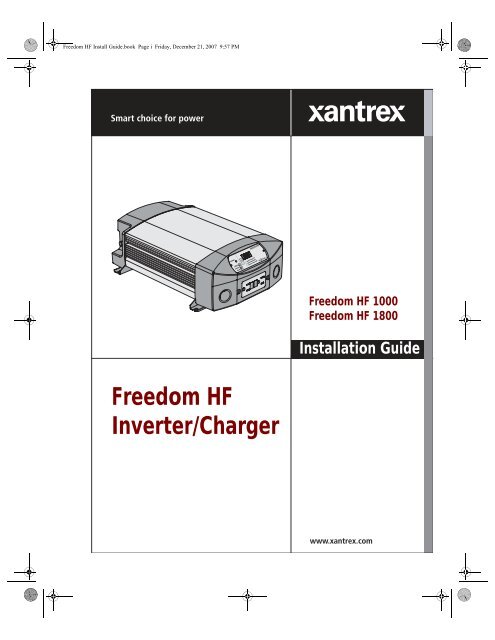
<strong>Freedom</strong> <strong>HF</strong> Install <strong>Guide</strong>.book Page v Friday, December 21, 2007 9:57 PMImportant Safety InstructionsIMPORTANT: Read and save this <strong>Installation</strong> <strong>Guide</strong>for future reference.This chapter contains important safety and installation instructionsfor the <strong>Freedom</strong> <strong>HF</strong> <strong>Inverter</strong>/<strong>Charger</strong> units–<strong>Freedom</strong> <strong>HF</strong> 1000 and<strong>Freedom</strong> <strong>HF</strong> 1800.WARNING: Limitations on useThe <strong>Freedom</strong> <strong>HF</strong> is not intended for use in connection with life support systemsor other medical equipment or devices.1. BEFORE INSTALLING AND USING THE FREEDOM <strong>HF</strong>, READ ALLINSTRUCTIONS AND CAUTIONARY MARKINGS ON THE FREEDOM <strong>HF</strong>,THE BATTERIES, AND ALL APPROPRIATE SECTIONS OF THIS GUIDE.CAUTION: Risk of injuryTo reduce the risk of injury, charge only 12 Vdc lead-acid (GEL, AGM, andFlooded) rechargeable batteries. Other battery types may burst, causing personalinjury and damage.2. Do not expose the <strong>Freedom</strong> <strong>HF</strong> to rain, snow, spray, or bilge water.To reduce risk of fire hazard, do not cover or obstruct the ventilationopenings. Do not install the <strong>Freedom</strong> <strong>HF</strong> in a zero-clearancecompartment. Overheating may result.3. To avoid a risk of fire and electric shock, make sure that existingwiring is in good condition and that wire is not undersized. Do notoperate the <strong>Freedom</strong> <strong>HF</strong> with damaged or substandard wiring.4. The use of any attachments not recommended or sold by <strong>Xantrex</strong>,may result in risk of fire, electric shock, or injury to persons.5. Do not operate the <strong>Freedom</strong> <strong>HF</strong> if it has received a sharp blow, beendropped, or otherwise damaged in any way. If the <strong>Freedom</strong> <strong>HF</strong> isdamaged, see the Warranty section.vThis guide for use by qualified installers only
<strong>Freedom</strong> <strong>HF</strong> Install <strong>Guide</strong>.book Page vi Friday, December 21, 2007 9:57 PM6. Do not disassemble the <strong>Freedom</strong> <strong>HF</strong>. It contains no user-serviceableparts. See Warranty for instructions on obtaining service. Attemptingto service the <strong>Freedom</strong> <strong>HF</strong> yourself may result in a risk of electricalshock or fire and will void your warranty. Internal capacitors remaincharged after all power is disconnected.7. To reduce the risk of electrical shock, disconnect both AC and DCpower from the <strong>Freedom</strong> <strong>HF</strong> before attempting any maintenance orcleaning or working on any circuits connected to the <strong>Freedom</strong> <strong>HF</strong>.Turning off controls will not reduce this risk.8. The <strong>Freedom</strong> <strong>HF</strong> must be provided with an equipment-groundingconductor connected to the AC input ground.WARNING: Explosion hazard1. WORKING IN THE VICINITY OF BATTERIES IS DANGEROUS. BATTERIESGENERATE EXPLOSIVE GASES DURING NORMAL OPERATION.THEREFORE, IT IS OF UTMOST IMPORTANCE THAT EACH TIME BEFORESERVICING THE UNIT IN THE VICINITY OF THE BATTERY, THAT YOUREAD THIS MANUAL AND FOLLOW THE INSTRUCTIONS EXACTLY.2. This equipment contains components which tend to produce arcs orsparks. To prevent fire or explosion, do not install the <strong>Freedom</strong> <strong>HF</strong> incompartments containing batteries or flammable materials, or inlocations that require ignition-protected equipment. This includes anyspace containing gasoline-powered machinery, fuel tanks, as well asjoints, fittings, or other connections between components of the fuelsystem.3. To reduce the risk of battery explosion, follow these instructions andthose published by the battery manufacturer and the manufacturer ofany unit you intend to use in the vicinity of the battery.vi 975-0395-01-01This guide for use by qualified installers only
<strong>Freedom</strong> <strong>HF</strong> Install <strong>Guide</strong>.book Page vii Friday, December 21, 2007 9:57 PMPersonal Precautions When Working With BatteriesWARNING: BATTERIES PRESENT RISK OF ELECTRICAL SHOCK,BURN FROM HIGH SHORT-CIRCUIT CURRENT, FIRE OREXPLOSION FROM VENTED GASES. OBSERVE PROPERPRECAUTIONS.1. Study and follow all of the battery manufacturer's specificprecautions, such as removing or not removing cell caps whilecharging, and recommended rates of charge.2. Add distilled water in each cell until battery acid reaches the levelspecified by the battery manufacturer. This helps to purge excessivegas from cells. Do not overfill. For a battery without cell caps,carefully follow manufacturer's recharging instructions.3. Make sure the area around the battery is well ventilated.4. Never smoke or allow a spark or flame near the engine or batteries.5. Use extra caution to reduce the risk or dropping a metal tool on thebattery. It could spark or short circuit the battery or other electricalparts and could cause an explosion.6. Remove all metal items, like rings, bracelets, and watches whenworking with batteries. Batteries can produce a short circuit currenthigh enough to weld metal to skin, causing a severe burn.7. Have someone within range of your voice or close enough to come toyour aid when you work near a lead-acid battery.8. Have plenty of fresh water and soap nearby in case battery acidcontacts skin, clothing, or eyes.9. Wear complete eye protection and clothing protection. Avoidtouching your eyes while working near batteries.10. If battery acid contacts skin or clothing, wash immediately with soapand water. If acid enters your eye, immediately flood it with runningcold water for at least twenty minutes and get medical attentionimmediately.11. If you need to remove a battery, always remove the ground terminalfrom the battery first. Make sure all accessories are off so you don’tcause an arc.975-0395-01-01 viiThis guide for use by qualified installers only
<strong>Freedom</strong> <strong>HF</strong> Install <strong>Guide</strong>.book Page ix Friday, December 21, 2007 9:57 PMPrecautions for Using Rechargeable AppliancesCAUTION: Equipment damageMost rechargeable battery-operated equipment uses a separate charger ortransformer that is plugged into an AC receptacle and produces a lowvoltage charging output.Some chargers for small rechargeable batteries can be damaged ifconnected to the <strong>Freedom</strong> <strong>HF</strong>. Do not use the following with the <strong>Freedom</strong><strong>HF</strong>:• Small battery-operated appliances like flashlights, razors, and nightlights that can be plugged directly into an AC receptacle to recharge.• Some chargers for battery packs used in power hand tools. Theseaffected chargers display a warning label stating that dangerousvoltages are present at the battery terminals.Important: If you are unsure about using your rechargeable appliance withthe <strong>Freedom</strong> <strong>HF</strong>, contact the equipment manufacturer to find out if the applianceis acceptable for use with modified sine wave input voltage. See the detaileddescription of the <strong>Freedom</strong> <strong>HF</strong> waveform in Appendix A, “Specifications” under“Electrical Specifications: <strong>Inverter</strong> Mode” on page A–2.975-0395-01-01 ixThis guide for use by qualified installers only
<strong>Freedom</strong> <strong>HF</strong> Install <strong>Guide</strong>.book Page x Friday, December 21, 2007 9:57 PMx 975-0395-01-01This guide for use by qualified installers only
<strong>Freedom</strong> <strong>HF</strong> Install <strong>Guide</strong>.book Page xi Friday, December 21, 2007 9:57 PMContentsImportant Safety Instructions - - - - - - - - - - - - - - - - - - - - - - - - - - - - - - - - - - -v1 <strong>Installation</strong>Materials List- - - - - - - - - - - - - - - - - - - - - - - - - - - - - - - - - - - - - - - - - - - - - - - - - 1–2Safety Instructions - - - - - - - - - - - - - - - - - - - - - - - - - - - - - - - - - - - - - - - - - - - - - 1–3<strong>Installation</strong> Codes - - - - - - - - - - - - - - - - - - - - - - - - - - - - - - - - - - - - - - - - - - - 1–3<strong>Installation</strong> Tools and Materials - - - - - - - - - - - - - - - - - - - - - - - - - - - - - - - - - - - - 1–4High Level Overview of <strong>Installation</strong> Steps - - - - - - - - - - - - - - - - - - - - - - - - - - - - - 1–4Basic <strong>Installation</strong> Procedures - - - - - - - - - - - - - - - - - - - - - - - - - - - - - - - - - - - - - - 1–5Step 1: Designing the <strong>Installation</strong> - - - - - - - - - - - - - - - - - - - - - - - - - - - - - - - - 1–6Step 2: Choosing a Location for the <strong>Freedom</strong> <strong>HF</strong> - - - - - - - - - - - - - - - - - - - - 1–12Step 3: Mounting the <strong>Freedom</strong> <strong>HF</strong> - - - - - - - - - - - - - - - - - - - - - - - - - - - - - - 1–13Connecting the Equipment Ground - - - - - - - - - - - - - - - - - - - - - - - - - - - 1–14Grounding Locations - - - - - - - - - - - - - - - - - - - - - - - - - - - - - - - - - - - - - 1–14Step 4: Connecting the AC Input Wires - - - - - - - - - - - - - - - - - - - - - - - - - - - 1–15General AC Wiring Considerations - - - - - - - - - - - - - - - - - - - - - - - - - - - 1–15AC Input Connections - - - - - - - - - - - - - - - - - - - - - - - - - - - - - - - - - - - - 1–16Step 5: Connecting AC Output to an Existing AC Circuit - - - - - - - - - - - - - - - 1–19Step 6: Connecting the DC Cables - - - - - - - - - - - - - - - - - - - - - - - - - - - - - - 1–24DC Grounding - - - - - - - - - - - - - - - - - - - - - - - - - - - - - - - - - - - - - - - - - 1–27Step 7: Mounting the Display Panel - - - - - - - - - - - - - - - - - - - - - - - - - - - - - 1–28Step 8: Testing Your <strong>Installation</strong> - - - - - - - - - - - - - - - - - - - - - - - - - - - - - - - - 1–29Testing in Invert Mode - - - - - - - - - - - - - - - - - - - - - - - - - - - - - - - - - - - 1–29Testing in Shore Power Mode - - - - - - - - - - - - - - - - - - - - - - - - - - - - - - - 1–30Drip Shield <strong>Installation</strong> (For Marine <strong>Installation</strong>s) - - - - - - - - - - - - - - - - - - - - - - - 1–312. ConfigurationSetting Battery Types on the Main Unit - - - - - - - - - - - - - - - - - - - - - - - - - - - - - - - 2–2Adjusting Display, Alarm, and Charging Current Settings- - - - - - - - - - - - - - - - - - - 2–3975-0395-01-01 xiThis guide for use by qualified installers only
<strong>Freedom</strong> <strong>HF</strong> Install <strong>Guide</strong>.book Page xii Friday, December 21, 2007 9:57 PMABSpecificationsElectrical Specifications: <strong>Inverter</strong> Mode- - - - - - - - - - - - - - - - - - - - - - - - - - - - - - -A–2Electrical Specifications: Charge Mode - - - - - - - - - - - - - - - - - - - - - - - - - - - - - - -A–3Environmental Specifications - - - - - - - - - - - - - - - - - - - - - - - - - - - - - - - - - - - - - -A–4System Specifications - - - - - - - - - - - - - - - - - - - - - - - - - - - - - - - - - - - - - - - - - - -A–4Physical Specifications - - - - - - - - - - - - - - - - - - - - - - - - - - - - - - - - - - - - - - - - - -A–4Regulatory Approvals - - - - - - - - - - - - - - - - - - - - - - - - - - - - - - - - - - - - - - - - - - -A–4<strong>Inverter</strong> Overload Operation- - - - - - - - - - - - - - - - - - - - - - - - - - - - - - - - - - - - - - -A–5Invert Power Derating vs. Ambient Temperature - - - - - - - - - - - - - - - - - - - - - - - - -A–6<strong>Charger</strong> Output Current vs. AC Input Voltage- - - - - - - - - - - - - - - - - - - - - - - - - - -A–7Marine <strong>Installation</strong> DiagramMarine <strong>Installation</strong> - - - - - - - - - - - - - - - - - - - - - - - - - - - - - - - - - - - - - - - - - - - - - B–2xiiThis guide for use by qualified installers only
<strong>Freedom</strong> <strong>HF</strong> Install <strong>Guide</strong>.book Page xiii Friday, December 21, 2007 9:57 PMFiguresFigure 1-1 What’s In The Box - - - - - - - - - - - - - - - - - - - - - - - - - - - - - - - - - - - - - 1–2Figure 1-2 Typical Recreational Vehicle and Fleet Vehicle <strong>Installation</strong> - - - - - - - - - - 1–6Figure 1-3 Approved Mounting Orientations- - - - - - - - - - - - - - - - - - - - - - - - - - - - 1–13Figure 1-4 DC Panel Connections - - - - - - - - - - - - - - - - - - - - - - - - - - - - - - - - - - - 1–14Figure 1-5 <strong>Freedom</strong> <strong>HF</strong> AC Wiring Compartment - - - - - - - - - - - - - - - - - - - - - - - - 1–17Figure 1-6 AC Wiring Diagram with an <strong>Inverter</strong> Subpanel - - - - - - - - - - - - - - - - - - 1–22Figure 1-7 AC Wiring Diagram without an <strong>Inverter</strong> Subpanel - - - - - - - - - - - - - - - - 1–23Figure 1-8 DC End - - - - - - - - - - - - - - - - - - - - - - - - - - - - - - - - - - - - - - - - - - - - - 1–24Figure 1-9 DC Cable Connections- - - - - - - - - - - - - - - - - - - - - - - - - - - - - - - - - - - 1–27Figure 1-10 Drip Shields - - - - - - - - - - - - - - - - - - - - - - - - - - - - - - - - - - - - - - - - - - 1–31Figure 1-11 Typical Drip Shield Placement on a <strong>Freedom</strong> <strong>HF</strong> 1800 - - - - - - - - - - - - - 1–32Figure 2-1 Dip Switches (Default Settings Shown) - - - - - - - - - - - - - - - - - - - - - - - 2–2Figure 2-2 Display Panel - - - - - - - - - - - - - - - - - - - - - - - - - - - - - - - - - - - - - - - - - 2–3Figure B-1 Typical Marine <strong>Installation</strong> - - - - - - - - - - - - - - - - - - - - - - - - - - - - - - - - B–3975-0395-01-01 xiiiThis guide for use by qualified installers only
<strong>Freedom</strong> <strong>HF</strong> Install <strong>Guide</strong>.book Page xiv Friday, December 21, 2007 9:57 PMxivThis guide for use by qualified installers only
<strong>Freedom</strong> <strong>HF</strong> Install <strong>Guide</strong>.book Page xv Friday, December 21, 2007 9:57 PMTablesTable 1-1 Required AC Wire Size vs Breaker Rating - - - - - - - - - - - - - - - - - - - - - 1–9Table 1-2 Recommended Cable Sizes - - - - - - - - - - - - - - - - - - - - - - - - - - - - - - - - 1–10Table 1-3 Recommended Equipment Ground Cable size - - - - - - - - - - - - - - - - - - - 1–14Table 1-4 Required AC wire size vs. required breaker rating - - - - - - - - - - - - - - - - 1–16Table 1-5 Color codes for typical AC wiring - - - - - - - - - - - - - - - - - - - - - - - - - - - 1–16Table 2-1 Charging Current <strong>Guide</strong>lines- - - - - - - - - - - - - - - - - - - - - - - - - - - - - - - 2–5Table A-1 Charging Voltage - - - - - - - - - - - - - - - - - - - - - - - - - - - - - - - - - - - - - - A–7975-0395-01-01 xvThis guide for use by qualified installers only
<strong>Freedom</strong> <strong>HF</strong> Install <strong>Guide</strong>.book Page xvi Friday, December 21, 2007 9:57 PMxviThis guide for use by qualified installers only
<strong>Freedom</strong><strong>HF</strong>_IC_01-<strong>Installation</strong>.fm Page 1 Monday, December 24, 2007 9:47 AM1 <strong>Installation</strong>Chapter 1 provides information to help in installing a<strong>Freedom</strong> <strong>HF</strong> <strong>Inverter</strong>/<strong>Charger</strong> <strong>Installation</strong>.It covers the following:• Materials list.• Safety instructions and various installation codesthat may be applicable to your installation.• Sample installation tools and materials.• High level overview of installation steps.• <strong>Installation</strong> procedures starting on page 1–5including mounting and connecting the equipmentground, AC cabling, DC cabling, and groundingsteps.• Drip shields installation (For Marine <strong>Installation</strong>s).This guide for use by qualified installers only1–1
<strong>Freedom</strong><strong>HF</strong>_IC_01-<strong>Installation</strong>.fm Page 2 Monday, December 24, 2007 9:47 AMMaterials ListYour <strong>Freedom</strong> <strong>HF</strong> <strong>Inverter</strong>/<strong>Charger</strong> package includes the items listedbelow.• 1 <strong>Freedom</strong> <strong>HF</strong> <strong>Inverter</strong>/<strong>Charger</strong> unit• 1 Display panel with 7-inch (0.17 m) cable• 1 Communications cable (25 feet) (7.5 m)• 2 DC terminal covers• 2 Strain-relief clamps (for AC input and output wiring)• 1 Blanking plate• 2 Reference materials–an Owner’s <strong>Guide</strong> and an <strong>Installation</strong> <strong>Guide</strong>• 1 Set of mounting templates• 1 Set of lock washers and nuts (not shown)<strong>Freedom</strong> <strong>HF</strong> unitDisplay panel isattached to the unit.Owner’s <strong>Guide</strong><strong>Installation</strong> <strong>Guide</strong>mounting templateblanking platestrain-relief clampscommunications cableDC terminal coversFigure 1-1 What’s In The Box1–2 975-0395-01-01This guide for use by qualified installers only
<strong>Freedom</strong><strong>HF</strong>_IC_01-<strong>Installation</strong>.fm Page 3 Monday, December 24, 2007 9:47 AMSafety InstructionsSafety Instructions<strong>Installation</strong> CodesWARNING: Shock hazard<strong>Xantrex</strong> Technology recommends that all wiring be done by a certified technicianor electrician to ensure adherence to the applicable electrical safety wiringregulations.• Before you begin the installation, review the “Important SafetyInstructions” on page v, and read this entire “<strong>Installation</strong>” section soyou can plan your installation from beginning to end.• Disconnect all AC and DC power sources to prevent accidentalshock. Disable and secure all AC and DC disconnect devices andautomatic generator starting devices.Governing installation codes vary depending on the specific location andapplication of the installation. Some examples include the following:• The U.S. National Electrical Code (NEC)• The Canadian Electrical Code (CEC)• The U.S. Code of Federal Regulations (CFRs)• Canadian Standards Association (CSA) and the RV IndustryAssociation (RVIA) for installations in RVs• The American Boating and Yachting Committee (ABYC) for Marineinstallations in the U.S.It is the installer’s responsibility to ensure that all applicable installationrequirements are met.975-0395-01-01 1–3This guide for use by qualified installers only
<strong>Freedom</strong><strong>HF</strong>_IC_01-<strong>Installation</strong>.fm Page 4 Monday, December 24, 2007 9:47 AM<strong>Installation</strong> Tools and MaterialsYou will need the following to install the <strong>Freedom</strong> <strong>HF</strong>:❐❐❐❐❐❐❐❐❐❐Wire stripperMounting screws or bolts#2 Phillips screwdriverWrench for DC terminals (1/2 inch or 13mm or adjustable)AC cable (i.e. 2-conductor-plus-ground cable), sized appropriatelyfor load and applicationWire nuts or crimp connectors for AC wire and appropriate toolsTwo 1/2 inch strain-relief clamps (supplied) for AC cablesDC cable, sized appropriately for load and applicationLugs for DC cables to fit 8 mm (5/16 in.) DC stud terminals) as wellas appropriate tools (e.g. crimping tool)AC and DC disconnects and over-current protective devicesHigh Level Overview of <strong>Installation</strong> StepsInstalling the <strong>Freedom</strong> <strong>HF</strong> includes the following steps.1. Ensure that AC and DC power are both OFF.2. Mount the inverter securely and permanently in one of the acceptableorientations.3. Connect the Equipment Grounding Terminal to the equipment groundbus.4. Connect the AC input wiring to the AC source panel.5. Connect the AC output wiring to the AC load panel.6. Connect one end of the DC negative cable to the negative of thebattery, and the other to the negative terminal of the unit.7. Install an appropriately sized fuse and DC disconnect in the positivecable.8. Connect the DC positive cable to the positive of the battery, and to thepositive terminal of the unit.9. Close the DC disconnect switch.Do not proceed with installation until you have read “Safety Instructions”on page 1–3.1–4 975-0395-01-01This guide for use by qualified installers only
<strong>Freedom</strong><strong>HF</strong>_IC_01-<strong>Installation</strong>.fm Page 8 Monday, December 24, 2007 9:47 AMAC Output: The circuit breaker or fuse must be rated at no more thanthe rating of the input breaker in the installation and must beapproved for use on 120 Vac branch circuits. The wire used betweenthe <strong>Freedom</strong> <strong>HF</strong> and the AC output breaker must be of adequate sizeto match the AC input circuit breaker’s rating. The wiring from eachAC output breaker to each of the loads must be adequately sized tocarry the current rating of the individual AC output breaker.Disconnect Devices: Each system requires a method ofdisconnecting the AC circuits. If the over-current protection devicesare circuit breakers, they will also serve as the disconnects. If fusesare used, separate AC disconnect switches will be needed ahead ofthe fuses. These will have to be a branch circuit rated for 120 Vac andhave an appropriate current rating.AC DistributionPanelsMost systems incorporate distribution centers both ahead of the <strong>Freedom</strong><strong>HF</strong> (the AC source panel) and between the <strong>Freedom</strong> <strong>HF</strong> and the loads (theAC load panel). An AC source panel includes a main circuit breaker,which serves as over-current protection and as a disconnect for the ACshore power supply line. Additional circuit breakers serve individualcircuits, one of which serves the <strong>Freedom</strong> <strong>HF</strong>. The AC load panel canincorporate an AC output circuit breaker and breakers for individual loadcircuits.CAUTION: Equipment damageDo not connect the output of the <strong>Freedom</strong> <strong>HF</strong> to what is known as a “multi-wirebranch circuit”. These are four-wire circuits consisting of a ground, neutral, andtwo lines that are 180 degrees out of phase with each other (from a standard 120/240V “split phase” circuit). These circuits are commonly used in kitchens topower “split receptacles” where the top and bottom halves of a duplex receptacleare connected to different lines.AC CablingAC cabling includes all the wires and connectors between the AC sourceand the <strong>Freedom</strong> <strong>HF</strong>, as well as all cabling between the <strong>Freedom</strong> <strong>HF</strong> andthe AC output panels, circuit breakers, and loads. The type and size of thewiring varies with the installation and load. For example, in highvibration environments, such as marine or RV applications, wire nuts maynot be acceptable, so crimp splices would be required. In otherapplications, flexible multiple-strand wire may be required. <strong>Installation</strong>codes usually specify solid or stranded, overall size of the conductors, andtype and temperature rating of the insulation around the wire.1–8 975-0395-01-01This guide for use by qualified installers only
<strong>Freedom</strong><strong>HF</strong>_IC_01-<strong>Installation</strong>.fm Page 9 Monday, December 24, 2007 9:47 AMBasic <strong>Installation</strong> ProceduresAC breakers and fuses must be sized to adequately protect the wiring thatis installed on the input and output AC circuits of the <strong>Freedom</strong> <strong>HF</strong>. Allbreakers and wiring must be sized and connected in accordance with theelectrical codes or regulations applicable to your installation. Table 1-1gives some examples of wiring sizes based on the U.S. National ElectricalCode and the Canadian Electrical Code. These examples are based onusing a 2-conductor-plus-ground cable rated at 75 °C, and assuming anambient temperature of up to 30 °C. Ensure that your breakers, and fuseshave suitable temperature ratings for your wiring. Other codes andregulations may also be applicable to your installation.Table 1-1 Required AC Wire Size vs Breaker RatingBreaker Size 10A 15A 20A 30AMinimum Wire Size 14AWG 14AWG 12AWG 10AWGAC OutputNeutralBondingDC CablingThe neutral conductor of the <strong>Freedom</strong> <strong>HF</strong>’s AC output circuit (i.e., ACOutput Neutral) is automatically connected to the safety ground duringinverter operation. When AC utility power is present and the <strong>Freedom</strong> <strong>HF</strong>is charging, this connection is not present, so that the utility neutral (i.e.,AC Input Neutral) is only connected to utility ground at your source. Thisconforms to National Electrical Code, which requires that separatelyderived AC sources (such as inverters and generators) to have theirneutral conductors tied to ground in the same way that the neutralconductor from the utility is tied to ground in only one place. Check theregulations for your specific application to ensure that the installation willcomply with the necessary requirements. In other words, the AC InputNeutral and Output Neutral must be isolated from each other.This includes all the cables and connectors between the batteries, the DCdisconnect and over-current protection device, and the <strong>Freedom</strong> <strong>HF</strong>. Mostmobile installations require multi-strand insulated cables for flexibilityand durability in high vibration environments and require disconnects andover-current devices. Electrical wiring sizes are indicated by AWGnotation. Under the AWG standard, a larger gauge number indicates asmaller wire diameter. Wire size is usually marked on the larger sizedcables. Table 1-2 specifies the minimum recommended DC cable size andmaximum fuse size for the <strong>Freedom</strong> <strong>HF</strong>. The DC cables must be copperand must be rated 75 °C minimum. The cables should be terminatedwith lugs that fit the DC stud terminals snugly (8 mm or 5/16 in. holesize).975-0395-01-01 1–9This guide for use by qualified installers only
<strong>Freedom</strong><strong>HF</strong>_IC_01-<strong>Installation</strong>.fm Page 10 Monday, December 24, 2007 9:47 AMTable 1-2 Recommended Cable Sizes<strong>Inverter</strong>/<strong>Charger</strong>Cable Length: Batteryto <strong>Inverter</strong> (one way)<strong>Freedom</strong> <strong>HF</strong> 1000 Less than 5 feet (1.5meters)<strong>Freedom</strong> <strong>HF</strong> 1800 Less than 5 feet (1.5meters)Minimum Cable SizeNo. 2 AWGNo. 2/0 AWGMaximum battery FuseSize150 Adc250 AdcNote: <strong>Xantrex</strong> recommends not using a cable longer than 5 feet (1.5 meters) in each direction. Cablesizes above are based on the US National Electrical Code Table 310.17 - 75C cables, assuming anambient temperature of 30 °C cables.Important: Using the correct cable size is critical to achieving the ratedperformance of the <strong>Freedom</strong> <strong>HF</strong> unit. When starting a heavy load the <strong>Freedom</strong><strong>HF</strong> can draw current surges from the battery of up to 400A. If the DC wiring istoo small the voltage drop from this surge will result in a voltage at the <strong>Freedom</strong><strong>HF</strong> terminals that is too low for the <strong>Freedom</strong> <strong>HF</strong> to operate correctly. The<strong>Freedom</strong> <strong>HF</strong> may appear to operate correctly with smaller cables until a heavyload such as a microwave or refrigerator attempts to start - then the unit maywork correctly sometimes and not work correctly other times.DC Disconnectsand Over-Current DevicesBatteriesThe DC circuit from the battery to the <strong>Freedom</strong> <strong>HF</strong> must be equippedwith a disconnect and over-current device. This usually consists of acircuit breaker, a “fused-disconnect,” or a separate fuse and DCdisconnect. Do not confuse AC circuit breakers with DC circuit breakers.They are not interchangeable. The rating of the fuse or breaker must bematched to the size of cables used in accordance with the applicableinstallation codes. The breaker or disconnect and fuse should be locatedas close as possible to the battery, in the positive cable. Applicable codesmay limit how far the protection can be from the battery.The <strong>Freedom</strong> <strong>HF</strong> uses 12-volt battery banks. Every <strong>Freedom</strong> <strong>HF</strong> systemrequires a deep-cycle battery or group of batteries that provide the DCcurrent that the <strong>Freedom</strong> <strong>HF</strong> converts to AC.1–10 975-0395-01-01This guide for use by qualified installers only
<strong>Freedom</strong><strong>HF</strong>_IC_01-<strong>Installation</strong>.fm Page 11 Monday, December 24, 2007 9:47 AMBasic <strong>Installation</strong> ProceduresGround FaultCircuitInterrupters(GFCIs)A GFCI is a device that de-energizes a circuit when a current to groundexceeds a specified value that is less than that required to blow the circuitbreaker. GFCIs are intended to protect people from electric shocks andare usually required in wet or damp locations.<strong>Installation</strong>s in marine and recreational vehicles require GFCI protectionof branch circuits connected to the AC output of the <strong>Freedom</strong> <strong>HF</strong>.The modified sine wave output of the <strong>Freedom</strong> <strong>HF</strong> is not equivalent to thewaveform provided by electric utilities, and compliance with UL andCSA standards requires that <strong>Xantrex</strong> test and recommend specific GFCIsthat will work correctly with the <strong>Freedom</strong> <strong>HF</strong>.For more information about GFCIs, see the application note "Using GFCIReceptacles on <strong>Xantrex</strong> <strong>Inverter</strong>s and <strong>Inverter</strong>/<strong>Charger</strong>s" in the DocumentLibrary at www.xantrex.com/support.975-0395-01-01 1–11This guide for use by qualified installers only
<strong>Freedom</strong><strong>HF</strong>_IC_01-<strong>Installation</strong>.fm Page 12 Monday, December 24, 2007 9:47 AMStep 2: Choosing a Location for the <strong>Freedom</strong> <strong>HF</strong>WARNING: Fire and explosion hazardThis equipment contains components that tend to produce arcs or sparks. Toprevent fire or explosion, do not install the <strong>Freedom</strong> <strong>HF</strong> in compartmentscontaining batteries or flammable materials, or in locations that require ignitionprotectedequipment. This includes any space containing gasoline-poweredmachinery, fuel tanks, or joints, fittings, or other connections betweencomponents of the fuel system.WARNING: Fire hazardTo reduce the risk of fire, do not cover or obstruct the ventilation openings. Donot install the <strong>Freedom</strong> <strong>HF</strong> in a zero-clearance compartment. Overheating mayresult.The <strong>Freedom</strong> <strong>HF</strong> should only be installed in locations that meet thefollowing requirements:❐ Dry. Do not allow water or other fluids to drip or splash on the<strong>Freedom</strong> <strong>HF</strong>. Do not mount the <strong>Freedom</strong> <strong>HF</strong> in an area subject tosplashing water or bilge water.❐ Cool. Normal air temperature should be between 32 °F and 104 °F(0 °C and 40 °C)—the cooler the better.❐ Ventilated. Allow at least 5 in. (13cm) of clearance at the DC end ofthe <strong>Freedom</strong> <strong>HF</strong> for air flow, 1 in. (2.5cm) on each side, and 2 in.(5cm) at the AC end. The more clearance for ventilation around theunit, the better the performance. Do not allow the ventilationopenings on the ends of the unit to become obstructed.❐ Safe. Do not install the <strong>Freedom</strong> <strong>HF</strong> in the same compartment asbatteries or in any compartment capable of storing flammable liquidslike gasoline.❐ Close to the battery compartment and the AC source and loadpanels. Avoid excessive cable lengths (which reduce input and outputpower due to wire resistance). Use the recommended cable lengthsand sizes, especially between the battery banks and the <strong>Freedom</strong> <strong>HF</strong>.❐ Protected from battery acid and gases. Never allow battery acid todrip on the <strong>Freedom</strong> <strong>HF</strong> or its wiring when reading specific gravity orfilling the battery. Also do not mount the unit where it will beexposed to gases produced by the batteries. These gases are verycorrosive, and prolonged exposure will damage the <strong>Freedom</strong> <strong>HF</strong>.1–12 975-0395-01-01This guide for use by qualified installers only
<strong>Freedom</strong><strong>HF</strong>_IC_01-<strong>Installation</strong>.fm Page 13 Monday, December 24, 2007 9:47 AMBasic <strong>Installation</strong> ProceduresStep 3: Mounting the <strong>Freedom</strong> <strong>HF</strong>To mount the <strong>Freedom</strong> <strong>HF</strong>:1. Remove the <strong>Freedom</strong> <strong>HF</strong> from its shipping container, verify that allcomponents are present, and record relevant product information on“Information About Your System” on page WA–4.2. Select an appropriate mounting location and orientation. (See Figure1-3 below.) To meet regulatory requirements, for use in on-landapplications, the <strong>Freedom</strong> <strong>HF</strong> must be mounted in one of thefollowing orientations:• Under a horizontal surface (see 1)• In a horizontal position on a vertical surface (see 2)Note: For marine installations, only this orientation is allowed,due to the probability of moisture finding access into theenclosure.• On a horizontal surface (see 3)12See page 1–31 for dripshield installation onMarine applications.3Figure 1-3 Approved Mounting Orientations3. Look for the mounting template and unfold. Tape it to the mountingsurface and pilot-drill the desired number of mounting holes. Removethe template.4. Fasten the <strong>Freedom</strong> <strong>HF</strong> to the mounting surface. If you are mountingthe unit on a wall or bulkhead, use #12 or #14 pan-head wood or sheetmetal screws to secure it to the framing behind the wall or bulkhead.Alternatively, use nut inserts and 1/4-20 machine screws.975-0395-01-01 1–13This guide for use by qualified installers only
<strong>Freedom</strong><strong>HF</strong>_IC_01-<strong>Installation</strong>.fm Page 14 Monday, December 24, 2007 9:47 AMConnecting the Equipment GroundWARNING: Fire hazardNever operate the <strong>Freedom</strong> <strong>HF</strong> without properly connecting the equipmentground. A fire hazard could result from improper grounding.The <strong>Freedom</strong> <strong>HF</strong> has a ground stud on the side of the unit as shown inFigure 1-4. Follow the guidelines in “Grounding Locations” to connectthe inverter’s chassis to the ground.Equipmentground studGrounding LocationsFigure 1-4 DC Panel ConnectionsYou must connect the equipment ground stud to a grounding point—usually the vehicle’s chassis or DC negative bus ground—usingrecommended copper wire (if insulated then green insulation with orwithout one or more yellow stripes) or larger.For recommended equipment ground cable size, see below.Table 1-3 Recommended Equipment Ground Cable sizeMinimum equipment ground cable sizeApplication(Stranded cable is recommended)Recreational Vehicle a No. 8 AWGMarine bNo. 3 AWG (<strong>Freedom</strong> <strong>HF</strong> 1000)No. 1/0 AWG (<strong>Freedom</strong> <strong>HF</strong> 1800)Note: There are no restrictions on length for the equipment ground cable.a.Based on US National Electrical Code NFPA70, Article 551, par. 551-20c 2005version.b.Based on ABYC E-11 11.18 dated 07/03In general, the equipment ground cable size must not be smaller than oneAWG size than the supply cable.1–14 975-0395-01-01This guide for use by qualified installers only
<strong>Freedom</strong><strong>HF</strong>_IC_01-<strong>Installation</strong>.fm Page 15 Monday, December 24, 2007 9:47 AMBasic <strong>Installation</strong> ProceduresStep 4: Connecting the AC Input WiresGeneral AC Wiring ConsiderationsWARNING: Fire, Shock and Energy hazardsMake sure wiring is disconnected from all electrical sources before handling. Allwiring must be done in accordance with local and national electrical wiringcodes. Do not connect the output terminals of the <strong>Freedom</strong> <strong>HF</strong> to any incomingAC source.AC WiringConnectorsAC and DCWiringSeparationAC WiringCompartmentAC Wiring andGFCIsConnect AC wires with crimp-on splice connectors.The amount of insulation you strip off individual wires will be specifiedby the connector manufacturer and is different for different types ofconnectors.Do not mix AC and DC wiring in the same conduit or panel. Where DCand AC wires must cross, make sure they do so at 90° to one another.Consult applicable codes for details about DC and AC wiring in closeproximity to each other.For your reference, the AC Wiring Compartment is shown in Figure 1-5.You can plug loads (12 A continuous, 15 A maximum) directly into theGFCI receptacle on the front panel of the <strong>Freedom</strong> <strong>HF</strong>. You can alsoconnect the inverter to an existing AC installation and then plug loads intoGFCI receptacles connected to that circuit.If you plan to use the <strong>Freedom</strong> <strong>HF</strong> with the GFCI installed on the unit,proceed to “Step 6: Connecting the DC Cables” on page 1–24.If you plan to hard wire the <strong>Freedom</strong> <strong>HF</strong> AC input and output to anexisting AC installation, read this section.AC wiring includes all the wires and connectors between the AC sourceand the <strong>Freedom</strong> <strong>HF</strong> and all wiring between the inverter, the AC panels,circuit breakers, and the GFCIs. The type and size of the wiring varieswith the installation and load. For some RV applications, flexiblemultiple-strand wire is required.975-0395-01-01 1–15This guide for use by qualified installers only
<strong>Freedom</strong><strong>HF</strong>_IC_01-<strong>Installation</strong>.fm Page 16 Monday, December 24, 2007 9:47 AMAC wiring must be sized appropriately to carry full load current on theinput and output AC circuits in accordance with the electrical codes orregulations applicable to your installation. Table 1-4 is based on the U.S.National Electrical Code, 2003 Ed. and the Canadian Electrical Code,assuming 2-conductor-plus-ground cable, using 75 °C wiring, at anambient temperature of 30 °C. Other codes and regulations may beapplicable to your installation.Table 1-4 Required AC wire size vs. required breaker ratingRequired Breaker Size Required Wire Size<strong>Freedom</strong> <strong>HF</strong> 30 A maximum 10 AWGThere are two knockouts on the front panel for AC input and outputwiring. Use the supplied strain relief clamps to prevent damage to thewiring from tension being applied.AC Input ConnectionsCAUTION: Equipment damageThe AC wiring terminal block is split into input and output sections. Damage tothe inverter will occur if the unit is wired incorrectly.When making the AC input and AC output connections, observe thecorrect color code for the appropriate AC wire, as described in Table 1-5.Table 1-5 Color codes for typical AC wiringColorAC WireBlack or Brown LineWhite or Blue NeutralGreen, Green/Yellow, Groundor bare copper1. Ensure that AC and DC power are both OFF.2. Install the required circuit breaker in the AC output panel supplyingthe unit (See Figure 1-6 on page 1–22).3. Remove the screws securing the GFCI AC receptacle and remove itfrom the front panel.4. Disconnect the GFCI wiring, if desired.1–16 975-0395-01-01This guide for use by qualified installers only
<strong>Freedom</strong><strong>HF</strong>_IC_01-<strong>Installation</strong>.fm Page 17 Monday, December 24, 2007 9:47 AMBasic <strong>Installation</strong> Procedures5. Remove the left-hand side AC wiring knockout from the front panelof the unit (see Figure 1-5 on page 1–17).6. Install one of the supplied strain-relief clamps in the AC knockout.7. Locate the terminal block.The two input terminals are labeled as follows:• AC Input (L)• AC Input (N)A separate screw is provided to connect the AC input ground (seeFigure 1-5 on page 1–17).AC inputground screwS TATUSU til ityBatterySelectInpu t Voltag e ( V )Inpu t Cu rre nt (A)AC outputground screwFaultOutpu t Pow er (W )AC knockoutFREEDOM <strong>HF</strong> 1000AC knockoutN L GNDAC INPUTN L GNDAC OUTPUTCAUTION! Do not connect the AC OUT to anyother source of power . Damage to unit may occur .Figure 1-5 <strong>Freedom</strong> <strong>HF</strong> AC Wiring Compartment8. Strip about 2 inches (50 mm) from the jacket of the AC input cable.The AC input cable may be either solid or stranded (as required), butmust have three conductors and be sized as in Table 1-4 on page 1–16.(The AC terminal block accepts wire sizes up to No. 10 AWG.)9. Strip approximately 3/8 inch (10 mm) from the insulation of eachconductor.10. Run the AC cable through the right-hand side strain-relief clamp andinto the wiring compartment.11. Fasten the Ground wire to the grounding screw.12. Using the 1/8 inch slot screwdriver, loosen the wire attachmentscrews on the terminals.CAUTION: Reverse polarityImproper connections (connecting a line conductor to a neutral conductor, forexample) will cause the <strong>Freedom</strong> <strong>HF</strong> to malfunction and may permanentlydamage the inverter. Damage caused by a reverse polarity connection is notcovered by your warranty.975-0395-01-01 1–17This guide for use by qualified installers only
<strong>Freedom</strong><strong>HF</strong>_IC_01-<strong>Installation</strong>.fm Page 18 Monday, December 24, 2007 9:47 AM13. Insert the Line and Neutral wires into the corresponding terminals.14. Tighten the wire attachment screws to a torque of 1.3–1.8 lbf-ft(1.76–2.44 Nm). Leave some wiring slack inside the wiringcompartment.15. Secure the AC cable by adjusting the strain-relief clamps.If you do not plan to proceed with “Step 5: Connecting AC Output toan Existing AC Circuit” on page 1–19, follow the succeeding substep.16. Install the GFCI back into the front panel of the unit.Alternatively, if you do not reinstall the GFCI, make sure that you capthe exposed wires and install a blanking plate to cover the spacevacated by the GFCI.1–18 975-0395-01-01This guide for use by qualified installers only
<strong>Freedom</strong><strong>HF</strong>_IC_01-<strong>Installation</strong>.fm Page 19 Monday, December 24, 2007 9:47 AMStep 5: Connecting AC Output to an Existing AC CircuitBasic <strong>Installation</strong> ProceduresWARNING: Shock, fire, and energy hazardsMake sure wiring is disconnected from all electrical sources before handling. Allwiring must be done in accordance with applicable local and national electricalwiring codes.WARNING: Shock hazard and equipment damageDo not connect any AC source (such as a generator or utility power) to theAC wiring output of the <strong>Freedom</strong> <strong>HF</strong>.The <strong>Freedom</strong> <strong>HF</strong> will not operate if its output is connected to AC voltage fromanother source, and potentially hazardous or damaging conditions may occur.These conditions can occur even if the inverter is off.Do not connect the <strong>Freedom</strong> <strong>HF</strong> to an AC branch circuit that hashigh-power consumption loads.The <strong>Freedom</strong> <strong>HF</strong> will not operate electric heaters, air conditioners, stoves,and other electrical appliances that consume more than 1000 watts(<strong>Freedom</strong> <strong>HF</strong> 1000) or 1800 watts (<strong>Freedom</strong> <strong>HF</strong> 1800).A <strong>Xantrex</strong>-tested and approved GFCI must be connected to the <strong>Freedom</strong><strong>HF</strong> AC output, and on every receptacle connected to the AC hard wiredinstallation. Other types may fail to operate properly when connected tothe <strong>Freedom</strong> <strong>HF</strong>. Although you can reuse the factory-installed GFCI,<strong>Xantrex</strong> has also tested and approved the following GFCIs for use withthe <strong>Freedom</strong> <strong>HF</strong>:MakeModelHubbell GFR5252Leviton 65988598For more information about GFCIs, see the application note “Using GFCIReceptacles on <strong>Xantrex</strong> <strong>Inverter</strong>s and <strong>Inverter</strong>/<strong>Charger</strong>s” in the DocumentLibrary at www.xantrex.com.975-0395-01-01 1–19This guide for use by qualified installers only
<strong>Freedom</strong><strong>HF</strong>_IC_01-<strong>Installation</strong>.fm Page 20 Monday, December 24, 2007 9:47 AMWARNING: Shock, fire, and energy hazardsMake sure wiring is disconnected from all electrical sources before handling. Allwiring must be done in accordance with applicable local and national electricalwiring codes. Do not connect the output leads of the inverter to any incoming ACsource.To make a permanent connection to existing AC wiring (continuingfrom # 15 of “Step 4: Connecting the AC Input Wires” on page 1–15):1. Ensure that AC and DC power are both OFF.2. Install the required value of circuit breaker in the AC load panel (seeFigure 1-6 on page 1–22 and Figure 1-7 on page 1–23).3. Remove the left-hand side AC wiring knockout from the front of theunit.Important: The applicable installation code may not allow you to run the ACIN and AC OUT wiring through the same AC knockout.4. Install one of the supplied strain-relief clamps in the AC knockout.5. Locate the terminal block.The two output terminals are labeled as follows:• AC Output (L)• AC Output (N)A separate screw is provided to connect the AC output ground.6. Strip about 2 inches (50 mm) from the jacket of the AC output cable.The AC output cable may be either solid or stranded (as required), butmust have three conductors and sized as in Table 1-4 on page 1–16.(The AC terminal block accepts wire sizes up to No. 10 AWG.)7. Strip approximately 3/8 inch (10 mm) off the insulation of eachconductor.8. Run the AC cable through the left-hand side strain-relief clamp andinto the wiring compartment.9. Fasten the Ground wire to the grounding screw.10. Using the 1/8 inch slot screwdriver, loosen the wire attachmentscrews on the terminals.1–20 975-0395-01-01This guide for use by qualified installers only
<strong>Freedom</strong><strong>HF</strong>_IC_01-<strong>Installation</strong>.fm Page 21 Monday, December 24, 2007 9:47 AMBasic <strong>Installation</strong> ProceduresCAUTION: Reverse polarityImproper connections (connecting a line conductor to a neutral conductor, forexample) will cause the <strong>Freedom</strong> <strong>HF</strong> to malfunction and may permanentlydamage the inverter. Damage caused by a reverse polarity connection is notcovered by your warranty.11. Insert the Line and Neutral wires into the corresponding terminals.12. Tighten the wire attachment screws to a torque of 1.3–1.8 lbf-ft(1.76–2.44 Nm). Leave some wiring slack inside the wiringcompartment.Ensure you have maintained correct polarity and that there are noloose strands of wire.13. Secure the cable by adjusting the strain-relief clamps.14. Install the GFCI back into the front panel of the unit.Alternatively, if you do not reinstall the GFCI, make sure that you capthe exposed wires and install a blanking plate to cover the spacevacated by the GFCI.15. Connect the outgoing AC wires to the AC load panel.975-0395-01-01 1–21This guide for use by qualified installers only
<strong>Freedom</strong><strong>HF</strong>_IC_01-<strong>Installation</strong>.fm Page 22 Monday, December 24, 2007 9:47 AMCAUTION: Equipment damageDo NOT connect the AC OUT Neutral and Lineto the AC IN Neutral and Line.See Important note below.See Importantnote below.See Importantnote below.Figure 1-6 AC Wiring Diagram with an <strong>Inverter</strong> SubpanelIn this wiring diagram, the AC input to the <strong>Freedom</strong> <strong>HF</strong> comes from themain AC panel which contains the input circuit breaker. The AC outputwiring is routed to a separate inverter subpanel with a dedicated circuitbreaker.Important: The generator must have its neutral bonded to ground. If it is notbonded, a bonding jumper must be installed between the neutral and ground atthe generator’s output or at the generator side of the transfer switch.Also, both the main AC panel and the inverter subpanel must not have apermanent neutral to ground bonds installed.1–22 975-0395-01-01This guide for use by qualified installers only
<strong>Freedom</strong><strong>HF</strong>_IC_01-<strong>Installation</strong>.fm Page 23 Monday, December 24, 2007 9:47 AMBasic <strong>Installation</strong> ProceduresCAUTION: Equipment damageDo NOT connect the AC OUT Neutral and Lineto the AC IN Neutral and Line.See Important note below.See Importantnote below.Input breakers mustbe provided byinstallers.Figure 1-7 AC Wiring Diagram without an <strong>Inverter</strong> SubpanelIn this wiring diagram, the AC input to the <strong>Freedom</strong> <strong>HF</strong> comes directlyfrom an AC source. The AC source input wiring must be protected by anAC breaker of 30 A max. The output wiring is routed to the main ACpanel which is also protected by AC breakers or circuit breakers.Important: The generator must have its neutral bonded to ground. If it is notbonded, a bonding jumper must be installed between the neutral and ground atthe generator’s output or at the generator side of the transfer switch.Also, the main AC panel must not have a permanent neutral to ground bondinstalled.975-0395-01-01 1–23This guide for use by qualified installers only
<strong>Freedom</strong><strong>HF</strong>_IC_01-<strong>Installation</strong>.fm Page 24 Monday, December 24, 2007 9:47 AMStep 6: Connecting the DC CablesCAUTIONBefore making the final DC connection, check cable polarity at both the batteryand the <strong>Freedom</strong> <strong>HF</strong>. Positive must be connected to positive; negative must beconnected to negative.Reversing the positive and negative battery cables will damage the <strong>Freedom</strong> <strong>HF</strong>and void your warranty. This type of damage is easily detected.WARNING: Fire hazardUse only copper wire rated 75 °C minimum. Make sure all DC connections aretight to a torque of 216–240 inch-pounds (24–27Nm). Loose connections willoverheat.Follow the procedure given below to connect the battery leads to theterminals on the DC end. The cables should be as short as possible andlarge enough to handle the required current, in accordance with theelectrical codes or regulations applicable to your installation. Table 1-2 onpage 1–10 specifies the minimum DC cable size and maximum fuse sizefor the <strong>Freedom</strong> <strong>HF</strong>.Do not route your DC cables through an electrical distribution panel,battery isolator, or other device that will cause additional voltage drops.Figure 1-8 shows the DC end for your reference.Figure 1-8 DC End1–24 975-0395-01-01This guide for use by qualified installers only
<strong>Freedom</strong><strong>HF</strong>_IC_01-<strong>Installation</strong>.fm Page 25 Monday, December 24, 2007 9:47 AMBasic <strong>Installation</strong> ProceduresTo make the DC connectionsRefer to Figure 1-9.1. Make sure the inverter is off and no AC or DC is connected to theunit.2. Remove the nuts and washers from the <strong>Freedom</strong> <strong>HF</strong> positive andnegative DC terminals.3. Strip 1/2 inch (13 mm) to 3/4 inch (19 mm) insulation from one endof each cable. The amount stripped off will depend on the terminalschosen.4. Attach the connectors that will secure the cables to the battery, to thedisconnect/battery selector switch, and the fuse block. The connectorsyou use must create a permanent, low-resistance connection.If crimp connectors are required, <strong>Xantrex</strong> recommends usingapproved and certified connectors, and to use the tool recommendedby the terminal manufacturer. Make sure no stray wires protrude fromthe connector or terminal.(You may find it more convenient to have the crimp connectorsattached by the company that sells you the cable and/or connectors.)5. For each cable end that will be connected to the inverter, strip 1/2inch (13 mm) to 3/4 inch (19 mm) of insulation from the cable. Theamount stripped off will depend on the terminals chosen.6. Thread a supplied DC terminal cover over the positive and negativecables. The red cover goes on the positive cable; the black cover onthe negative cable.7. Attach the connector that will join the cable to the inverter DCterminal.8. Install a fuse and fuse holder in the cable that will be used for thepositive side of the DC circuit.The fuse must:• be as close to the battery positive terminal as possible,• be rated for DC circuits,• have an Ampere Interrupting Capacity (AIC) that exceeds theshort-circuit current available from the battery (i.e., Class T fuse).975-0395-01-01 1–25This guide for use by qualified installers only
<strong>Freedom</strong><strong>HF</strong>_IC_01-<strong>Installation</strong>.fm Page 26 Monday, December 24, 2007 9:47 AM9. To prevent sparking when making the connection, ensure thedisconnect/battery selector switch is off.10. Attach the connector on the positive cable to the positive DC terminalon the inverter.11. Install the lock washer and nut that are supplied with the inverter.Tighten the nut to a torque of 108–120 in-lbf (12.2–13.6 N-m). Makethe connection snug enough so the ring terminal does not movearound on the DC terminal, but do not overtighten. See Figure 1-9,“DC Cable Connections” on page 1–27.CAUTIONLoose connections cause excessive voltage drop and may cause overheated wiresand melted insulation.CAUTIONDo not over-tighten the nut on the DC input terminals. Damage to the DC inputterminals may result.The maximum torque setting is 120 in-lbf (13.6 N-m).CAUTION: Reverse polarityDC power connections to the <strong>Freedom</strong> <strong>HF</strong> must be positive to positive andnegative to negative.A reverse polarity connection (positive to negative) will blow a fuse in theinverter and may permanently damage the inverter. The fuse is not userreplaceable and the inverter may need to be returned for servicing.Damage caused by a reverse polarity connection is not covered by your warranty..12. Before proceeding, double check that the cable you have just installedconnects the positive DC terminal of the inverter to the disconnect/battery selector switch, fuse holder, and that the other end of the fuseholder is connected to the positive terminal of the battery.WARNING: Explosion or fireDo not complete the next step if flammable fumes are present. Explosion or firemay result if the disconnect/battery selector switch is not in the off position.Thoroughly ventilate the battery compartment before making this connection.13. Connect the cable from the negative post of the battery to the negativeDC terminal of the inverter.1–26 975-0395-01-01This guide for use by qualified installers only
<strong>Freedom</strong><strong>HF</strong>_IC_01-<strong>Installation</strong>.fm Page 27 Monday, December 24, 2007 9:47 AMBasic <strong>Installation</strong> Procedures14. Install the lock washer and nut that are supplied. Tighten the nut to atorque of 108–120 in-lbf (12.2–13.6 N-m). Make the connection snugenough so the ring terminal does not move around on the DCterminal, but do not overtighten.15. Slip the DC terminal covers over the <strong>Freedom</strong> <strong>HF</strong> DC terminals.Figure 1-9 DC Cable ConnectionsDC GroundingTo connect the DC ground:The equipment grounding lug on the DC end of the <strong>Freedom</strong> <strong>HF</strong> is usedto connect the chassis of the <strong>Freedom</strong> <strong>HF</strong> to your system’s DC negativeconnection or grounding bus point as required by electrical regulations.Use copper wire that is either bare or provided with green insulation. Donot use the DC Ground Lug for your AC grounding. (See the AC wiringinstructions in this section.)Follow the guidelines below that correspond to the specific type ofinstallation. These guidelines assume you are using the DC supply cableand fuse sizes recommended in this manual. If you are using differentsizes, refer to the applicable installation code for DC grounding details.• Recreational Vehicle Use 8AWG copper wire and connect itbetween the Chassis Ground lug and the vehicle’s DC groundingpoint (usually the vehicle chassis or a dedicated DC ground bus).• Marine Use copper wire that is bare or has insulation rated min.105 °C, and connect it between the Chassis Ground lug and the boat’sDC grounding bus or engine negative bus. For the <strong>Freedom</strong> <strong>HF</strong> 1000,use a wire of gauge 4AWG minimum. For the <strong>Freedom</strong> <strong>HF</strong> 1800, usea wire of gauge 1/0AWG minimum.975-0395-01-01 1–27This guide for use by qualified installers only
<strong>Freedom</strong><strong>HF</strong>_IC_01-<strong>Installation</strong>.fm Page 28 Monday, December 24, 2007 9:47 AMStep 7: Mounting the Display PanelThe communications cable supplied with the display panel is 25 feet (7.62meters) long. If you want to replace the cable with one that is shorter, usea high quality, 6-wire telephone extension cable.Flush mounting the panel on a wall, bulkhead, or panel requires anopening that is approximately 3.25 × 1.25 inches (8.25 × 3.18 cm). About1.5 inches (3.81 cm) of free space is required within the wall toaccommodate the depth of the panel. Be sure there is no wiring or otherobstructions within the wall before you make an opening.To mount the display panel:1. Choose a location that is dry, out of direct sunlight, free fromcorrosive or explosive fumes, and otherwise appropriate for mountingan electronic device.2. Tape the mounting template (in the <strong>Freedom</strong> <strong>HF</strong> package) to themounting surface and mark the locations of the mounting holes andthe area to be cut away.3. Pilot-drill the mounting holes and cut out the hole in which the panelwill be inserted.4. Route the communications cable(s) inside the wall and through theopening.5. Insert one of the cable’s connectors in either jack on the bottom of thepanel.6. Place the panel in the opening and secure it with appropriatefasteners.7. Route the communications cable to the <strong>Freedom</strong> <strong>HF</strong> and insert theconnector in the jack located near the battery select dip switch.Important: Do not route the communications cable in parallel and in conduitwith the AC and DC wires. In situations where the cable must cross with the ACand DC wires, make sure they cross at a 90° angle to each other.1–28 975-0395-01-01This guide for use by qualified installers only
<strong>Freedom</strong><strong>HF</strong>_IC_01-<strong>Installation</strong>.fm Page 29 Monday, December 24, 2007 9:47 AMBasic <strong>Installation</strong> ProceduresStep 8: Testing Your <strong>Installation</strong>WARNING: Shock hazardPressing the <strong>Inverter</strong> button to turn OFF the <strong>Freedom</strong> <strong>HF</strong> inverter function ondisplay panel does not disconnect DC or AC input power to the <strong>Freedom</strong> <strong>HF</strong>. Ifshore power is present at AC input terminals, it will pass through to the ACoutput.There are two tests to be performed. The first test verifies that the<strong>Freedom</strong> <strong>HF</strong> is inverting DC battery power and delivering AC power toits output.The second test is intended for installations where AC input and output ishard wired to the <strong>Freedom</strong> <strong>HF</strong>. This test verifies that the <strong>Freedom</strong> <strong>HF</strong>transfers from inverter power to shore power when shore power ispresent.Testing in Invert ModeNote: Shore power (pass-through) refers to the AC input power from a utilitygrid, generator or external AC source.When you are ready to test your installation and operate the <strong>Freedom</strong> <strong>HF</strong>,close the DC fuse and Disconnect or the DC circuit breaker to supply DCpower to the <strong>Freedom</strong> <strong>HF</strong>.To test the <strong>Freedom</strong> <strong>HF</strong> in invert mode:1. For hard wired installations, ensure shore power is not present.2. Press the <strong>Inverter</strong> button to turn the inverter on.The status LED on the display panel glows yellow and the LEDdisplay illuminates.3. Plug an appliance within the power rating of the inverter into the<strong>Freedom</strong> <strong>HF</strong> GFCI or an AC outlet hard wired to the <strong>Freedom</strong> <strong>HF</strong>.4. Turn the appliance on to verify that it operates.If the appliance operates, your installation is successful. If yourinstallation has AC input and output hard wired to the <strong>Freedom</strong> <strong>HF</strong>,proceed to “Testing in Shore Power Mode”.If the status LED on the display panel glows red, see the Troubleshootingchapter.975-0395-01-01 1–29This guide for use by qualified installers only
<strong>Freedom</strong><strong>HF</strong>_IC_01-<strong>Installation</strong>.fm Page 30 Monday, December 24, 2007 9:47 AMTesting in Shore Power ModeTo test the <strong>Freedom</strong> <strong>HF</strong> in shore power mode:◆With the appliance from the previous test still connected andoperating, connect the shore power source.The <strong>Freedom</strong> <strong>HF</strong> transfers the appliances to shore power. The statusLED on the display panel will change from yellow to a ten-secondflashing yellow and then green.If the appliance operates, your installation is successful.Note: If the <strong>Inverter</strong> button on the <strong>Freedom</strong> <strong>HF</strong> is turned ON, the <strong>Freedom</strong> <strong>HF</strong>will automatically supply the appliances with inverter power if the shore powersource fails or becomes disconnected.If the <strong>Inverter</strong> button on the <strong>Freedom</strong> <strong>HF</strong> is turned ON and shore power voltage istoo low (less than 90 volts AC), the unit will transfer to inverter power to continuerunning your appliances.WARNING: Shock hazardWhether or not the <strong>Inverter</strong> button is turned ON, shore power will pass throughthe <strong>Freedom</strong> <strong>HF</strong> to the output when shore power is within normal operatingrange.1–30 975-0395-01-01This guide for use by qualified installers only
<strong>Freedom</strong><strong>HF</strong>_IC_01-<strong>Installation</strong>.fm Page 31 Monday, December 24, 2007 9:47 AMDrip Shield <strong>Installation</strong> (For Marine <strong>Installation</strong>s)Drip Shield <strong>Installation</strong> (For Marine <strong>Installation</strong>s)The drip shield helps to protect the unit from dripping or splashingliquids, which will cause a shock hazard. Drip shields are especiallyuseful in marine installations where water from condensation, rain, or seamay come into contact with the <strong>Freedom</strong> <strong>HF</strong>.WARNING: Shock hazardThis product is intended only for use in dry areas. Operating the unit under wetconditions may expose you to a shock hazard. Installing drip shields may notentirely protect you from this hazard. Do not operate the unit when it is wet.You may purchase the drip shield set by contacting <strong>Xantrex</strong>. Whenordering, mention part number 808-9531.Different Views)Figure 1-10 Drip ShieldsDrip Shield set part# 808-9531To install the drip shields:1. Gather the four screws needed to fasten a single drip shield to a wall.2. Locate an appropriate setting for the drip shields above the <strong>Freedom</strong><strong>HF</strong> making sure you cover the entire width of the unit.You can overlay the shields as shown in Figure 1-11 below.975-0395-01-01 1–31This guide for use by qualified installers only
<strong>Freedom</strong><strong>HF</strong>_IC_01-<strong>Installation</strong>.fm Page 32 Monday, December 24, 2007 9:47 AM3. Fasten the screws through the holes in the drip shield into the wall.See Figure 1-10.FREEDOM<strong>HF</strong> | 1000Figure 1-11 Typical Drip Shield Placement on a <strong>Freedom</strong> <strong>HF</strong> 18001–32 975-0395-01-01This guide for use by qualified installers only
<strong>Freedom</strong><strong>HF</strong>_IC_02-Configuration.fm Page 1 Monday, December 24, 2007 9:48 AM2 ConfigurationChapter 2 explains how to configure the <strong>Freedom</strong> <strong>HF</strong> tobest meet your electrical system requirements.It covers the following:• Setting battery types on the main unit on page 2–2.• Adjusting display, alarm, and charging currentsettings on page 2–3.This guide for use by qualified installers only2–1
<strong>Freedom</strong><strong>HF</strong>_IC_02-Configuration.fm Page 2 Monday, December 24, 2007 9:48 AMSetting Battery Types on the Main UnitYou can attach different types of lead-acid batteries to the <strong>Freedom</strong> <strong>HF</strong>.Before installing batteries make sure that you configure the unit tooptimize the charging process.WARNING: Fire hazardIncorrectly setting the battery type can lead to battery damage and a risk of fire.The settings can be changed by adjusting the dip switches found on themain unit behind the display panel.BatteryTypeDip Switch SettingSwitch 1|Switch 2Bulk/AbsorptionFloatFixed OFF|OFF 13.5 13.5Flooded OFF|ON (default) 14.4 13.5GEL ON|OFF 14.2 13.8AGM ON|ON 14.3 13.4To adjust the battery type setting:By default the battery type is set to Flooded (OFF|ON) .1. Detach the Display Panel to expose the Dip Switches.2. Use the tip of your fingernail or a small screw driver with a flat tip toadjust the switches.OFFONSwitch 1 | Switch 2Figure 2-1 Dip Switches (Default Settings Shown)2–2 975-0395-01-01This guide for use by qualified installers only
<strong>Freedom</strong><strong>HF</strong>_IC_02-Configuration.fm Page 3 Monday, December 24, 2007 9:48 AMAdjusting Display, Alarm, and Charging Current SettingsAdjusting Display, Alarm, and Charging CurrentSettingsThe two display panel buttons can be used to adjust the following:• What is being displayed on the screen,• To disable or enable the audible alarm, and• To change the charging current.FREEDOMSTATUSUtilityInput Voltage (V)BatteryFaultSelectInput Current (A)Output Power (kW)<strong>HF</strong> 1000Figure 2-2 Display PanelTo adjust what is being displayed on the screen:By default the screen displays the Input Voltage value in Volts and theInput Voltage LED is illuminated.1. Press the Select button once.The display will show the DC Input Current and the DC InputCurrent LED will illuminate.The value is displayed on the screen as Amps.2. Press the Select button once again.The display will show the AC Output Power and the AC OutputPower LED will illuminate.The value is displayed on the screen as kWatts.3. Press the Select button once again.The display will show the DC Input Voltage and the DC InputVoltage LED will illuminate.The value is displayed on the screen as Volts.975-0395-01-01 2–3This guide for use by qualified installers only
<strong>Freedom</strong><strong>HF</strong>_IC_02-Configuration.fm Page 4 Monday, December 24, 2007 9:48 AMTo adjust the alarm setting:By default the alarm is set to ON.• Press and hold the Select button for two seconds.The display shows “AL0” indicating that the alarm is OFF.The display shows “AL1” indicating that the alarm is ON.Whenever the alarm setting is changed, the display will temporarily showeither “AL0” or “AL1” and after a few seconds will return to displayingwhat was on the screen prior to the adjustment.Note: The alarm setting will reset to its default setting when the<strong>Freedom</strong> <strong>HF</strong>’s <strong>Inverter</strong> button is turned OFF then turned ONagain.To adjust the charging current:By default the charging current is set to:• 20A for the <strong>Freedom</strong> <strong>HF</strong> 1000• 40A for the <strong>Freedom</strong> <strong>HF</strong> 18001. Press and hold the <strong>Inverter</strong> button for five seconds.The unit will go into Charge Current Setting Mode.2. Press the Select button to toggle between the different Amp ratings.• 2 — 5 — 10 — 20 for the <strong>Freedom</strong> <strong>HF</strong> 1000• 2 —10 — 20 — 40 for the <strong>Freedom</strong> <strong>HF</strong> 18003. Choose the desired charging current by stopping at the value shownon the display. To maximize unit performance, see Table 2-1“Charging Current <strong>Guide</strong>lines” below.Wait for five seconds and the charging current is set.2–4 975-0395-01-01This guide for use by qualified installers only
<strong>Freedom</strong><strong>HF</strong>_IC_02-Configuration.fm Page 5 Monday, December 24, 2007 9:48 AMAdjusting Display, Alarm, and Charging Current SettingsAfter the charging current is set, the display will return to displaying whatwas on the screen prior to the adjustment.Table 2-1 Charging Current <strong>Guide</strong>linesAC Input CircuitBreaker or fusesize (Amps)<strong>Charger</strong> DC Current Setting(Amps)Maximum By-pass ACCurrent Available (Amps)<strong>Freedom</strong> <strong>HF</strong> 1000 <strong>Freedom</strong> <strong>HF</strong> 1800 <strong>Freedom</strong> <strong>HF</strong> 1000 <strong>Freedom</strong> <strong>HF</strong> 180015 2 2 13.5 13.55 10 12.5 11.010 20 11.0 8.520 40 8.5 3.520 2 2 18.5 18.55 10 17.5 1610 20 16 13.520 40 13.5 8.530 2 2 28.5 28.55 10 27.5 2610 20 26 23.520 40 23.5 18.5975-0395-01-01 2–5This guide for use by qualified installers only
<strong>Freedom</strong><strong>HF</strong>_IC_02-Configuration.fm Page 6 Monday, December 24, 2007 9:48 AM2–6
<strong>Freedom</strong><strong>HF</strong>_IC_A-Specifications.fm Page 1 Monday, December 24, 2007 9:48 AMASpecificationsAppendix A contains electrical performanceinformation and product specifications.Important: Specifications are subject to change without notice.This guide for use by qualified installers onlyA–1
<strong>Freedom</strong><strong>HF</strong>_IC_A-Specifications.fm Page 2 Monday, December 24, 2007 9:48 AMElectrical Specifications: <strong>Inverter</strong> ModeDC Input <strong>Freedom</strong> <strong>HF</strong> 1000 <strong>Freedom</strong> <strong>HF</strong> 1800Operating voltage range 10.5V–15.5V 10.5V–15.5VSafe non-operating voltage range 0–16 Vdc 0–16 VdcNormal voltage 12.5V 12.5VNominal current at full load 100A 180AAC Output <strong>Freedom</strong> <strong>HF</strong> 1000 <strong>Freedom</strong> <strong>HF</strong> 1800Output voltage 115 Vac 115 VacContinuous power 1.0kW @ 25 °C 1.8kW @ 25 °CSurge power17A(2kW for 200 ms)30A(3.6kW for 300 ms)Max short-circuit current 55A peak 55A peakFrequency 60 Hz 60 HzWave shape Modified Sinewave Modified SinewavePower derating above 40 °C ambienttempSee “Invert Power Derating vs. AmbientTemperature” on page A–6.Peak efficiency ≥87% ≥87%Full load efficiency ≥80% ≥80%Other <strong>Freedom</strong> <strong>HF</strong> 1000 <strong>Freedom</strong> <strong>HF</strong> 1800No load input power (producingoutput voltage)≤10W≤10WOff mode current draw ≤1mA ≤1mAA–2 975-0395-01-01This guide for use by qualified installers only
<strong>Freedom</strong><strong>HF</strong>_IC_A-Specifications.fm Page 3 Monday, December 24, 2007 9:48 AMElectrical Specifications: Charge ModeElectrical Specifications: Charge ModeAC Input <strong>Freedom</strong> <strong>HF</strong> 1000 <strong>Freedom</strong> <strong>HF</strong> 1800Operating voltage range 90–130 Vac 90–130 VacNominal current5Aac at 20A charge, 10Aac at 40A120 Vac in charge, 120 Vac inNominal frequency 60 Hz 60 HzDC Output <strong>Freedom</strong> <strong>HF</strong> 1000 <strong>Freedom</strong> <strong>HF</strong> 1800Nominal voltage 12.0 Vdc 12.0 VdcMin battery voltage for charging 0.0 Vdc 0.0 VdcMax output voltage 14.4 Vdc 14.4 VdcNominal output currentUser selectable:2A, 5A, 10A, 20AUser selectable:2A, 10A, 20A, 40A<strong>Charger</strong> current deratingAutomatically reduce charger current asinternal temperature exceeds 80 °C, andinput Vac approaches low transfer.Efficiency at nominal output ≥75% ≥75%Other <strong>Freedom</strong> <strong>HF</strong> 1000 <strong>Freedom</strong> <strong>HF</strong> 1800Battery type settingsCharge algorithmsFlooded (default), Gel, AGM, orFixed (13.5V)Three stages (Bulk, Absorption, and Float)Independent battery banks 1 1975-0395-01-01 A–3This guide for use by qualified installers only
<strong>Freedom</strong><strong>HF</strong>_IC_A-Specifications.fm Page 4 Monday, December 24, 2007 9:48 AMEnvironmental SpecificationsAmbient Temperature:Operating Temperature RangeStorage Temperature RangeHumidity: Operation/Storage0–40 ºC-20–60 ºC, with output derated above 25 °C-40–70 ºC5–95% RH, non-condensingSystem SpecificationsTransfer relay ratingTransfer timeTransfer on bad voltageCooling30A, 2.0hp
<strong>Freedom</strong><strong>HF</strong>_IC_A-Specifications.fm Page 5 Monday, December 24, 2007 9:48 AM<strong>Inverter</strong> Overload Operation<strong>Inverter</strong> Overload OperationThis graph shows how long (measured in seconds) the <strong>Freedom</strong> <strong>HF</strong> willoperate for a given output current (measured in Amps).Both <strong>Freedom</strong> <strong>HF</strong> 1000 and <strong>Freedom</strong> <strong>HF</strong> 1800 are represented in theillustration below.The graph illustrates inverter operation at 25 °C.Time (sec)<strong>Freedom</strong> <strong>HF</strong> 1000<strong>Freedom</strong> <strong>HF</strong> 18004000...1600140012001000800600400200010 12 14 16 18 20 30 40 50Output Current (Amps)975-0395-01-01 A–5This guide for use by qualified installers only
<strong>Freedom</strong><strong>HF</strong>_IC_A-Specifications.fm Page 6 Monday, December 24, 2007 9:48 AMInvert Power Derating vs. Ambient TemperatureIf the unit is in inverter mode and in elevated ambient temperature above25 °C, you will have to reduce power draw according to the followingchart to avoid over-temperature shutdown.<strong>Freedom</strong> <strong>HF</strong> 1000Watts1000@ 12.5 V30 °C900@ 11.5 V~33 °C900 W800 W750 W750850 W025 30 35 40 4550 °C<strong>Freedom</strong> <strong>HF</strong> 1800Watts1800@ 12.5 V30 °C1600@ 11.5 V~33 °C1450 W1100 W1000 W10001350 W025 30 35 40 4550 °CA–6 975-0395-01-01This guide for use by qualified installers only
<strong>Freedom</strong><strong>HF</strong>_IC_A-Specifications.fm Page 7 Monday, December 24, 2007 9:48 AM<strong>Charger</strong> Output Current vs. AC Input Voltage<strong>Charger</strong> Output Current vs. AC Input VoltageWhen the <strong>Freedom</strong> <strong>HF</strong> is charging batteries from a weak shore powersource the AC voltage may fall as the <strong>Freedom</strong> <strong>HF</strong> draws current. Toreduce the chance of the shore power voltage collapsing below theconfigured transfer level the <strong>Freedom</strong> <strong>HF</strong> will reduce the charging currentat low shore power voltage according to the following graph:<strong>Freedom</strong> <strong>HF</strong> 1000 <strong>Freedom</strong> <strong>HF</strong> 180020A16A40A32A90V 105V 135VTable A-1 Charging VoltageBattery Type Bulk/Absorption (Volts) Float (Volts)Flooded 14.4 13.5GEL 14.2 13.8AGM 14.3 13.4Fixed 13.5 13.5975-0395-01-01 A–7This guide for use by qualified installers only
<strong>Freedom</strong><strong>HF</strong>_IC_A-Specifications.fm Page 8 Monday, December 24, 2007 9:48 AMA–8
<strong>Freedom</strong> <strong>HF</strong> Install <strong>Guide</strong>.book Page 1 Friday, December 21, 2007 9:57 PMBMarine <strong>Installation</strong> DiagramAppendix B illustrates a typical marine installation forthe <strong>Freedom</strong> <strong>HF</strong>.For a typical RV or Fleet installation, see Figure 1-2,“Typical Recreational Vehicle and Fleet Vehicle<strong>Installation</strong>” on page 1–6.This guide for use by qualified installers onlyB–1
<strong>Freedom</strong> <strong>HF</strong> Install <strong>Guide</strong>.book Page 2 Friday, December 21, 2007 9:57 PMMarine <strong>Installation</strong>Figure B-1 illustrates a typical marine installation with the followingcomponents:1. AC power supplied from a shore power connector2. An AC source panel that includes a Max 30A circuit breaker thatsupplies the <strong>Freedom</strong> <strong>HF</strong>3. An AC load panel with branch circuit breakers that supply only loadsthat run off the <strong>Freedom</strong> <strong>HF</strong>4. Engine negative bus / DC ground bus5. DC power supplied by a battery bank and protected by a DC fuse inthe positive cable6. Battery isolator7. DC alternator8. Starting battery9. Drip shield (not shown)B–2 975-0395-01-01This guide for use by qualified installers only
<strong>Freedom</strong> <strong>HF</strong> Install <strong>Guide</strong>.book Page 3 Friday, December 21, 2007 9:57 PMMarine <strong>Installation</strong>FR EE D O MH F | 100012V Deep CycleBatteryDC Fuse /disconnect orcircuit breakerAC Load PanelAC Source PanelStarting BatteryShorepowerFigure B-1 Typical Marine <strong>Installation</strong>975-0395-01-01 B–3This guide for use by qualified installers only
<strong>Freedom</strong> <strong>HF</strong> Install <strong>Guide</strong>.book Page 4 Friday, December 21, 2007 9:57 PMB–4
<strong>Freedom</strong> <strong>HF</strong> Install <strong>Guide</strong>.book Page 5 Friday, December 21, 2007 9:57 PM
<strong>Freedom</strong> <strong>HF</strong> Install <strong>Guide</strong>.book Page 6 Friday, December 21, 2007 9:57 PM<strong>Xantrex</strong> Technology Inc.1 800 670 0707 Tel toll free NA1 408 987 6030 Tel direct1 800 994 7828 Fax toll free NAcustomerservice@xantrex.comwww.xantrex.com975-0395-01-01 Printed in China