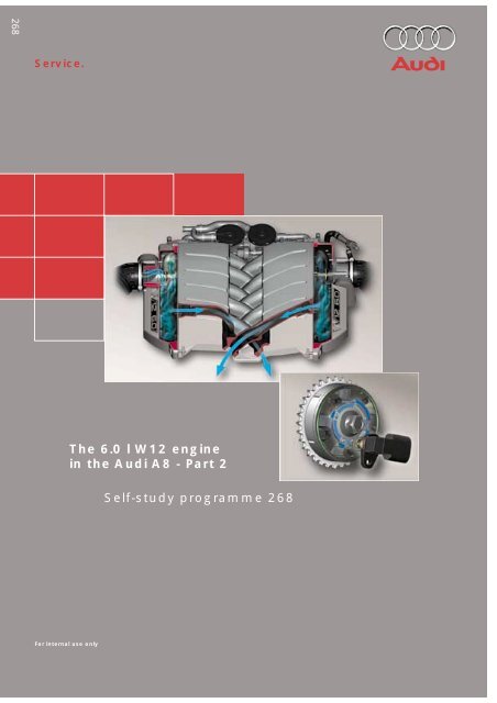
The 6.0 l W12 engine in the Audi A8 - Part 2 Self-study ... - Volkspage
The 6.0 l W12 engine in the Audi A8 - Part 2 Self-study ... - Volkspage
The 6.0 l W12 engine in the Audi A8 - Part 2 Self-study ... - Volkspage
Create successful ePaper yourself
Turn your PDF publications into a flip-book with our unique Google optimized e-Paper software.
ContentsEng<strong>in</strong>e, MechanicsPageBelt drive/ancillaries . . . . . . . . . . . . . . . . . . . . . . . . . . . . . . . . . . . . . . . . . . . . . . . . . . . 3Water-cooled alternator . . . . . . . . . . . . . . . . . . . . . . . . . . . . . . . . . . . . . . . . . . . . . . . . 4Hydraulic/electric fan control . . . . . . . . . . . . . . . . . . . . . . . . . . . . . . . . . . . . . . . . . . . 6Hydraulic fan circuit . . . . . . . . . . . . . . . . . . . . . . . . . . . . . . . . . . . . . . . . . . . . . . 6Power steer<strong>in</strong>g circuit . . . . . . . . . . . . . . . . . . . . . . . . . . . . . . . . . . . . . . . . . . . . . 7Hydraulic fan control. . . . . . . . . . . . . . . . . . . . . . . . . . . . . . . . . . . . . . . . . . . . . . 8Temperature sensor for radiator fan drive circuit -G382 . . . . . . . . . . . . . . . . . 9Electric fan control . . . . . . . . . . . . . . . . . . . . . . . . . . . . . . . . . . . . . . . . . . . . . . 10Cont<strong>in</strong>ued coolant circulation . . . . . . . . . . . . . . . . . . . . . . . . . . . . . . . . . . . . . . . . . . 10Eng<strong>in</strong>e sub-systemsInduction system . . . . . . . . . . . . . . . . . . . . . . . . . . . . . . . . . . . . . . . . . . . . . . . . . . . . 12Exhaust system . . . . . . . . . . . . . . . . . . . . . . . . . . . . . . . . . . . . . . . . . . . . . . . . . . . . . . 14Exhaust flap . . . . . . . . . . . . . . . . . . . . . . . . . . . . . . . . . . . . . . . . . . . . . . . . . . . . 17Crankcase brea<strong>the</strong>r system . . . . . . . . . . . . . . . . . . . . . . . . . . . . . . . . . . . . . . . . . . . . 18System layout . . . . . . . . . . . . . . . . . . . . . . . . . . . . . . . . . . . . . . . . . . . . . . . . . . 18Secondary-air system . . . . . . . . . . . . . . . . . . . . . . . . . . . . . . . . . . . . . . . . . . . . . . . . . 20System layout . . . . . . . . . . . . . . . . . . . . . . . . . . . . . . . . . . . . . . . . . . . . . . . . . . 20Vacuum system. . . . . . . . . . . . . . . . . . . . . . . . . . . . . . . . . . . . . . . . . . . . . . . . . . . . . . 23System layout . . . . . . . . . . . . . . . . . . . . . . . . . . . . . . . . . . . . . . . . . . . . . . . . . . 23Exhaust-gas recirculation. . . . . . . . . . . . . . . . . . . . . . . . . . . . . . . . . . . . . . . . . . . . . . 24Fuel tank brea<strong>the</strong>r system - activated charcoal filter (ACF) . . . . . . . . . . . . . . . . . . 25Eng<strong>in</strong>e managementEng<strong>in</strong>e management concept . . . . . . . . . . . . . . . . . . . . . . . . . . . . . . . . . . . . . . . . . . 26System layout . . . . . . . . . . . . . . . . . . . . . . . . . . . . . . . . . . . . . . . . . . . . . . . . . . . . . . . 28Sensors/actuators . . . . . . . . . . . . . . . . . . . . . . . . . . . . . . . . . . . . . . . . . . . . . . . 28Block diagram . . . . . . . . . . . . . . . . . . . . . . . . . . . . . . . . . . . . . . . . . . . . . . . . . . . . . . . 30Special features of Motronic ME7.1.1. . . . . . . . . . . . . . . . . . . . . . . . . . . . . . . . . . . . 32Eng<strong>in</strong>e speed sender -G28 . . . . . . . . . . . . . . . . . . . . . . . . . . . . . . . . . . . . . . . . 34Sensor design . . . . . . . . . . . . . . . . . . . . . . . . . . . . . . . . . . . . . . . . . . . . . . . . . . 36Camshaft position senders . . . . . . . . . . . . . . . . . . . . . . . . . . . . . . . . . . . . . . . 37Sensor design . . . . . . . . . . . . . . . . . . . . . . . . . . . . . . . . . . . . . . . . . . . . . . . . . . 38Oil temperature sender -G8 . . . . . . . . . . . . . . . . . . . . . . . . . . . . . . . . . . . . . . . . . . . . 42Detection of combustion miss<strong>in</strong>g. . . . . . . . . . . . . . . . . . . . . . . . . . . . . . . . . . . . . . . 42CAN data exchange . . . . . . . . . . . . . . . . . . . . . . . . . . . . . . . . . . . . . . . . . . . . . . . . . . 44Additional signals/<strong>in</strong>terfaces. . . . . . . . . . . . . . . . . . . . . . . . . . . . . . . . . . . . . . . . . . . 46ServiceNotes on ma<strong>in</strong>tenance. . . . . . . . . . . . . . . . . . . . . . . . . . . . . . . . . . . . . . . . . . . . . . . . 48Workshop equipment/special tools . . . . . . . . . . . . . . . . . . . . . . . . . . . . . . . . . . . . . 502<strong>The</strong> self-<strong>study</strong> programme conta<strong>in</strong>s <strong>in</strong>formation on designfeatures and functions.<strong>The</strong> self-<strong>study</strong> programme is not <strong>in</strong>tended as a WorkshopManual. Values given are only <strong>in</strong>tended to help expla<strong>in</strong> <strong>the</strong>subject matter and relate to <strong>the</strong> software version applicable at<strong>the</strong> time of SSP compilation.Use should always be made of <strong>the</strong> latest technical publicationswhen perform<strong>in</strong>g ma<strong>in</strong>tenance and repair work.NewAttentionNote
Eng<strong>in</strong>e, MechanicsBelt drive/ancillariesWater pumpIdler wheelsAir-conditionerAlternatorCrankshaftTension<strong>in</strong>g rollerTandem oilpumpSSP268_0473
Eng<strong>in</strong>e, MechanicsWater-cooled alternatorTo satisfy <strong>the</strong> power supply requirements of<strong>the</strong> <strong>Audi</strong> <strong>A8</strong> <strong>W12</strong>, use is made of a watercooled190 A alternator with a power outputof 2660 W.Alternators generate a high level of currenteven at low speeds. High componenttemperatures occur <strong>in</strong> this operat<strong>in</strong>g rangedue to <strong>the</strong> low speeds <strong>in</strong> relation to poweroutput.With air-cooled alternators, <strong>the</strong> cool<strong>in</strong>goutput is a function of speed, which results <strong>in</strong>extreme heat<strong>in</strong>g of <strong>the</strong> components <strong>in</strong> <strong>the</strong>event of high power output <strong>in</strong> comb<strong>in</strong>ationwith low speed. High ambient temperaturesaggravate this situation.With water-cooled alternators, cool<strong>in</strong>g isprovided by a water jacket surround<strong>in</strong>g <strong>the</strong>stator w<strong>in</strong>d<strong>in</strong>g and <strong>the</strong> surface of <strong>the</strong>mount<strong>in</strong>g plate for rectifier diodes andregulator.<strong>The</strong> "open" design with respect to <strong>the</strong> pulleyprovides an exchange of cool<strong>in</strong>g air for <strong>the</strong>claw-pole rotor. <strong>The</strong> air vortex of <strong>the</strong> clawpolerotor is sufficient to achieve this.<strong>The</strong>re is thus no need for a fan impeller.Permanent magnets between <strong>the</strong> rotorsegments enhance <strong>the</strong> magnetic fluxbetween claw-pole rotor and stator w<strong>in</strong>d<strong>in</strong>gand serve to <strong>in</strong>crease efficiency.For this purpose, <strong>the</strong> poles of <strong>the</strong> permanentmagnets have <strong>the</strong> same polarisation as <strong>the</strong>rotor segments.<strong>The</strong> permanent magnets are relatively weakso as to m<strong>in</strong>imise self-excitation and topermit regulation of <strong>the</strong> alternator voltage.<strong>The</strong> water jacket of <strong>the</strong> alternator is<strong>in</strong>corporated <strong>in</strong>to <strong>the</strong> <strong>eng<strong>in</strong>e</strong> cool<strong>in</strong>g circuit(refer to SSP 267, Page 34 onwards).This serves to guarantee constantly efficientcool<strong>in</strong>g <strong>in</strong> all operat<strong>in</strong>g ranges, which is ofparticular significance <strong>in</strong> <strong>the</strong> previouslycritical operat<strong>in</strong>g range, namely high poweroutput at low speeds.4SSP268_097
SSP268_048Permanent magnets between <strong>the</strong> rotor segments enhance<strong>the</strong> magnetic flux (from <strong>the</strong> claws to <strong>the</strong> stator w<strong>in</strong>d<strong>in</strong>gand vice versa), thus prevent<strong>in</strong>g stray flux between <strong>the</strong><strong>in</strong>dividual poles.Water jacketFur<strong>the</strong>r advantages of water-cooledalternators:– Quiet operation due to <strong>the</strong> absence of a fanimpeller (no aerodynamic flow noise)– Smooth runn<strong>in</strong>g thanks to rigid, encloseddesign of alternator hous<strong>in</strong>g– Decrease <strong>in</strong> drive power required due toabsence of fan impeller yields up to 5 %greater efficiency (as a function of speed)– Recovery of heat lost to <strong>eng<strong>in</strong>e</strong> cool<strong>in</strong>gcircuit dur<strong>in</strong>g warm-up phase– High performance level thanks to constantcool<strong>in</strong>g over entire speed range– Insusceptibility to high ambienttemperaturesSSP268_0505
Eng<strong>in</strong>e, MechanicsHydraulic/electric fancontrolHeat from <strong>the</strong> <strong>eng<strong>in</strong>e</strong> cool<strong>in</strong>g system isdissipated by way of a hydraulic fan system <strong>in</strong>comb<strong>in</strong>ation with a 300 W electric fan.Advantages of hydraulic fan system:– High overall system performance– High efficiency even at low<strong>eng<strong>in</strong>e</strong> speeds– No dra<strong>in</strong> on vehicle electrical system– Compact system allow<strong>in</strong>g great flexibilityof fitt<strong>in</strong>g location– Inf<strong>in</strong>ite output control to suit requirementsOperation<strong>The</strong> hydraulic fan is controlled as a functionof speed.<strong>The</strong> speed of <strong>the</strong> hydraulic fan basicallydepends on <strong>the</strong> quantity of fluid flow<strong>in</strong>gthrough <strong>the</strong> hydraulic motor.In turn, <strong>the</strong> quantity of fluid is governed by<strong>the</strong> pump volume (pump speed) and <strong>the</strong>temperature of <strong>the</strong> hydraulic fluid.<strong>The</strong> radiator fan valve -N313 (actuated by<strong>eng<strong>in</strong>e</strong> control unit 1 -J623) regulates <strong>the</strong> flowof fluid to <strong>the</strong> hydraulic motor and provides<strong>in</strong>f<strong>in</strong>itely variable control of <strong>the</strong> fan speed.<strong>The</strong> hydraulic fan system was adopted from<strong>the</strong> V8 TDI <strong>eng<strong>in</strong>e</strong> and adapted to match <strong>the</strong>specific features of <strong>the</strong> <strong>W12</strong> <strong>eng<strong>in</strong>e</strong> (refer toSSP 226, Page 24 onwards).A new addition is <strong>the</strong> temperature sensor for<strong>the</strong> radiator fan drive circuit -G382 (refer toPage 9).Hydraulic fan circuit:DistributorSuction hose/hydraulic motorcircuitTandem pumpReturn flow fromhydraulic motorSupply/hydraulic motor6Hydraulic motor
Steer<strong>in</strong>g boxFluid reservoirDirection of travelReturn flow fromhydraulic motorTemperature sensor -G382Return flow fromfluid coolerSupply/steer<strong>in</strong>g boxSupply/hydraulic motorReturn/hydraulic motorDistributorFluidcoolerSuction hose/steer<strong>in</strong>g box circuitHydraulicmotorReturn flowfrom steer<strong>in</strong>gboxTandem pumpRadiator fanvalve -N313Suction hose/hydraulic motorcircuitSSP268_077Power steer<strong>in</strong>g circuit:Return flowfrom oil coolerFluid reservoirFluid coolerDistributorReturn flow fromsteer<strong>in</strong>g boxSuction hose/steer<strong>in</strong>g box circuitSteer<strong>in</strong>g boxTandem pumpSupply/steer<strong>in</strong>g box7
Eng<strong>in</strong>e, MechanicsHydraulic fan controlOn <strong>the</strong> basis of coolant temperature (-G62),ambient temperature (-G42) and vehicle speed,<strong>eng<strong>in</strong>e</strong> control unit 1 -J623 calculates aspecified fan speed as a function of <strong>the</strong>specified coolant temperature.Fur<strong>the</strong>r parameters for specified fan speed:– Air conditioner/compressor "ON"– Status of air-conditioner pressure switch-F129 (for fur<strong>the</strong>r details, refer to Page 46)<strong>The</strong> fan speed is directly proportional to <strong>the</strong>volume (speed) of <strong>the</strong> hydraulic pump, <strong>the</strong>temperature of <strong>the</strong> hydraulic fluid and <strong>the</strong>switch<strong>in</strong>g status of <strong>the</strong> radiator fan valve-N313.<strong>The</strong> radiator fan valve -N313 is actuated on apulse-width modulated basis with a dutycycle (TVH) of between 0 and 100 %.Valve -N313 is open when deenergised. In thisstatus, <strong>the</strong> hydraulic fan atta<strong>in</strong>s its maximumspeed of 2800 rpm.<strong>The</strong> fluid flow is <strong>the</strong>n restricted by <strong>the</strong>pressure control valve <strong>in</strong> <strong>the</strong> pump.For technical reasons <strong>the</strong> hydraulic fan isnever completely shut down. Even when nocool<strong>in</strong>g is required, it is actuated at am<strong>in</strong>imum speed of approx. 400 rpm.<strong>The</strong> current value for actuation of <strong>the</strong> radiatorfan valve -N313 is calculated from <strong>the</strong> pumpspeed (derived from <strong>eng<strong>in</strong>e</strong> speed), <strong>the</strong>specified fan speed and <strong>the</strong> hydraulic fluidtemperature (from -G382).Pressure port/steer<strong>in</strong>g boxSuction port/steer<strong>in</strong>g boxPump section/power steer<strong>in</strong>gPump section/hydraulic fan systemSuction port/hydraulic motorPump driveSSP268_028Pressure port/hydraulic motorRadiator fan valve -N313<strong>The</strong> hydraulic pump is of tandem design,supply<strong>in</strong>g fluid pressure to <strong>the</strong> powersteer<strong>in</strong>g and hydraulic fan.8
Temperature sensor for radiator fan drivecircuit -G382<strong>The</strong> temperature sensor -G382 detects <strong>the</strong>temperature of <strong>the</strong> hydraulic fluid, which is ofcrucial importance to <strong>the</strong> viscosity of <strong>the</strong>fluid.<strong>The</strong> viscosity <strong>in</strong>fluences <strong>the</strong> speed and thus<strong>the</strong> performance of <strong>the</strong> hydraulic fan.For reasons of noise, <strong>the</strong> fan speed shouldnot exceed approx. 2100 rpm. This speed limitis referred to <strong>in</strong> <strong>the</strong> follow<strong>in</strong>g as "comfortspeed".If <strong>the</strong> coolant temperature exceeds roughly115 °C, <strong>the</strong> hydraulic fan operates atmaximum speed regardless of <strong>the</strong> associatednoise level.In view of pump losses, <strong>the</strong> follow<strong>in</strong>g rulesapply given a constant pump speed:– High hydraulic fluid temperatureLower fan speed– Low hydraulic fluid temperatureHigher fan speedPrevious control method(V8 TDI <strong>eng<strong>in</strong>e</strong> without -G382)<strong>The</strong> temperature of <strong>the</strong> hydraulic fluid is oneof <strong>the</strong> fan speed parameters. With regard to<strong>the</strong> comfort speed, this was derived to datefrom <strong>the</strong> ambient temperature.With allowance for production tolerances,this method of determ<strong>in</strong><strong>in</strong>g <strong>the</strong> temperatureof <strong>the</strong> hydraulic fluid requires anappropriately large safety marg<strong>in</strong> withrespect to <strong>the</strong> acoustically acceptablecomfort speed limit.Optimum use can <strong>the</strong>refore not be made of<strong>the</strong> comfort speed range, with <strong>the</strong> fan hav<strong>in</strong>gto run more frequently at maximum speed.New control method(with -G382)Sens<strong>in</strong>g of <strong>the</strong> hydraulic fluid temperature(-G382) adds a fur<strong>the</strong>r crucially importantparameter which considerably improveshydraulic fan control, thus permitt<strong>in</strong>g moreprecise regulation and consequently betterutilisation of <strong>the</strong> comfort speed range.More efficient use is made of <strong>the</strong> availablepotential up to <strong>the</strong> comfort speed limit.As a result, <strong>the</strong> fan does not have to beoperated as often at maximum speed with itsassociated high noise level.Temperature sensorfor radiator fandrive circuit -G382<strong>The</strong> <strong>in</strong>ternal gear of <strong>the</strong> hydraulic motorsimultaneously acts as fan drive gearand is driven by <strong>the</strong> regulated fluid flow.Trochoid <strong>in</strong>ternal gear ofhydraulic motorSSP268_0279
Eng<strong>in</strong>e, MechanicsElectric fan control<strong>The</strong> 300 W electric fan (radiator fan -V7)– Provides back-up for <strong>the</strong> hydraulic fansystem when <strong>the</strong> <strong>eng<strong>in</strong>e</strong> is runn<strong>in</strong>g(irrespective of <strong>eng<strong>in</strong>e</strong> speed)– Ensures <strong>the</strong> necessary heat dissipationdur<strong>in</strong>g cont<strong>in</strong>ued coolant circulation<strong>The</strong> tw<strong>in</strong> series resistor permits three speedsett<strong>in</strong>gs.Fan run-on (fan speed 1) is activated by <strong>eng<strong>in</strong>e</strong>control unit 1 -J623 on <strong>the</strong> basis of <strong>the</strong>cont<strong>in</strong>ued coolant circulation map andswitched by <strong>the</strong> radiator fan run-on relay -J397.Fan speed 2 is switched by <strong>the</strong> radiator fan<strong>the</strong>rmoswitch -F18 or <strong>the</strong> air-conditioneroperat<strong>in</strong>g and display unit -E87.Fan speed 3 (max.) is switched ei<strong>the</strong>r by <strong>the</strong> airconditionerpressure switch -F129 or, as of acoolant temperature of approx. 115 °C, by <strong>the</strong>combi processor <strong>in</strong> <strong>the</strong> dash panel <strong>in</strong>sert-J218. <strong>The</strong> <strong>in</strong>put signal for this is supplied by<strong>the</strong> coolant temperature sender -G2.Cont<strong>in</strong>ued coolantcirculationCont<strong>in</strong>ued coolant circulation is regulated by<strong>eng<strong>in</strong>e</strong> control unit 1 -J623 <strong>in</strong> l<strong>in</strong>e with a map.Both <strong>the</strong> activation condition and <strong>the</strong>cont<strong>in</strong>ued coolant circulation time aredeterm<strong>in</strong>ed from <strong>the</strong> follow<strong>in</strong>g parameters on<strong>the</strong> basis of an arithmetic model:– Coolant temperature (from coolanttemperature sender -G62)– Eng<strong>in</strong>e oil temperature (from oiltemperature sender -G8)– Ambient temperature (from <strong>in</strong>take-airtemperature sender -G42)<strong>The</strong> activation condition and cont<strong>in</strong>ued coolantcirculation period are constantly calculatedfrom <strong>the</strong> time of start<strong>in</strong>g <strong>the</strong> <strong>eng<strong>in</strong>e</strong>.For cont<strong>in</strong>ued coolant circulation, <strong>the</strong> pump-V51 and radiator fan -V7 are actuated <strong>in</strong>parallel.<strong>The</strong> maximum cont<strong>in</strong>ued coolant circulationtime is limited to 10 m<strong>in</strong>utes.<strong>The</strong> map-controlled <strong>eng<strong>in</strong>e</strong> cool<strong>in</strong>g <strong>the</strong>rmostat-F265 is fully actuated dur<strong>in</strong>g cont<strong>in</strong>uedcoolant circulation.Examples of activation condition as a functionof ambient and coolant temperature:Vehicles for countries requir<strong>in</strong>g anextremely high cool<strong>in</strong>g output are fittedwith radiator fan 2 -V177.– Ambient temperature 10 °CCoolant temperature 110 °C– Ambient temperature -10 °CCoolant temperature 115 °C– Ambient temperature 40 °CCoolant temperature 102 °C10
3015XJ2713015XSSSJ397 J101 J135F129P311 234 5 6V7F18Mt°N3931SSP268_116F18F129J101J135J271J397N39SV7Radiator fan <strong>the</strong>rmoswitchAir-conditioner pressure switchRadiator fan 2nd speed relayRadiator fan 3rd speed relayMotronic current supply relayRadiator fan run-on relayRadiator fan series resistorFusesRadiator fan1234From <strong>eng<strong>in</strong>e</strong> control unit 1 -J623From air-conditioner operat<strong>in</strong>g anddisplay unit -E87From combi processor <strong>in</strong> dash panel<strong>in</strong>sert -J218To <strong>eng<strong>in</strong>e</strong> control unit 1 -J6235To air-conditioner operat<strong>in</strong>g anddisplay unit -E876From air-conditioner operat<strong>in</strong>g anddisplay unit -E8711
Eng<strong>in</strong>e sub-systemsInduction system<strong>The</strong> <strong>in</strong>duction system consists of a multipiece<strong>in</strong>take manifold.Infeed of activated charcoal filterand oil tank brea<strong>the</strong>r fumesThrottle valveAir-mass meter 2 -G246 with<strong>in</strong>take-air temperature sender 2 -G299Air cleaner box, bank 2, withsecondary-air pump motor -V101, bank 1To comb<strong>in</strong>ation valvefor secondary-air systembank 112
Pressurelimit<strong>in</strong>g valvesTo <strong>in</strong>takemanifoldSSP268_123Suction jet pumpBrake servo connectionAir-mass meter -G70 with <strong>in</strong>take-airtemperature sender -G42To comb<strong>in</strong>ation valve forsecondary-air systembank 2SSP268_110Air cleaner box, bank 1, withsecondary-air pump motor 2 -V189, bank 213
Eng<strong>in</strong>e sub-systemsExhaust systemPrimary catalyticconverterCyl<strong>in</strong>ders 1-3Primary catalyticconverterCyl<strong>in</strong>ders 10-12G39G108PrimarycatalyticconverterCyl<strong>in</strong>ders 4-6Double-D pipeG285G286G288G130G131Decoupl<strong>in</strong>g elements(do not k<strong>in</strong>k by morethan 10° to avoiddamage)Primary catalyticconverterCyl<strong>in</strong>ders 7-9G287LengthcompensationflangeMa<strong>in</strong> catalyticconvertersTo offset production tolerances, <strong>the</strong> flangeconnections between <strong>the</strong> two primarycatalytic converters of exhaust banks 1 and 3and <strong>the</strong> <strong>in</strong>termediate pipe are provided witha length compensation flange.For manufactur<strong>in</strong>g reasons, <strong>the</strong> clamp-typeflange connection at <strong>the</strong> primary catalyticconverter (exhaust bank 1/3) is additionallywelded after assembly <strong>in</strong> series production.<strong>The</strong> primary catalytic converters are thuspaired with <strong>the</strong> <strong>in</strong>termediate pipe.Consequently, replacement of <strong>the</strong> primarycatalytic converters (exhaust bank 2/4) or<strong>in</strong>termediate pipe also <strong>in</strong>volves replac<strong>in</strong>g <strong>the</strong>associated primary catalytic converter(exhaust bank 1/3).Upstreamof CATG39G108G285G286Lambda probesDownstreamof CATG130G131G287G28814
<strong>The</strong> exhaust gas flow from three cyl<strong>in</strong>ders iscollected <strong>in</strong> an exhaust manifold with air gap<strong>in</strong>sulation, thus result<strong>in</strong>g <strong>in</strong> a total of four socalledexhaust banks (see illustration onPage 16).Each exhaust bank is assigned an underbonnet3-way primary catalytic converter(metal-substrate catalytic converter).After pass<strong>in</strong>g through <strong>the</strong> primary catalyticconverters, <strong>the</strong> exhaust gas flow of eachexhaust bank is routed separately (<strong>in</strong> fourchannels) to <strong>the</strong> two decoupl<strong>in</strong>g elements.<strong>The</strong> four-channel design of <strong>the</strong> exhaustsystem until just upstream of <strong>the</strong> ma<strong>in</strong>catalytic converters (long separate exhaustflow rout<strong>in</strong>g) provides a vastly improvedtorque profile <strong>in</strong> <strong>the</strong> lower <strong>eng<strong>in</strong>e</strong> speedrange.This long exhaust gas flow separation isachieved by means of an <strong>in</strong>termediate pipe(fleece-<strong>in</strong>sulated) with two D-section"<strong>in</strong>l<strong>in</strong>ers".<strong>The</strong> fur<strong>the</strong>r conversion of <strong>the</strong> exhaust gasestakes place <strong>in</strong> <strong>the</strong> 3-way ma<strong>in</strong> catalyticconverter (metal-substrate catalyticconverter) assigned to each cyl<strong>in</strong>der bank.An X-shaped pipe section causes <strong>the</strong> twoexhaust gas flows to merge before enter<strong>in</strong>g<strong>the</strong> centre silencer. <strong>The</strong> subsequent jo<strong>in</strong>trout<strong>in</strong>g <strong>in</strong> <strong>the</strong> centre and rear silencersproduces <strong>the</strong> typical 12-cyl<strong>in</strong>der exhaustnoise.<strong>The</strong> right tailpipe is fitted with anelectronically actuated exhaust flap.X-shaped pipe sectionRear silencerCentre silencerExhaust flapSSP268_113Dual-flow tailpipewith noise optimisation15
Eng<strong>in</strong>e sub-systemsAdvantages of metal-substrate over ceramicsubstratecatalytic converters:– <strong>The</strong> lower flow resistance results <strong>in</strong> a lowerexhaust back pressure (enhanced poweryield).– <strong>The</strong> catalytic converter responsetemperature is atta<strong>in</strong>ed more quickly onaccount of <strong>the</strong> lower heat capacity of <strong>the</strong>metal substrate (reduced pollutantemissions).Mixture composition and emission controlare monitored by way of four <strong>in</strong>dependentcontrol loops us<strong>in</strong>g eight heated Lambdaprobes.Each primary catalytic converter is assigned awide-band Lambda probe as upstream probeand a step-change probe as downstreamprobe. Operation of <strong>the</strong> wide-band Lambdaprobe is described <strong>in</strong> SSP 247 on Page 21onwards.Cyl<strong>in</strong>der bank 2 Cyl<strong>in</strong>der bank 1Exhaust bank 3Cyl<strong>in</strong>ders 7-9Exhaust bank 1Cyl<strong>in</strong>ders 1-3Exhaust bank 4Cyl<strong>in</strong>ders 10-12Exhaust bank 2Cyl<strong>in</strong>ders 4-6SSP268_079To ma<strong>in</strong> catalytic converters16
Exhaust flap<strong>The</strong> exhaust flap is switched by <strong>eng<strong>in</strong>e</strong>control unit 1 -J623 as a function of <strong>eng<strong>in</strong>e</strong>load, <strong>eng<strong>in</strong>e</strong> speed and vehicle speed.<strong>The</strong> exhaust flap is closed at idle and <strong>in</strong> <strong>the</strong>lower part-throttle range, thus enhanc<strong>in</strong>gsilencer efficiency.When <strong>the</strong> above parameters exceed certa<strong>in</strong>def<strong>in</strong>ed values, <strong>the</strong> exhaust flap is opened toreduce exhaust back pressure.This enables <strong>the</strong> comfort level to bema<strong>in</strong>ta<strong>in</strong>ed <strong>in</strong> low load ranges without <strong>the</strong>detrimental effect of <strong>in</strong>creas<strong>in</strong>g exhaustback pressure <strong>in</strong> higher load ranges.Operation/control of exhaust flapIn deenergised and depressurised condition,<strong>the</strong> exhaust flap is kept open by way of spr<strong>in</strong>gforce.This ensures <strong>the</strong> unimpeded discharge ofexhaust gases <strong>in</strong> <strong>the</strong> event of system faults andprevents a reduction of performance and/orcomponent damage.Actuation of <strong>the</strong> valve -N321 causes vacuum tobe applied to <strong>the</strong> vacuum unit, thus clos<strong>in</strong>g <strong>the</strong>exhaust flap by overcom<strong>in</strong>g <strong>the</strong> spr<strong>in</strong>g force.Switch<strong>in</strong>g conditions for open<strong>in</strong>g of exhaustflap:Vehicle speed > 5 km/hEng<strong>in</strong>e load > 50 %Eng<strong>in</strong>e speed > 2500 rpmNon-return valveIntakemanifoldVacuum reservoirJ623Flap openSSP268_179EnergisedDeenergisedNon-return valveIntakemanifoldVacuum reservoirJ623Flap closedSSP268_180Atmospheric pressureVacuum17
Eng<strong>in</strong>e sub-systemsCrankcase brea<strong>the</strong>r systemSystem layoutPressure limit<strong>in</strong>g valvesCyl<strong>in</strong>der bank 2Cyl<strong>in</strong>der bank 1Fresh airImpacterDipstickImpacter/returnOil tankCrankcase brea<strong>the</strong>rSSP268_06418
To <strong>in</strong>takemanifoldSSP268_123ImpacterBrea<strong>the</strong>r pipeBrea<strong>the</strong>r pipe topressure limit<strong>in</strong>gvalvesCyl<strong>in</strong>der headbrea<strong>the</strong>rOil return to oiltankSSP268_007<strong>The</strong> brea<strong>the</strong>r fumes, consist<strong>in</strong>g of blow-bygases and oil vapours, from <strong>the</strong> cyl<strong>in</strong>derheads and central crankcase are collected <strong>in</strong><strong>the</strong> oil tank, from where <strong>the</strong>y are routed viapressure limit<strong>in</strong>g valves <strong>in</strong>to <strong>the</strong> <strong>in</strong>takemanifold.An oil separator extracts <strong>the</strong> oil particles from<strong>the</strong> fumes so as to ensure that <strong>the</strong> gasesenter<strong>in</strong>g <strong>the</strong> <strong>in</strong>take system conta<strong>in</strong> as little oilas possible even at high air flow rates.<strong>The</strong> pressure limit<strong>in</strong>g valves restrict <strong>the</strong>vacuum <strong>in</strong> <strong>the</strong> <strong>eng<strong>in</strong>e</strong>. If <strong>the</strong> vacuum <strong>in</strong> <strong>the</strong><strong>eng<strong>in</strong>e</strong> exceeds a certa<strong>in</strong> value, <strong>the</strong>diaphragm is pulled (overcom<strong>in</strong>g <strong>the</strong> spr<strong>in</strong>gforce) onto <strong>the</strong> connection to seal it.This prevents excessive vacuum damag<strong>in</strong>g<strong>the</strong> axial oil seals.19
Eng<strong>in</strong>e sub-systemsSecondary-air systemSystem layoutComb<strong>in</strong>ation valve forsecondary-air systembank 2Secondary-air pumpmotor 2 -V189Secondary-air <strong>in</strong>letvalve 2 -N320Secondary-air pumprelay 2 -J545EnergisedDeenergisedVacuum reservoir20
Comb<strong>in</strong>ation valve forsecondary-air systembank 1Secondary-air <strong>in</strong>letvalve -N112Secondary-air pumpmotor -V101Secondary-air pumprelay -J299Eng<strong>in</strong>e control unit 2-J624Eng<strong>in</strong>e control unit 1-J623SSP268_11121
Eng<strong>in</strong>e sub-systemsOperation of <strong>the</strong> secondary-air system and<strong>the</strong> <strong>in</strong>dividual components is described <strong>in</strong>detail <strong>in</strong> SSP 217 on Page 32 onwards.Discharge of secondaryair directly at exhaustvalveFrom comb<strong>in</strong>ation valvefor secondary-air systemDuct rout<strong>in</strong>g<strong>in</strong> exhaust manifoldSecondary-air ductSSP268_076A special feature of <strong>the</strong> secondary-air systemis that <strong>the</strong> secondary air is routed by way ofducts <strong>in</strong> <strong>the</strong> exhaust manifolds back to <strong>the</strong>secondary-air ducts <strong>in</strong> <strong>the</strong> cyl<strong>in</strong>der head.<strong>The</strong> secondary-air ducts <strong>in</strong> <strong>the</strong> cyl<strong>in</strong>der headroute <strong>the</strong> secondary air directly beh<strong>in</strong>d <strong>the</strong>exhaust valves.22
Vacuum systemSystem layoutComb<strong>in</strong>ation valvefor secondary-airsystemComb<strong>in</strong>ation valvefor secondary-air systemSecondary-airpumpmotor 2 -V189Secondary-air pumpmotor -V101Secondary-air<strong>in</strong>let valve 2-N320Secondary-air<strong>in</strong>let valve-N112VacuumreservoirJ624J623VacuumreservoirNon-returnvalveActivatedcharcoalfiltersolenoidvalves -N80and -N333Crankcasebrea<strong>the</strong>r fumes(from oil tank)Secondary-air pumprelay -J299Secondary-airpump relay 2 -J545Activated charcoalfilterIntakemanifoldFuelpressureregulatorTovacuumreservoirExhaust flap 1valve -N321SSP268_160Exhaust flapN320N112Non-return valve23
Eng<strong>in</strong>e sub-systemsExhaust-gas recirculationAs exhaust-gas recirculation is implementedby way of <strong>the</strong> valve overlap (<strong>in</strong>ternal EGR), it isdealt with <strong>in</strong> <strong>the</strong> Section on Camshaft tim<strong>in</strong>gcontrol <strong>in</strong> SSP 267.<strong>The</strong> appropriate description can be found<strong>in</strong> SSP 267 on Page 54 onwards.SSP267_11724
Fuel tank brea<strong>the</strong>r system -activated charcoal filter (ACF)FuelreturnFuelsupplyACF brea<strong>the</strong>rSSP268_100Activated charcoal filtersolenoid valve -N80Activated charcoal filtersolenoid valve 2 -N333Activated charcoalfilter <strong>in</strong> rear left wheelhous<strong>in</strong>gSSP268_15725
Eng<strong>in</strong>e managementEng<strong>in</strong>e managementconceptEng<strong>in</strong>e control unit 2 -J624 Eng<strong>in</strong>e control unit 1 -J623BOSCH BOSCHBOSCHBOSCHSSP268_129<strong>The</strong> <strong>eng<strong>in</strong>e</strong> management system for <strong>the</strong> <strong>W12</strong><strong>eng<strong>in</strong>e</strong> - Motronic ME7.1.1 - takes <strong>the</strong> form ofa so-called tw<strong>in</strong> control unit concept.<strong>The</strong> two control units are fully identical andeach is assigned to one cyl<strong>in</strong>der bank. Thismeans that <strong>the</strong> two cyl<strong>in</strong>der banks are to beviewed as separate <strong>eng<strong>in</strong>e</strong>s.Certa<strong>in</strong> sub-functions are however commonto both control units:– Eng<strong>in</strong>e control unit 1 -J623for cyl<strong>in</strong>der bank 1– Eng<strong>in</strong>e control unit 2 -J624for cyl<strong>in</strong>der bank 2<strong>The</strong> Motronic ME7.1.1 <strong>eng<strong>in</strong>e</strong> managementsystem is a more advanced version of <strong>the</strong>Motronic ME7.1, which was described <strong>in</strong> SSPs198 and 217.Relevant <strong>in</strong>formation can be found as follows:– Torque-oriented <strong>eng<strong>in</strong>e</strong> management (SSP198, Page 33 onwards)– Electrically operated throttle valve(electronic throttle function - SSP 198,Page 36 onwards; SSP 217, Page 42)– Sensors (SSP 198, Page 49 onwards)– Rapid start<strong>in</strong>g functions (SSP 217,Page 40 onwards)– Eng<strong>in</strong>e run-out detection (SSP 217,Page 41)Control unit/cyl<strong>in</strong>der bank assignmentidentification is provided by way of so-calledp<strong>in</strong> encod<strong>in</strong>g <strong>in</strong> <strong>the</strong> wir<strong>in</strong>g harness. Toprovide a clear dist<strong>in</strong>ction, <strong>the</strong> wir<strong>in</strong>g harnessto each control unit is wound with differentlycoloured tape.P<strong>in</strong> encod<strong>in</strong>g means that <strong>the</strong> <strong>in</strong>terface p<strong>in</strong> 49of <strong>eng<strong>in</strong>e</strong> control unit 1 -J623 is connected toterm<strong>in</strong>al 15 and p<strong>in</strong> 49 of <strong>eng<strong>in</strong>e</strong> control unit2 -J624 is connected to term<strong>in</strong>al 31.On account of <strong>the</strong> tw<strong>in</strong> control unit conceptattention must be paid to <strong>the</strong> follow<strong>in</strong>g:Both control units must …… have <strong>the</strong> same software version… be matched to <strong>the</strong> cruise control system(CCS)… be matched to <strong>the</strong> immobilizer… be viewed as separate entities for selfdiagnosis… have <strong>the</strong> same encod<strong>in</strong>g26
<strong>The</strong> follow<strong>in</strong>g functions are implemented solelyby <strong>eng<strong>in</strong>e</strong> control unit 1 -J623:– Determ<strong>in</strong>ation of specified speed values foridl<strong>in</strong>g speed control– Coolant temperature regulation, cont<strong>in</strong>uedcoolant circulation, actuation of cont<strong>in</strong>uedcoolant circulation pump -V51 and hydraulicfan– Provision of CAN data for drive system CAN– Actuation of fuel pump relay -J17 andMotronic current supply relay -J271– Control of exhaust flapProcess<strong>in</strong>g of <strong>the</strong> follow<strong>in</strong>g <strong>in</strong>terfaces:– Brake light/pedal switches -F/-F47 (refer toSSP 198, Page 56)– Coolant temperature sender -G62(refer to Page 32)– Cruise control system switch -E45– AC high-pressure signal from air-conditionerpressure switch -F129– Term<strong>in</strong>al 50 signal– Eng<strong>in</strong>e speed signalFor fur<strong>the</strong>r details, refer to "Additional signals/<strong>in</strong>terfaces", Page 43 onwards.K50<strong>The</strong> follow<strong>in</strong>g functions are implemented solelyby <strong>eng<strong>in</strong>e</strong> control unit 2 -J624:– Detection of combustion miss<strong>in</strong>g– Process<strong>in</strong>g of oil temperature sender -G8signal (refer to Page 42)SSP268_148Eng<strong>in</strong>e control unit 2 -J624 Eng<strong>in</strong>e control unit 1 -J623Term<strong>in</strong>al 31Term<strong>in</strong>al 1527
Eng<strong>in</strong>e managementSystem layoutMotronic ME7.1.1Sensors/actuatorsLambda probe/Lambda probe 2-G39/-G108Accelerator position/accelerator pedal positionsender -G79/-G185Lambda probe/Lambda probe 2after catalyst -G130/-G131Air-mass meter -G70Intake-air temperaturesender -G42Drosselklappensteuere<strong>in</strong>heitJ338Eng<strong>in</strong>e control unit 1-J623Cruise controlsystemswitch -E45Temperature sensor forradiator fandrive circuit -G382Additional signalsCamshaft positionsenders-G40 (<strong>in</strong>let)-G300 (exhaust)Knock sensors 1 + 2-G61/-G66Eng<strong>in</strong>espeedsender -G28Brake light switch -FCruise control system brakepedal switch -F47Coolant temperaturesenders -G2/-G62P<strong>in</strong> 49 toterm<strong>in</strong>al 15DiagnosticconnectionThrottle valve controlpart 2 -J544Eng<strong>in</strong>espeedsender -G28Lambda probes 3/4-G285/-G286Lambda probe 3/Lambda probe 4 aftercatalyst -G287/-G288Drivesystem CANAdditionalsignals28Oil temperaturesender -G8Air-massmeter 2 -G246Intake-air temperaturesender 2 -G299Camshaft positionsenders-G163 (<strong>in</strong>let)-G301 (exhaust)Knock sensors 3 +4-G198/-G199P<strong>in</strong> 49 toearthEng<strong>in</strong>e control unit 2-J624
Throttle valvecontrol part -J338Ignition coils with outputstage -N70, 127, 291, 292,323, 324Injectors-N30, 31, 32, 33, 83, 84Motroniccurrent supplyrelay -J271Secondary-air <strong>in</strong>letvalve -N112Activated charcoal filtersolenoid valve -N80Map-controlled <strong>eng<strong>in</strong>e</strong>cool<strong>in</strong>g <strong>the</strong>rmostat -F265AdditionalsignalsExhaust flap 1valve -N321Electrohydraulic <strong>eng<strong>in</strong>e</strong>mount<strong>in</strong>g solenoid valve,right -N145Camshaftadjustmentvalves-N205 (<strong>in</strong>let)-N318 (exhaust)Additional coolantpump relay -J496with cont<strong>in</strong>uedcoolant circulationpump -V51Radiator fanvalve -N313Secondary-air pump relay-J299 with secondary-airpump motor -V101Fuel pumprelay -J17 withfuel pump -G6Radiator fanrun-on relay-J397Throttle valvecontrol part 2 -J544Ignition coils withoutput stages -N325, -N326,-N327, -N328, -N329, -N330Injectors -N85, 86, 299,300, 301, 302Secondary-air <strong>in</strong>letvalve 2 -N320SSP268_119AdditionalsignalsElectrohydraulic <strong>eng<strong>in</strong>e</strong>mount<strong>in</strong>g solenoid valve,left -N144Activated charcoal filtersolenoid valve 2 -N333Secondary-air pump relay 2-J545 with secondary-airpump motor 2 -V189Camshaftadjustment valves-N208 (<strong>in</strong>let)-N319 (exhaust)29
Eng<strong>in</strong>e managementBlock diagram3015XMotronic ME7.1.1Additional signalsJ17AE45FF47F265BatteryCruise control system switchBrake light switchCruise control system brake pedalswitchMap-controlled <strong>eng<strong>in</strong>e</strong> cool<strong>in</strong>g<strong>the</strong>rmostatG2 Coolant temperature senderG6 Fuel pumpG8 Oil temperature senderG28 Eng<strong>in</strong>e speed senderG39 Lambda probeG40 Inlet camshaft position sender/cyl<strong>in</strong>der bank 1G42 Intake-air temperature senderG61 Knock sensor 1G62 Coolant temperature senderG66 Knock sensor 2G70 Air-mass meterG79 Accelerator position senderG108 Lambda probe 2G130 Lambda probe after catalystG131 Lambda probe 2 after catalystG163 Inlet camshaft position sender/cyl<strong>in</strong>der bank 2G185 Accelerator pedal positionsender 2G186 Throttle valve drive(electric throttle operation)G187 Throttle valve drive angle sender 1(electric throttle operation)G188 Throttle valve drive angle sender 2(electric throttle operation)G198 Knock sensor 3G199 Knock sensor 4G246 Air-mass meter 2G285 Lambda probe 3G286 Lambda probe 4G287 Lambda probe 3 after catalystG288 Lambda probe 4 after catalystG296 Throttle valve drive 2G297 Angle sender 1 for throttle valvedrive 2G298 Angle sender 2 for throttle valvedrive 2G299 Intake-air temperature sender 2G300G301G382Exhaust camshaft position sender/cyl<strong>in</strong>der bank 1Exhaust camshaft position sender/cyl<strong>in</strong>der bank 2Temperature sensor for radiator fandrive circuitJ17 Fuel pump relayJ271 Motronic current supply relayJ299 Secondary-air pump relayJ338 Throttle valve control partJ397 Radiator fan run-on relayJ496 Additional coolant pump relayJ544 Throttle valve control part 2J545 Secondary-air pump relay 2J623 Eng<strong>in</strong>e control unit 1J624 Eng<strong>in</strong>e control unit 2M9M10Brake light bulb, leftBrake light bulb, rightN30 Injector, cyl<strong>in</strong>der 1N31 Injector, cyl<strong>in</strong>der 2N32 Injector, cyl<strong>in</strong>der 3N33 Injector, cyl<strong>in</strong>der 4N70N80Ignition coil 1 with output stageActivated charcoal filtersolenoid valveN83 Injector, cyl<strong>in</strong>der 5N84 Injector, cyl<strong>in</strong>der 6N85 Injector, cyl<strong>in</strong>der 7N86 Injector, cyl<strong>in</strong>der 8N112 Secondary-air <strong>in</strong>let valveN127 Ignition coil 2 with output stageN144 Electrohydraulic <strong>eng<strong>in</strong>e</strong> mount<strong>in</strong>gsolenoid valve, leftN145 Electrohydraulic <strong>eng<strong>in</strong>e</strong> mount<strong>in</strong>gsolenoid valve, rightN205 Camshaft adjustment valve 1N208 Camshaft adjustment valve 2N291 Ignition coil 3 with output stageN292 Ignition coil 4 with output stageN299 Injector, cyl<strong>in</strong>der 9N300 Injector, cyl<strong>in</strong>der 10N301 Injector, cyl<strong>in</strong>der 11N302 Injector, cyl<strong>in</strong>der 12N313 Radiator fan valveN318 Exhaust camshaft controlvalve 1N319 Exhaust camshaft controlvalve 2N320 Seconday-air <strong>in</strong>let valve 2N321 Exhaust flap 1 valveN323 Ignition coil 5 with f<strong>in</strong>al output stageN324 Ignition coil 6 with f<strong>in</strong>al output stageN325 Ignition coil 7 with f<strong>in</strong>al output stageN326 Ignition coil 8 with f<strong>in</strong>al output stageN327 Ignition coil 9 with f<strong>in</strong>al output stageN328 Ignition coil 10 with f<strong>in</strong>al output stageN329 Ignition coil 11 with f<strong>in</strong>al output stageN330 Ignition coil 12 with f<strong>in</strong>al output stageN333 Activated charcoal filter solenoidvalve 2SFusesV51 Cont<strong>in</strong>ued coolant circulation pumpV101 Secondary-air pump motorV189 Secondary-air pump motor 2Colour code= Input signal= Output signal= Positive supply= Earth= CAN BUS123456789ABCDEX{{Term<strong>in</strong>al 50To radiator fan run-on relay -J397AC high-pressure signal fromair-conditioner pressure switch -F129(high-pressure switch)AC requirement signal(from air-conditioner control unit -E87)Compressor "ON/OFF" signalCrash signalEng<strong>in</strong>e speed signalCAN Low/driveCAN High/drivePower supply fromFuel pump relay -J17Power supply fromMotronic current supplyrelay -J271Connections with<strong>in</strong>block diagramA31SS+-MG6EN30S S SC BN31 N32 N33 N83 N84N70PQS15XA49N127N145DN291N318 N205 N112 N80 N321N292150 1 2 2a0,2aN323N313DN324CC-+m LG70/G42MSJ299V10131G30
3015XJ27115S S S SSSG130-λλG131AD C CJ338F265 G382DEJ544G186 G187 G188G296 G297 G298G198 G199 G8t°F47FJ397J496J545EN144 N319 N208 N320 N3338 9N301N302N86 N299 N300M9N85M V51M V189M10 DX3131J623J624+ - + -- +-BCBBE+ + ++ +λλP NP N m Z Z 1 2 3L P NN326N327N328N329N330P N Z Z 4 5 6 7ZZ ZZG66 G61 G62 G2 G40 G300 G28G79 G185N325G39G246/G299G163 G301G108G287 G288G285G286M+-M+-49PQ31
Eng<strong>in</strong>e managementSpecial features ofMotronic ME7.1.1<strong>The</strong> Motronic ME7.1.1 is a more advancedversion of <strong>the</strong> Motronic ME7.1.Important new features:– Greater computer capacity on account ofnew computer-bound sub-functions– Extension of control unit activities afterswitch<strong>in</strong>g off ignition with <strong>the</strong> aid of ma<strong>in</strong>relay concept– Inf<strong>in</strong>itely variable adjustment of <strong>in</strong>let andexhaust camshafts (refer to SSP 267,Page 59 onwards)– Designed for coolant temperature regulation– Enhanced evaluation of signals from coolanttemperature sender -G62– Management of additional and new CANmessages (refer to Page 44)– Designed to suit new wide-band Lambdaprobes upstream of catalytic converter(refer to Page 14)-G62 evaluationPrecise determ<strong>in</strong>ation of <strong>the</strong> coolanttemperature <strong>in</strong> <strong>the</strong> lower operat<strong>in</strong>gtemperature range is required for cold start<strong>in</strong>gand subsequent warm-up.Switch<strong>in</strong>g to <strong>the</strong> evaluation circuit for <strong>the</strong> uppertemperature range takes place as of a coolanttemperature of approx. 50 °C.32Coolant temperature regulation demandsexact recognition of <strong>the</strong> coolant temperature<strong>in</strong> <strong>the</strong> upper operat<strong>in</strong>g temperature range.Precision sens<strong>in</strong>g of <strong>the</strong> coolant temperatureover a broad temperature range must<strong>the</strong>refore be of a very high standard.For physical reasons, <strong>the</strong> characteristic curveof -G62 (NTC sender) is highly degressive over<strong>the</strong> temperature range to be recorded (approx.-30 °C to + 120 °C). At <strong>the</strong> same time <strong>the</strong>coefficient of resistance ranges from approx.25 000 ohms to approx. 115 ohms.<strong>The</strong> change <strong>in</strong> resistance per °K thus variesconsiderably at low and high temperatures.To achieve <strong>the</strong> required level of accuracy forboth temperature ranges, <strong>the</strong> ME7.1.1 has aseparate evaluation circuit for each one.R NTC [W]3210 48643210 38643210 28-30 -20 0 20 40 60 80 100 120SSP268_190u [°C]
Ma<strong>in</strong> relay conceptTo date, <strong>the</strong> power supply for <strong>the</strong> sensors andactuators was provided largely via <strong>the</strong> fuelpump relay -J17.A new addition is <strong>the</strong> Motronic current supplyrelay -J271 (ma<strong>in</strong> relay).As with <strong>the</strong> fuel pump relay -J17, <strong>the</strong> Motroniccurrent supply relay -J271 is actuated by<strong>eng<strong>in</strong>e</strong> control unit 1. Thanks to <strong>the</strong> Motroniccurrent supply relay -J271, <strong>the</strong> <strong>eng<strong>in</strong>e</strong> controlunits can still implement certa<strong>in</strong> functionsafter <strong>the</strong> <strong>eng<strong>in</strong>e</strong> has been switched off(ignition OFF).<strong>The</strong> follow<strong>in</strong>g sensors/actuators are suppliedwith power by <strong>the</strong> Motronic current supplyrelay -J271:– Eng<strong>in</strong>e control unit 1– Eng<strong>in</strong>e control unit 2– Ignition coils of cyl<strong>in</strong>der bank 1– Ignition coils of cyl<strong>in</strong>der bank 2– Camshaft adjustment valves– Eng<strong>in</strong>e mount<strong>in</strong>g solenoid valves– Radiator fan valve -N313– Additional coolant pump relay -J496(cont<strong>in</strong>ued coolant circulation pump -V51)– Radiator fan run-on relay -J397(radiator fan -V7)– Map-controlled <strong>eng<strong>in</strong>e</strong> cool<strong>in</strong>g <strong>the</strong>rmostat-F265After switch<strong>in</strong>g off <strong>the</strong> ignition, <strong>the</strong> ignitioncoils cont<strong>in</strong>ue to be actuated until <strong>the</strong> <strong>eng<strong>in</strong>e</strong>stops <strong>in</strong> order to ensure ignition of <strong>the</strong> fuelalready <strong>in</strong>jected. This means that nounburned fuel/air mixture reaches <strong>the</strong>exhaust system, thus reduc<strong>in</strong>g <strong>the</strong> level ofexhaust emissions.<strong>The</strong> camshaft adjustment valves also rema<strong>in</strong>actuated until <strong>the</strong> <strong>eng<strong>in</strong>e</strong> stops follow<strong>in</strong>gignition switch-off to ensure that <strong>the</strong>camshafts are kept <strong>in</strong> <strong>the</strong> appropriateposition until <strong>the</strong> <strong>eng<strong>in</strong>e</strong> has stopped.<strong>The</strong> <strong>eng<strong>in</strong>e</strong> mount<strong>in</strong>g solenoid valves areactuated to provide smooth, vibration-free<strong>eng<strong>in</strong>e</strong> shutoff.<strong>The</strong> solenoid valve for <strong>the</strong> hydraulic fan isactuated to prevent brief fan speed <strong>in</strong>crease.Refer to block diagramon Page 30.As <strong>eng<strong>in</strong>e</strong> control unit 1 is responsible forcontrol of <strong>the</strong> entire cont<strong>in</strong>ued coolantcirculation process, it must be possible toactuate <strong>the</strong> control elements (relay -J496,relay -J397 and <strong>the</strong>rmostat -F265).33
Eng<strong>in</strong>e managementEng<strong>in</strong>e speed sender -G28<strong>The</strong> <strong>eng<strong>in</strong>e</strong> speed sender supplies <strong>the</strong> mostimportant <strong>eng<strong>in</strong>e</strong> management <strong>in</strong>put signal.<strong>The</strong> <strong>eng<strong>in</strong>e</strong> will not run <strong>in</strong> <strong>the</strong> event of -G28failure.Previous knowledge of <strong>the</strong> way <strong>in</strong> whichHall sensors work is required forunderstand<strong>in</strong>g of this Section.Fur<strong>the</strong>r details can be found <strong>in</strong> pert<strong>in</strong>entmotor vehicle <strong>eng<strong>in</strong>e</strong>er<strong>in</strong>g reference works.<strong>The</strong> absence of a signal from -G28 isrecognised by <strong>the</strong> self-diagnosis function.In view of <strong>the</strong> tw<strong>in</strong> control unit concept and<strong>the</strong> high dynamic requirements (real time) for<strong>the</strong> <strong>eng<strong>in</strong>e</strong> speed signal, <strong>the</strong> <strong>eng<strong>in</strong>e</strong> speedsender -G28 is connected directly to both<strong>eng<strong>in</strong>e</strong> control units.<strong>The</strong> sensor used is a so-called "differentialHall sensor" with <strong>in</strong>tegrated permanentmagnet which is suitable for scann<strong>in</strong>gferromagnetic sender wheels.SSP268_164J623J624-G28 Eng<strong>in</strong>e speed sender-G40 Inlet camshaft positionsender/cyl<strong>in</strong>der bank 1+ + + + +-G163 Inlet camshaft positionsender/cyl<strong>in</strong>der bank 2G40 G300 G28 G163 G30131SSP268_159-G300 Exhaust camshaft positionsender/cyl<strong>in</strong>der bank 1-G301 Exhaust camshaft positionsender/cyl<strong>in</strong>der bank 234
Eng<strong>in</strong>e speed sender -G28SSP268_167Evaluation electronicsNPermanent magnetSHall element 1 Hall element 2Rotor(sender wheel)Magnetic l<strong>in</strong>es of forceSSP268_16835
Eng<strong>in</strong>e managementSensor designSignals are generated by two Hall elementsarranged beh<strong>in</strong>d one ano<strong>the</strong>r with respect to<strong>the</strong> sender wheel.Output signalLocated above <strong>the</strong> two Hall elements and<strong>in</strong>tegrated <strong>in</strong>to <strong>the</strong> sensor is a permanentmagnet, <strong>the</strong> field of which acts on <strong>the</strong> Hallelements. <strong>The</strong> <strong>in</strong>tegrated evaluationelectronics - also referred to as Hall IC -evaluate <strong>the</strong> Hall voltages of <strong>the</strong> two Hallelements and generate <strong>the</strong> sensor outputsignal.Hall elements react to changes <strong>in</strong> <strong>the</strong>magnetic field. <strong>The</strong> sender wheel takes <strong>the</strong>form of a rotor and <strong>in</strong>fluences both <strong>the</strong> fieldstrength of <strong>the</strong> permanent magnet and <strong>the</strong>Hall voltages of <strong>the</strong> two Hall elements.HE1NSHE2Hall voltage U HEU HE1 U HE2SSP268_194If <strong>the</strong> rotor (ferrous metal) is located directlybeneath <strong>the</strong> Hall elements, <strong>the</strong> ferrous metalwill <strong>in</strong>tensify <strong>the</strong> magnetic field <strong>in</strong> <strong>the</strong> area of<strong>the</strong> Hall elements. <strong>The</strong> Hall voltage of <strong>the</strong> twoHall elements <strong>in</strong>creases with <strong>in</strong>creas<strong>in</strong>gmagnetic field strength.<strong>The</strong> fact that <strong>the</strong> two Hall elements arearranged beh<strong>in</strong>d one ano<strong>the</strong>r leads todiffer<strong>in</strong>g Hall voltage levels at <strong>the</strong> Hallelements at <strong>the</strong> transition from rotor to gap(or vice versa).NSHall voltage U HEU HE1U HE2SSP268_195<strong>The</strong> resultant difference between and <strong>the</strong>magnitude of <strong>the</strong> Hall voltages are used forevaluation and generation of <strong>the</strong> outputsignal.NU HE1U HE2IC stands for "<strong>in</strong>tegrated circuit" and refersto an <strong>in</strong>tegrated semi-conductorcircuit.SHall voltage U HESSP268_19636
Camshaft position sendersIn addition to <strong>the</strong> ma<strong>in</strong> purpose of def<strong>in</strong><strong>in</strong>g<strong>the</strong> camshaft position with respect to <strong>the</strong>position of <strong>the</strong> crankshaft, one camshaftposition sender each is required for <strong>in</strong>let andexhaust camshaft adjustment.Sender signals are required for <strong>the</strong> follow<strong>in</strong>gfunctions:– -G28 and -G40Synchronisation of bank 1 (with cyl<strong>in</strong>der 1/cyl<strong>in</strong>der 6) for knock control andsequential <strong>in</strong>jection-G300 is responsible for synchronisation <strong>in</strong><strong>the</strong> event of failure of -G40.– -G28 and -G163Synchronisation of bank 2 (with cyl<strong>in</strong>der12/cyl<strong>in</strong>der 7) for knock control andsequential <strong>in</strong>jection– -G28 and -G40/300Control and monitor<strong>in</strong>g of camshaftadjustment for cyl<strong>in</strong>der bank 1– -G28 and -G163/301Control and monitor<strong>in</strong>g of camshaftadjustment for cyl<strong>in</strong>der bank 2<strong>The</strong>re is no camshaft tim<strong>in</strong>g controlfunction if one of <strong>the</strong> camshaft positionsenders is defective.In <strong>the</strong> event of failure of both <strong>the</strong> camshaftposition senders of one bank, <strong>eng<strong>in</strong>e</strong>start<strong>in</strong>g is enabled by <strong>the</strong> <strong>eng<strong>in</strong>e</strong> run-outdetection function.Adaption of sender signals -G40/-G300/-G163and -G301 provides more accuratedeterm<strong>in</strong>ation of <strong>the</strong> camshaft basicpositions (for more <strong>in</strong>formation, refer to SSP267 - <strong>Part</strong> 1, Section on "Camshaft tim<strong>in</strong>gcontrol", Page 54).-G301 is responsible for synchronisation <strong>in</strong><strong>the</strong> event of failure of -G163.Bank 2 synchronisation is offset by 60° withrespect to bank 1. <strong>The</strong> p<strong>in</strong> encod<strong>in</strong>g ensuresthat allowance is made for this <strong>in</strong> <strong>the</strong>software.Cyl<strong>in</strong>der bank 2Cyl<strong>in</strong>der bank 1Hall sender 4-G301Hall sender 2-G163SSP268_147Hall sender-G40Hall sender 3-G30037
Eng<strong>in</strong>e managementSensor designAs already described for <strong>the</strong> <strong>eng<strong>in</strong>e</strong> speedsender -G28, <strong>the</strong> camshaft position sender isalso a so-called "differential Hall sensor".<strong>The</strong> camshaft position senders employ a twotrackrapid start sender wheel made offerrous metal.<strong>The</strong> sender wheel has two broad and twonarrow rotors/gaps.This design, featur<strong>in</strong>g different rotor widths,enables <strong>the</strong> signal profile of -G40/-G163toge<strong>the</strong>r with that of sender -G28 to be usedfor more rapid determ<strong>in</strong>ation of camshaftadjustment with respect to <strong>the</strong> crankshaft.Track 1 Track 2Camshaft positionsenderHall element 2Hall element 1PermanentmagnetSSP268_14938
A fur<strong>the</strong>r feature of <strong>the</strong> sender wheel designis that two "tracks" are <strong>in</strong> adjacent, mutually<strong>in</strong>verted arrangement.<strong>The</strong> "two-track system" ensures more precisegeneration of <strong>the</strong> sensor signal.<strong>The</strong> signals are generated by two Hallelements HE1 and HE2 arranged next to oneano<strong>the</strong>r with respect to <strong>the</strong> sender wheel.One track is assigned to each of <strong>the</strong> Hallelements.Located above <strong>the</strong> two Hall elements and<strong>in</strong>tegrated <strong>in</strong>to <strong>the</strong> sensor is a permanentmagnet, <strong>the</strong> field of which acts on <strong>the</strong> Hallelements. <strong>The</strong> <strong>in</strong>tegrated evaluationelectronics - also referred to as Hall IC -evaluate <strong>the</strong> Hall voltages of <strong>the</strong> two Hallelements and generate <strong>the</strong> sensor outputsignal.Hall elements react to changes <strong>in</strong> <strong>the</strong>magnetic field. <strong>The</strong> sender wheel is of twotrackdesign and <strong>in</strong>fluences <strong>the</strong> strength of<strong>the</strong> permanent magnet.When <strong>the</strong> rotor (ferrous metal) of track 1 islocated directly beneath HE1, <strong>the</strong>re is a gapunder HE2. <strong>The</strong> ferrous metal <strong>in</strong>tensifies <strong>the</strong>magnetic field <strong>in</strong> <strong>the</strong> area of HE1 and <strong>the</strong> Hallvoltage of HE1 <strong>in</strong>creases with respect to HE2.<strong>The</strong> difference between HE1 and HE2 and <strong>the</strong>magnitude of <strong>the</strong> two Hall voltages are usedfor evaluation and generation of <strong>the</strong> outputsignal.Hallelement 2Hallelement 1Track 2Track 1SSP268_150SNSSP268_193SSP268_151Permanent magnet39
Eng<strong>in</strong>e managementEng<strong>in</strong>e speed sender-G28Softwarereference mark660°78°138°720°0° 60° 120° 180°240°ITDC 9 ITDC 1 ITDC 12 ITDC 5 ITDC 8 ITDC 36° CS114° CS/Inlet <strong>in</strong> reference position (retard)Inlet camshaft-G40/-G16352° maximum advance92° CS/Exhaust <strong>in</strong> reference position (retard)Exhaust camshaft-G300/-G30140° CS22° maximum advance140° CS40° CS40° CS<strong>The</strong> signal profiles of <strong>the</strong> camshaft positionsenders are identical for both <strong>in</strong>let andexhaust camshafts of cyl<strong>in</strong>der banks 1 and 2(same distance from software referencemark).Basic synchronisation of <strong>the</strong> first ignition TDC(ITDC) of cyl<strong>in</strong>der bank 1 (cyl<strong>in</strong>der 1) takesplace 78° after <strong>the</strong> software reference mark.On account of <strong>the</strong> special features of <strong>the</strong><strong>eng<strong>in</strong>e</strong> mechanical and managementsystems, basic synchronisation of <strong>the</strong> firstignition TDC (ITDC) of cyl<strong>in</strong>der bank 2(cyl<strong>in</strong>der 12) takes place 138° after <strong>the</strong>software reference mark.Allowance is made for this <strong>in</strong> <strong>the</strong> control unitand it is specified by <strong>the</strong> p<strong>in</strong> encod<strong>in</strong>g.40
Softwarereference mark300° 360° 420° 480° 540° 600°ITDC 10ITDC 6ITDC 7ITDC 2ITDC 11ITDC 4140° CS40° CS140° CSSSP268_085Use is made as <strong>eng<strong>in</strong>e</strong> speed sender of aHall sensor.<strong>The</strong> software reference mark is <strong>the</strong> 2ndtrail<strong>in</strong>g edge after <strong>the</strong> gap (60-2 system).<strong>The</strong> camshafts are <strong>in</strong> "retard" position if <strong>the</strong>camshaft adjustment valves are deenergisedwhen <strong>the</strong> <strong>eng<strong>in</strong>e</strong> is runn<strong>in</strong>g. If <strong>the</strong>re is no oronly <strong>in</strong>sufficient oil pressure, <strong>the</strong> camshaftsare also set to retard position on account of<strong>the</strong> cha<strong>in</strong> pull.41
Eng<strong>in</strong>e managementOil temperature sender -G8<strong>The</strong> signal of <strong>the</strong> oil temperature sender -G8is evaluated by <strong>eng<strong>in</strong>e</strong> control unit 2 -J624and transmitted by way of CAN data transferto <strong>eng<strong>in</strong>e</strong> control unit 1 -J623.OiltankOil temperaturesender -G8It is used for calculat<strong>in</strong>g <strong>the</strong> specified coolanttemperature and <strong>the</strong> cont<strong>in</strong>ued coolantcirculation time.To prevent overheat<strong>in</strong>g of <strong>the</strong> <strong>eng<strong>in</strong>e</strong>,mandatory change-up from 4th to 5th gear isimplemented on exceed<strong>in</strong>g an <strong>eng<strong>in</strong>e</strong> oiltemperature of approx. 135 °C.<strong>The</strong> decrease <strong>in</strong> <strong>eng<strong>in</strong>e</strong> speed counteracts afur<strong>the</strong>r <strong>in</strong>crease <strong>in</strong> <strong>eng<strong>in</strong>e</strong> oil temperature.<strong>The</strong> mandatory change-up described abovealso takes place on exceed<strong>in</strong>g a coolanttemperature of approx. 120 °C.Eng<strong>in</strong>e control unit 2 -J624Automatic gearboxcontrol unit -J217CANEng<strong>in</strong>e control unit 1 -J623SSP268_145Detection of combustionmiss<strong>in</strong>gPlease refer to <strong>the</strong> notes given <strong>in</strong> <strong>the</strong> "Service"Section on Page 48.42
Notes43
Eng<strong>in</strong>e managementCAN data exchange<strong>The</strong> tw<strong>in</strong> control unit concept has resulted <strong>in</strong><strong>the</strong> addition of new CAN messages, via which<strong>the</strong> two <strong>eng<strong>in</strong>e</strong> control units exchange data.Eng<strong>in</strong>e control unit 1 transmits <strong>in</strong>formation to<strong>eng<strong>in</strong>e</strong> control unit 2 by way of so-called"master-slave messages".So-called "slave-master messages" provide<strong>eng<strong>in</strong>e</strong> control unit 1 with data from <strong>eng<strong>in</strong>e</strong>control unit 2.Although <strong>the</strong>se messages are transmitted bymeans of <strong>the</strong> general drive system CAN, <strong>the</strong>yare only used for <strong>the</strong> exchange of databetween <strong>the</strong> two <strong>eng<strong>in</strong>e</strong> control units.Eng<strong>in</strong>e control unit 2 can only transmitby way of slave-master messages.Although <strong>eng<strong>in</strong>e</strong> control unit 2can transmit data to <strong>eng<strong>in</strong>e</strong> controlunit 1 and <strong>the</strong> dash panel <strong>in</strong>sert(immobilizer), it is o<strong>the</strong>rwise onlydesigned to receive data.Eng<strong>in</strong>e control unit 1(master control unit)– Intake-air temperature– Brake light switch 1– Brake pedal switch– Throttle valve angle– Electronic throttle warn<strong>in</strong>g lamp/<strong>in</strong>fo– Driver <strong>in</strong>put torque– Fault status 1– Accelerator pedal position 1– CCS switch positions– CCS specified speed– Altitude <strong>in</strong>formation– Compressor switch-off– Compressor ON/OFF (feedbackfrom bidirectional <strong>in</strong>terface)– Fuel consumption– Coolant temperature 1– Idl<strong>in</strong>g speed recognition– Eng<strong>in</strong>e shutoff position 2– Eng<strong>in</strong>e speed– ACTUAL <strong>eng<strong>in</strong>e</strong> torques– Emergency runn<strong>in</strong>g programs(self-diagnosis <strong>in</strong>formation)– -G8 oil temperature warn<strong>in</strong>g– V max limit active 2– Immobilizer– Crash signal 2Data transmitted by <strong>the</strong> <strong>eng<strong>in</strong>e</strong>control unitsData received and evaluated by<strong>the</strong> <strong>eng<strong>in</strong>e</strong> control units1 <strong>The</strong>se data are additionallytransmitted by way of masterslavemessages2 <strong>The</strong>se data areonly transmitted by way ofmaster-slave messagesEng<strong>in</strong>e control unit 2(slave control unit)– EPC fault lamp request 3– OBD fault lamp request 3– Misfir<strong>in</strong>g detection 3– Fault status 3– Oil temperature (from -G8) 3– Immobilizer 33 <strong>The</strong>se data areonly transmitted by way ofslave-master messages44
Gearbox control unit– Torque gradient limitation(converter/gearbox protection)– Idle regulation adaption release– Compressor switch-off– Specified idl<strong>in</strong>g speed– Current gear/target gear– SPECIFIED <strong>eng<strong>in</strong>e</strong> torque– Emergency runn<strong>in</strong>g programs (selfdiagnosis<strong>in</strong>formation)– Gearshift active/not active– Selector lever position– Torque converter clutch statusDrive system CAN HighDrive system CAN LowESP/ABS control unit– TCS request– SPECIFIED TCS <strong>in</strong>tervention torque– Brake pedal status– ESP <strong>in</strong>tervention– Overrun torque limit<strong>in</strong>g functionrequest– Overrun torque limit<strong>in</strong>g function<strong>in</strong>tervention torqueDash panel <strong>in</strong>sert– <strong>Self</strong>-diagnosis <strong>in</strong>formation– Vehicle speed– Coolant temperature– Immobilizer (from both <strong>eng<strong>in</strong>e</strong>control units)Steer<strong>in</strong>g angle sensor– Steer<strong>in</strong>g wheel angle(used for idl<strong>in</strong>g speed pilotcontrol and <strong>eng<strong>in</strong>e</strong> torquecalculation on <strong>the</strong> basis of powersteer<strong>in</strong>g power requirement)45
Eng<strong>in</strong>e managementAdditional signals/<strong>in</strong>terfacesIn addition to CAN BUS data exchange, <strong>the</strong> follow<strong>in</strong>g signals are relayed via separate<strong>in</strong>terfaces.P<strong>in</strong> 42 Term<strong>in</strong>al 50 ECU* 1 onlyP<strong>in</strong> 67 Crash signal ECU 1 and ECU 2P<strong>in</strong> 41 AC compressor signal ON/OFF ECU 1 and ECU 2P<strong>in</strong> 40 AC requirement signal ECU 1 and ECU 2P<strong>in</strong> 54 Air-conditioner high-pressure switch signal ECU 1 onlyP<strong>in</strong> 37 Eng<strong>in</strong>e speed signal ECU 1 onlyP<strong>in</strong> 49P<strong>in</strong> encod<strong>in</strong>g of control units+ to p<strong>in</strong> 49 = <strong>eng<strong>in</strong>e</strong> control unit 1- to p<strong>in</strong> 49 = <strong>eng<strong>in</strong>e</strong> control unit 2P<strong>in</strong> 43 K-wire/diagnosis ECU 1 and ECU 2P<strong>in</strong> XX Interfaces - cruise ECU 1 onlycontrol system, refer to Page 47* ECU = Eng<strong>in</strong>e control unitTerm<strong>in</strong>al 50 signal<strong>The</strong> <strong>eng<strong>in</strong>e</strong> run-out detection function (referto SSP 217, Page 41) can recognise"revers<strong>in</strong>g" <strong>in</strong> <strong>the</strong> course of <strong>the</strong> <strong>eng<strong>in</strong>e</strong>shutoff process. As revers<strong>in</strong>g of <strong>the</strong> <strong>eng<strong>in</strong>e</strong>can be ruled out on start<strong>in</strong>g, <strong>the</strong> term<strong>in</strong>al 50<strong>in</strong>formation (starter operated) is used forcheck<strong>in</strong>g <strong>the</strong> plausibility of and evaluat<strong>in</strong>g<strong>the</strong> revers<strong>in</strong>g detection function.Air-conditioner compressor ON/OFF signalFor a detailed description, refer to SSP 198,Page 59.<strong>The</strong> compressor ON signal is also used as asource of <strong>in</strong>formation for calculat<strong>in</strong>g <strong>the</strong>speed of <strong>the</strong> hydraulic fan.Air-conditioner high-pressure switch signal<strong>The</strong> signal from <strong>the</strong> air-conditioner pressureswitch -F129 (high pressure) provides<strong>in</strong>formation for actuat<strong>in</strong>g <strong>the</strong> hydraulic fan(refer to Page 8 onwards). When <strong>the</strong> highpressureswitch is closed (approx. 16 bar),both maximum electric fan speed andmaximum hydraulic fan actuation are set.Crash signalFor a detailed description, refer to SSP 217,Page 47.Although ECU 1 switches <strong>the</strong> fuel pump, <strong>the</strong>crash signal is also transmitted to ECU 2.In addition to power<strong>in</strong>g <strong>the</strong> fuel pump, <strong>the</strong>fuel pump relay is also responsible forsupply<strong>in</strong>g voltage to o<strong>the</strong>r actuators of bothECUs (refer to block diagram).<strong>The</strong> crash signal <strong>in</strong> ECU 2 suppressesunwanted entries <strong>in</strong> <strong>the</strong> fault memory such aswould be caused by deactivation of <strong>the</strong> fuelpump.As of software version 0004, <strong>the</strong> crash signalis transmitted by means of a master-slavemessage. <strong>The</strong> p<strong>in</strong> 67 <strong>in</strong>terface is no longerevaluated. To avoid unnecessary expense, nomodifications have been made to <strong>the</strong> wir<strong>in</strong>gharness (wir<strong>in</strong>g to p<strong>in</strong> 67 <strong>in</strong>terface still exists).46
Air-conditioner requirement signalFor a detailed description, refer to SSP 217,Page 48.Eng<strong>in</strong>e speed signalFor a detailed description, refer to SSP 198,Page 60.Numerous control units require <strong>eng<strong>in</strong>e</strong> speed<strong>in</strong>formation for calculation purposes. In <strong>the</strong>majority of cases, <strong>the</strong> <strong>eng<strong>in</strong>e</strong> speedtransmitted by way of <strong>the</strong> CAN messagesuffices.<strong>The</strong> <strong>eng<strong>in</strong>e</strong> speed is one of <strong>the</strong> mostimportant <strong>in</strong>formation parameters forgearbox control, with a high standard ofresolution and transmission speed be<strong>in</strong>grequired.<strong>The</strong> output signal (square-wave signal)generated by <strong>eng<strong>in</strong>e</strong> control unit 1 satisfies<strong>the</strong>se requirements.FIXSet/decelerate1 0 2aACTIV ON OFFSSP268_189Cruise control system (CCS) <strong>in</strong>terfacesFor a detailed description, refer to SSP 198,Page 61.P<strong>in</strong> 38P<strong>in</strong> 57P<strong>in</strong> 75P<strong>in</strong> 76ON/OFF with eras<strong>in</strong>g of memory(master switch)Set/decelerateReactivate/accelerateOFF without eras<strong>in</strong>g of memory57 38 76 75J62315SwitchpositionFunction0 ON3 4 6 1 2 51 ReactivationAccelerate/set2 OFF - without eras<strong>in</strong>g ofmemory2aOFF - with eras<strong>in</strong>g ofmemory0 1 2 2a0,2aSSP268_19147
Eng<strong>in</strong>e oil changeIn view of <strong>the</strong> dry sump lubrication, it isalways necessary to open both oil dra<strong>in</strong> plugs(sump and oil tank) to dra<strong>in</strong> off <strong>the</strong> <strong>eng<strong>in</strong>e</strong> oil.<strong>The</strong> use of an oil extractor is not possible with<strong>the</strong> <strong>W12</strong> <strong>eng<strong>in</strong>e</strong>.<strong>The</strong> <strong>W12</strong> <strong>eng<strong>in</strong>e</strong> is only to be filled withLongLife <strong>eng<strong>in</strong>e</strong> oil as per VW Standard50301.Oil dra<strong>in</strong>plugOil dra<strong>in</strong> plugat oil filterOil dra<strong>in</strong>plug<strong>The</strong> oil filler neck leads <strong>in</strong>to <strong>the</strong> crankcasebrea<strong>the</strong>r pipe from <strong>the</strong> cyl<strong>in</strong>der heads to <strong>the</strong>oil tank.<strong>The</strong> procedure for check<strong>in</strong>g <strong>the</strong> oil level isdescribed <strong>in</strong> SSP 267 - <strong>Part</strong> 1, Page 30onwards.Please also heed <strong>the</strong> relevant additional<strong>in</strong>formation given <strong>in</strong> <strong>the</strong> Ma<strong>in</strong>tenancemanual.SSP268_165Crankcase brea<strong>the</strong>r pipeDipstickOil filler neckOil tankSSP268_17649
ServiceWorkshop equipment/special toolsListed <strong>in</strong> <strong>the</strong> follow<strong>in</strong>g are <strong>the</strong> new items ofworkshop equipment and special toolsdesigned for <strong>the</strong> <strong>W12</strong> <strong>eng<strong>in</strong>e</strong>.VAS 6100 Workshop craneWith a loadbear<strong>in</strong>g capacity of 1200 kg, <strong>the</strong>workshop crane VAS 6100 is designed tohandle <strong>the</strong> new large-volume <strong>eng<strong>in</strong>e</strong>s (e.g. V8TDI, <strong>W12</strong>) as well as future developments.SSP268_186Extension VAS 6101 (load bear<strong>in</strong>g capacity300 kg) is available as an option.VAS 6095 Eng<strong>in</strong>e and gearbox assemblymountIn addition to <strong>the</strong> generously designedloadbear<strong>in</strong>g capacity of 600 kg, VAS 6095offers two major new features.Unit mount<strong>in</strong>g with <strong>the</strong> aid of universallyadjustable clamps <strong>in</strong> comb<strong>in</strong>ation with <strong>the</strong>locat<strong>in</strong>g p<strong>in</strong>s provides ease of access to <strong>the</strong>back of <strong>the</strong> <strong>eng<strong>in</strong>e</strong> (e.g. when work<strong>in</strong>g ontim<strong>in</strong>g mechanism).Work is facilitated by be<strong>in</strong>g able tohydraulically adjust <strong>the</strong> height of <strong>the</strong> unit byapprox. 200 mm.<strong>The</strong> tilt mechanism enables <strong>the</strong> unit to beeasily moved <strong>in</strong>to any angular positionrequired. <strong>The</strong> mechanism is self-lock<strong>in</strong>g sothat <strong>the</strong>re is no need for separate fix<strong>in</strong>g.SSP268_184<strong>The</strong> <strong>in</strong>tegrated storage facilities and slid<strong>in</strong>gdrip tray for collect<strong>in</strong>g fluids round off <strong>the</strong>practical design of this item.VAS 6095 is compatible with exist<strong>in</strong>g <strong>eng<strong>in</strong>e</strong>and gearbox supports.Locat<strong>in</strong>g p<strong>in</strong>SSP268_18250
Unit assembly trolleyStill at <strong>the</strong> development stage is a unitassembly trolley for simple and reliableperformance of all <strong>eng<strong>in</strong>e</strong> and gearbox preassemblywork.<strong>The</strong> work table is <strong>in</strong> two sections to facilitateseparation and jo<strong>in</strong><strong>in</strong>g of <strong>eng<strong>in</strong>e</strong> andgearbox.<strong>The</strong> unit assembly trolley will be universallyapplicable and is expected to be available <strong>in</strong><strong>the</strong> 1st quarter of 2002.SSP268_185V.A.G 1342/15 Oil pressure test adapter withV.A.G 1342/16 Oil pressure test pipe sectionClampsSSP268_187SSP268_18151
All rights reserved. Subject totechnical modification.AUDI AGDepartment I/VK-35D-85045 IngolstadtFax 0841/89-36367140.2810.87.20Technical status as at 11/01Pr<strong>in</strong>ted <strong>in</strong> Germany268


