Trim Cylinders
Trim Cylinders
Trim Cylinders
- No tags were found...

Create successful ePaper yourself
Turn your PDF publications into a flip-book with our unique Google optimized e-Paper software.
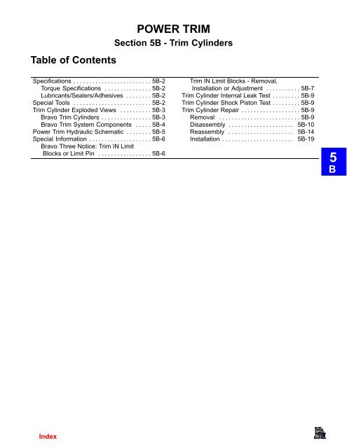
Table of ContentsPOWER TRIMSection 5B - <strong>Trim</strong> <strong>Cylinders</strong>Specifications . . . . . . . . . . . . . . . . . . . . . . . . . 5B-2Torque Specifications . . . . . . . . . . . . . . . 5B-2Lubricants/Sealers/Adhesives . . . . . . . . 5B-2Special Tools . . . . . . . . . . . . . . . . . . . . . . . . . 5B-2<strong>Trim</strong> Cylinder Exploded Views . . . . . . . . . . 5B-3Bravo <strong>Trim</strong> <strong>Cylinders</strong> . . . . . . . . . . . . . . . . 5B-3Bravo <strong>Trim</strong> System Components . . . . . 5B-4Power <strong>Trim</strong> Hydraulic Schematic . . . . . . . . 5B-5Special Information . . . . . . . . . . . . . . . . . . . . 5B-6Bravo Three Notice: <strong>Trim</strong> IN LimitBlocks or Limit Pin . . . . . . . . . . . . . . . . . 5B-6<strong>Trim</strong> IN Limit Blocks - Removal,Installation or Adjustment . . . . . . . . . . . 5B-7<strong>Trim</strong> Cylinder Internal Leak Test . . . . . . . . . 5B-9<strong>Trim</strong> Cylinder Shock Piston Test . . . . . . . . . 5B-9<strong>Trim</strong> Cylinder Repair . . . . . . . . . . . . . . . . . . . 5B-9Removal . . . . . . . . . . . . . . . . . . . . . . . . . . 5B-9Disassembly . . . . . . . . . . . . . . . . . . . . . 5B-10Reassembly . . . . . . . . . . . . . . . . . . . . . 5B-14Installation . . . . . . . . . . . . . . . . . . . . . . . 5B-195B
SpecificationsTorque SpecificationsDESCRIPTIONTORQUElb. in. lb. ft. N·mPiston Rod Bolt 15-20 20-27End Cap 40-50 55-68Anode Screw 30 3.4Lubricants/Sealers/AdhesivesSpecial ToolsNOTE: Prior to reassembly of trim cylinder(s), lubricate all internal parts with QuicksilverPower <strong>Trim</strong> and Steering Fluid or (if not available) 10W-30 or 10W-40 motor oil.DESCRIPTIONPART NUMBERLoctite 27131 92-809820Quicksilver 2-4-C Marine Lubricant with Teflon 92-825407A12Quicksilver Perfect Seal 92-34227--1Quicksilver Power <strong>Trim</strong> and Steering Fluid 92-90100A12DESCRIPTIONPART NUMBERSpanner Nut Wrench 91-821709Large Pin Set 91-811907Medium Pin Set 91-811908Small Pin Set 91-811909
<strong>Trim</strong> Cylinder Exploded ViewsBravo <strong>Trim</strong> <strong>Cylinders</strong>a ab1 - Screws2 - Clamping Plate3 - <strong>Trim</strong> Cylinder4 - O-Ring5 - Floating Piston6 - Bolt7 - Washer8 - Spring Guide9 - Spring10- Spring Guide Washer11- Check Balls12- Shock Piston13- O-Ring14- Small O-Ring15- Continuity Spring16- Small O-Ring17- Large O-Ring18- End Cap19- Rod Scraper20- Washer21- Retaining Ring22- Small O-Ring23- Piston Rod24- Anode25- Star Washer26- Screw27- <strong>Trim</strong>-In Limit Spacers (1/4 in.)28- <strong>Trim</strong>-In Limit Spacers (3/4 in.)29- <strong>Trim</strong>-In Limit Spacers (1-1/4 in.)LUBRICANTS/SEALERS/ADHESIVESLubricate all internal parts with Quicksilver Power <strong>Trim</strong> and Steering Fluid before reassemblingTORQUE SPECIFICATIONa 15-20 lb. ft. (20-27 N·m)b 40-50 lb. ft. (55-68 N·m)73349
Bravo <strong>Trim</strong> System Components735541-”In”/”Down” Hose to <strong>Trim</strong> Pump (Gray)2-”Up”/”Out” Hose to <strong>Trim</strong> Pump (Black)3 - Hose to <strong>Trim</strong> Cylinder4 - Starboard <strong>Trim</strong> Cylinder5 - Port <strong>Trim</strong> Cylinder6 - Starboard <strong>Trim</strong> Cylinder Hose7 - Port <strong>Trim</strong> Cylinder Hose8 - Plate9 - Screw10- Front Pin11- Washer12- Bushing13- Washer14- Nut15- Cap16- Rear Pin17- Washer18- Bushing19- Washer20- Nut21- Cap22- Connector (<strong>Trim</strong> Pump)23- Retainer24- Screw25- Continuity Washer26- <strong>Trim</strong> Cylinder Anode
Power <strong>Trim</strong> Hydraulic Schematic735521 - Shuttle2 - Pump Adaptor3 - Up/Out Pressure Relief Valve4 - Thermal Relief Valve5 - <strong>Trim</strong> Cylinder6 - IN/Down Pressure Relief Valve7 - Up/Out Hose8 - IN/Down Hose9 - Pilot Check Valves
Special InformationBravo Three Notice: <strong>Trim</strong> IN Limit Blocks or Limit PinNOTE: Some earlier Bravo Three models will be equipped with <strong>Trim</strong>-In Limit Blocks, latermodel Bravo One, Two, and Three will have a <strong>Trim</strong>-In Limit Pin. Refer to Sec. 4A for informationon Removal, Installation, or Adjustment of <strong>Trim</strong>-In Limit Blocks.It has been brought to our attention that some boats (predominantly deep-Vee heavy boats)will roll up on their side under certain, specific, operating conditions. The roll can be eitherto port or starboard and may be experienced while moving straight ahead, or while makinga turn. The roll occurs most frequently at or near maximum speed, with the drive unittrimmed at or near full IN. While the boat will not roll completely over, the roll may be sufficientto unseat the operator or passengers, and thereby create an unsafe situation.The roll is caused by “stern lift.” “Stern lift” can be created by excessive drive unit trim “In.”Under these extreme “stern lift”/“bow down” conditions instability can be created which maycause the boat to roll. Weight distribution to the stern can reduce “stern lift” and, in somecircumstances, eliminate the condition. Weight distribution in the bow, port or starboard,may worsen the condition.The <strong>Trim</strong> IN limit devices reduce “stern lift” by preventing the drive unit from reaching thelast few degrees of full trim under. While this device should reduce the rolling tendency, theymay not eliminate the tendency entirely. The need for these trim IN limit blocks or pin, andthe effectiveness of them, can only be determined through boat testing and is ultimately theresponsibility of the boat manufacturer.WARNINGIt is recommended that only qualified personnel remove or adjust the <strong>Trim</strong> IN LimitBlocks or adjust the <strong>Trim</strong>-In Limit Pin. Boat must be water tested after removing oradjusting the device to ensure that the modified trim IN range does not cause theboat to exhibit an undesirable boat handling characteristic if the drive unit istrimmed IN at higher speeds. Increased trim IN range may cause handling problemson some boats which could result in personal injury.IMPORTANT: On Bravo One, Two, and Three Models, the “<strong>Trim</strong>-In Limit Pin” (Ifequipped), must be properly positioned before installing the trim cylinder anchor pinin the following steps.NOTE: When removing the sterndrive unit, make a note of the position of the pin for referencewhen reinstalling the drive unit.
1. If equipped, ensure that the <strong>Trim</strong>-In Limit Pin is positioned as shown for the appropriateBravo model.aa7515775158Bravo One and Two (Positioned Forward)Bravo Three (Positioned Aft)a - <strong>Trim</strong>-In Limit PinIMPORTANT: The position of the <strong>Trim</strong>-In Limit Pin on the Bravo Three sterndrive unitshould only be changed after the boat has been properly tested. Contact the boatmanufacturer if you are not sure of the original position for a particular boat application.<strong>Trim</strong> In Limit Blocks - Removal, Installation or AdjustmentIMPORTANT: Prior to working on trim cylinders, make note of the position of <strong>Trim</strong>-InLimit Blocks, if so equipped.CAUTIONAvoid transom/drive alignment error or interference, or casting damage. Alwaysinstall <strong>Trim</strong> IN Limit Blocks with letters facing up (toward the gimbal ring clevis).1. Disconnect the forward ends of both trim cylinders and remove the cylinders and theirmounting hardware from the anchor pin. DO NOT disconnect the trim hoses.2. Slide the anchor pin out of the gimbal ring. Follow instructions “a”, “b” or “c”:a. To remove blocks: Continue to slide anchor pin out until the trim limit blocks fall offof the pin.
. To Install or adjust blocks to be 3/4 in. (19mm) of trim IN limit: Place block “A”on the port side and block “B” on the starboard side. Always install the blocks withthe letter identifiers facing up (toward the gimbal ring clevis).ab c deidfghj74516a - Anchor Pinb - Flat Washer (Large I.D.)c - Snap Ringd - Rubber Bushings (2)e - <strong>Trim</strong> Cylinderf - Flat Washer (Small I.D.)g - Locknuth - Plastic Capi - Limits The <strong>Trim</strong> IN by 1 in. (25 mm)j - Limits the <strong>Trim</strong> IN By 3/4 In. (19mm)c. To Install or adjust blocks to be 1 in. (25mm) of trim IN limit: Place block “B” onthe port side and block “A” on the starboard side. Always install the blocks with theletter identifiers facing up (toward the gimbal ring clevis).3. Follow appropriate instructions “a” or “b”:a. After removal: Push the anchor pin back through the gimbal ring.b. After installation or adjustment: Push the anchor pin through the <strong>Trim</strong> IN LimitBlocks and on through the gimbal ring.4. Reinstall the trim cylinder(s) and mounting hardware.5. Test the boat to ensure the proper trim IN limit was chosen.NOTE: If these <strong>Trim</strong> IN Limit Blocks do not provide the proper trim IN that is required for yourapplication, the following Quicksilver kits are available (DO NOT use <strong>Trim</strong> IN Limit Blockswith the following kits). The following kits require internal changes to the trim cylinders.23-806445A3 - <strong>Trim</strong> IN Limit Spacer Kit - Limits <strong>Trim</strong> IN by 1/4 or 1/2 in.23-806445A2 -<strong>Trim</strong> IN Limit Spacer Kit - Limits <strong>Trim</strong> IN by 1-1/4 or 1-1/2 in.
<strong>Trim</strong> Cylinder Internal Leak TestRefer to Power <strong>Trim</strong> Pump Sec. 5A.<strong>Trim</strong> Cylinder Shock Piston Test<strong>Trim</strong> Cylinder RepairRefer to Power <strong>Trim</strong> Pump Sec. 5A.Removal1. Disconnect “Up” trim hose from front hole on trim cylinder.2. Disconnect “Down” trim hose from hydraulic connector on gimbal housing. Plug holeswith suitable plug or (P/N 22-38609). Cap hoses.cdbaa-“Up” Hoseb - Front Hole on <strong>Trim</strong> Cylinderc-“Down” Hosed - Hydraulic Connector50389
3. Remove front and rear power trim cylinder mounting hardware.a b c de e f gh71489a - Anchor Pin (1)b - Slots (2)c - Flat Washer (Large I.D.) (2)d - Snap Rings (2)e - Rubber Bushings (4)f - Flat Washer (Small I.D.) (2)g - Locknut (2)h - Plastic Cap (2)cadebcf22029Disassemblya - Rear Anchor Pinb - Large I.D. Washers (Port and Starboard)c - Rubber Bushings (2) (Port and Starboard)d - Small I.D. Washers (Port and Starboard)e - Locknuts (Port and Starboard)f - Plastic Caps (Port and Starboard)CAUTIONEnsure work area is clean before disassembling power trim cylinders. Cylinderparts can be damaged by dirt entering into power trim system.NOTE: Spanner Wrench Tool Part No. 91-821709.71233
CAUTIONDO NOT clamp center section of power trim cylinder during assembly or disassembly.Clamp cylinder on front mounting flange.1. Remove “Down” trim hose from cylinder.a-“Down” <strong>Trim</strong> Hoseb - Clamping Platec - Screwsbca221342. If equipped, remove trim cylinder anodes.ab71966a - Screwsb - <strong>Trim</strong> Cylinder Anodes3. Remove trim cylinder end caps (Use special tool 91-821709).71677
NOTE: Some boat configurations may require tilt-limit spacers to limit the total upward travelof the drive unit. Be sure to make note of the number of spacers used when disassembling.There must be an equal number in each cylinder.4. If Equipped, remove tilt-limit spacers.a7167871679a - Tilt Limit Spacers5. Remove piston rod assembly from cylinder.acba - End Capb - Cylinderc - Piston Rod Assembly221336. Remove floating piston from cylinder and remove O-ring.bcaa - Floating Pistonb - <strong>Trim</strong> Cylinderc - O-ring22131
7. Remove and disassemble shock piston assembly. Be careful not to lose check balls.hcdegfa - Boltb - Flat Washerc - Spring Guided - Springe - Spring Guide Washerf - Check Balls (3)g - Shock Piston Assemblyh - O-ring8. Remove and disassemble end cap.ab22132bdedcafgh22133a - End Capb - Piston Rodc - Large O-ringd - Small O-ring (2)e - Continuity Springf - Rod Scraperg - Plain Washerh - Retaining Ring
9. Remove small O-ring from end of piston rod.ba - Small O-ringb - Piston Roda22132Reassembly10. Clean all parts in solvent. Be sure all parts are dry before reassembly.IMPORTANT: Later model Alpha One drive units use a trim cylinder that is 3/4 in.(19mm) longer, to achieve 6 additional tilt. Earlier model R, MR, and Alpha One, aswell as Bravo drive units, use the shorter trim cylinder. DO NOT attempt to substitutetrim cylinders or damage to drive unit and/or transom assembly could result.<strong>Trim</strong> cylinders can be identified by a casting number on inboard side of trim cylinder.Shorter Cylinder: 98703, 9870498703--1, 98704--1Longer Cylinder: 14034--1, 14035--1CAUTIONEnsure work area and all components are clean before reassembling trim cylinders.Power <strong>Trim</strong> components can become damaged if dirt gets into system.
1. Install small O-ring into end of piston rod.ba - Small O-ringb - End of Piston Roda221322. Install small O-rings and continuity spring into end cap.3. Install rod scraper, plain washer, and retaining ring into end cap.4. Install large O-ring onto outside diameter of end cap.5. Install end cap onto piston rod.e22133c d c i efg h22132c - Small O-ringsd - Continuity Springe - End Capf - Rod Scraperg - Plain Washerh - Retaining Ringi - Large O-ring6. Install large O-ring on shock piston.7. Install check ball, check ball eyelet, spring and spring pin into shock piston.8. Apply Loctite 27131 to threads of bolt being used in the following step.
9. Install shock piston, three check balls, spring guide washer, spring, spring guide, springguide washer and bolt onto piston rod. Torque to 15-20 lb. ft. (20-27 N·m).22133 bgjia - Large O-ringb - Shock Pistonc - Check Balld - check Ball Eyelete - Springf - Spring Ping - Bolth - Check Ballsi - Spring Guide Washerj - Springk - Spring Guidel - Spring Guide Washerfhcbdealk22132NOTE: Before installing floating piston into cylinder, lubricate all internal parts with QuicksilverPower <strong>Trim</strong> and Steering Fluid or SAE 10W-30 or 10W-40 motor oil.10. Apply oil to parts. Install O-ring onto floating piston and insert floating piston into cylinder.cba - O-ringb - Floating Pistonc - Cylindera22132
IMPORTANT: Some boat configurations may require tilt-limit spacers to limit the totalupward travel of the drive unit. Be sure to install the same number of spacers thatwere originally removed. There must be an equal number in each cylinder.11. If required, install tilt-limit spacers.a71678 71679a - Tilt Limit SpacersCAUTIONEnsure work area and all components are clean before reassembling trim cylinders.Power <strong>Trim</strong> components can become damaged if dirt gets into system.NOTE: Before reassembly, lubricate all internal parts with Quicksilver Power <strong>Trim</strong> andSteering Fluid or SAE 10W-30 or 10W-40 motor oil.CAUTIONDO NOT clamp center section of trim cylinder during reassembly. If clamping of cylinderis necessary, clamp cylinder on front mounting flange.CAUTIONUse only 2-4-C Marine Lubricant with Teflon on end cap threads. Other substancesmay act as an insulator and cause poor electrical continuity between cap and cylinderwhich could cause a corrosion problem.12. Apply 2-4-C Marine Lubricant with Teflon to end cap threads and install piston rod assemblyinto cylinder.abca - End Capb - Piston Rodc - Cylinder22133
13. Using Spanner Wrench Tool P/N 91-821709, torque end cap 40-50 lb. ft. (55-68 N·m).aa - Spanner Wrench14. If equipped, install trim cylinder anodes.71677aba - Screws (2 Each)b - Anode (Each <strong>Trim</strong> Cylinder)15. Position trim cylinder rear connecting ends as shown.71966abca - Port <strong>Trim</strong> Cylinderb - Starboard <strong>Trim</strong> Cylinderc - Connecting Ends (Angled as Shown)22135
16. Install “Down” trim hose.aa-“Down” <strong>Trim</strong> Hoseb - Clamping Platec - Screwsbc22130Installation17. Check painted areas of trim cylinders for scratches that expose metal, paint if necessary.CAUTIONUse water and soap solution to aid in installing rubber bushings. The use of a petroleumbased product (oil or grease) can deteriorate rubber.NOTE: Refer to “Special Information” at the front of this section before reinstalling trim cylinders.NOTE: The bushings on Later Bravo drive units are made from a different type of material.The later style is harder. The bushing can also be identified by a small indentation on theoutside face of the bushing. Do not mix the earlier style rubber bushings with the later style.caa - Earlier Style Bushingb - Later Style Bushingc - Indentation on Later styleb752711. Install trim cylinder forward mounting hardware as shown.2. Coat anchor pin threads with 2-4-C Marine Lubricant with Teflon (to prevent threadsfrom galling).
3. Hand thread locknuts onto pin. DO NOT tighten at this time.a b c d e e f gha - Anchor Pin (1)b - Slots (2)c - Flat Washer (Large I.D.) (2)d - Snap Rings (2)e - Rubber Bushings (4)f - Washers (Small I.D.) (2)g - Locknut (2)h - Plastic Cap (2)71489IMPORTANT: On Bravo One, Two, and Three Models, the “<strong>Trim</strong>-In Limit Pin” (Ifequipped), must be properly positioned before installing the trim cylinder anchor pinin the following steps.NOTE: Ensure that the <strong>Trim</strong>-In Limit Pin is reinstalled in the same position that is was in priorto removal of the sterndrive unit. If you are not sure of it’s original position, contact the boatmanufacturer for their recommendation. Refer to Special Information at the front of this sectionbefore reinstalling the <strong>Trim</strong>-In Limit Pin.4. If equipped, ensure that the <strong>Trim</strong>-In -Limit Pin is positioned as shown for the appropriateBravo model.aa7515775158Bravo One and Two (Positioned Forward)Bravo Three (Positioned Aft)a - <strong>Trim</strong>-In Limit PinIMPORTANT: The position of the <strong>Trim</strong>-In Limit Pin on the Bravo Three sterndrive unitshould only be changed after the boat has been properly tested. Contact the boatmanufacturer if you are not sure of the original position for a particular boat application.
5. Install trim cylinder aft mounting hardware as shown.6. Coat anchor pin threads with 2-4-C Marine Lubricant with Teflon to prevent threads fromgalling.7. Hand thread locknuts onto anchor pin. Install plastic caps.aebccdf22029a - Aft Anchor Pin (Shorter)b - Washers (2) - Large I.D.c - Rubber Bushingsd - Washers (2) - Small I.D.e - Locknuts (2)f - Plastic Caps (2)CAUTIONAll 4 anchor pin locknuts must be tightened as described following or damage tosterndrive unit may result from drive unit moving too far inward.8. Tighten 4 anchor pin locknuts until nuts and washers bottom out against anchor pinshoulder.9. Reconnect trim hoses after air bleeding power trim cylinders and hoses following proceduresoutlined in Section 5A.
THIS PAGE IS INTENTIONALLY BLANK