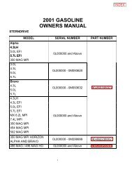
CORROSION PROTECTION
CORROSION PROTECTION
CORROSION PROTECTION

Create successful ePaper yourself
Turn your PDF publications into a flip-book with our unique Google optimized e-Paper software.
SERVICE MANUAL NUMBER 11<br />
Table of Contents<br />
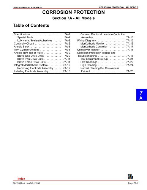
<strong>CORROSION</strong> <strong>PROTECTION</strong><br />
Section 7A - All Models<br />
<strong>CORROSION</strong> <strong>PROTECTION</strong> - ALL MODELS<br />
Specifications . . . . . . . . . . . . . . . . . . . . . . . 7A-2<br />
Special Tools . . . . . . . . . . . . . . . . . . . . . 7A-2<br />
Lubricants/Sealers/Adhesives . . . . . . 7A-2<br />
Continuity Circuit . . . . . . . . . . . . . . . . . . . . 7A-2<br />
Anodic Block . . . . . . . . . . . . . . . . . . . . . . . 7A-5<br />
Trim Cylinder Anodes . . . . . . . . . . . . . . . . 7A-8<br />
Anodic Trim Tab or Plate . . . . . . . . . . . . . 7A-9<br />
Bravo One Drive Units . . . . . . . . . . . . 7A-9<br />
Bravo Two Drive Units . . . . . . . . . . . . . 7A-11<br />
Bravo Three Drive Units . . . . . . . . . . . 7A-11<br />
Integral MerCathode System . . . . . . . . . . 7A-12<br />
Removing Electrode Assembly . . . . . 7A-12<br />
Installing Electrode Assembly . . . . . . . . . 7A-13<br />
Connect Electrical Leads to Controller<br />
Assembly . . . . . . . . . . . . . . . . . . . . . . . 7A-15<br />
Wiring Diagrams . . . . . . . . . . . . . . . . . . . . 7A-16<br />
MerCathode Monitor . . . . . . . . . . . . . . 7A-16<br />
MerCathode Controller . . . . . . . . . . . . 7A-17<br />
Quicksilver Isolator . . . . . . . . . . . . . . . . . . 7A-18<br />
Corrosion Protection Testing and<br />
Troubleshooting . . . . . . . . . . . . . . . . . . . . 7A-18<br />
Test Equipment Set-Up . . . . . . . . . . . . 7A-21<br />
Low Readings . . . . . . . . . . . . . . . . . . . . 7A-22<br />
High Reading . . . . . . . . . . . . . . . . . . . . 7A-24<br />
Normal Reading But Corrosion is<br />
Evident . . . . . . . . . . . . . . . . . . . . . . . . . 7A-25<br />
7<br />
A<br />
90-17431--4 MARCH 1998 Page 7A-1
<strong>CORROSION</strong> <strong>PROTECTION</strong> - ALL MODELS SERVICE MANUAL NUMBER 11<br />
Specifications<br />
Special Tools<br />
DESCRIPTION<br />
MerCathode Reference Electrode Test<br />
PART NUMBER<br />
76675A1<br />
Quicksilver VOA Meter* 91-62562A1<br />
*If you do not already have this meter, use a digital multi-meter (such as a Radio Shack<br />
22-191). DO NOT use a standard analog (Needle-Type) Meter as inaccurate readings will<br />
result.<br />
IMPORTANT: Quicksilver Volt/Ohm Meter 91-93572 and Multi-Meter DVA/Tester<br />
91-99750 are no longer recommended for testing corrosion protection.<br />
Lubricants/Sealers/Adhesives<br />
Continuity Circuit<br />
DESCRIPTION<br />
PART NUMBER<br />
Quicksilver Liquid Neoprene 92-25711-2<br />
Transom assembly and sterndrive unit are equipped with ground circuit wires to ensure<br />
good electrical continuity between engine, transom assembly, and sterndrive components.<br />
Good continuity is essential for the zinc trim tab and MerCathode System to function most<br />
effectively.<br />
Inspect the following ground circuit components, at intervals (Section 1B), for loose connections,<br />
broken or fraying wires.<br />
a - Steering Lever Ground Wire<br />
a<br />
22028<br />
Page 7A-2<br />
90-17431--4 MARCH 1998
SERVICE MANUAL NUMBER 11<br />
<strong>CORROSION</strong> <strong>PROTECTION</strong> - ALL MODELS<br />
a<br />
b<br />
22650 22754<br />
a - Inner Transom Plate to Gimbal Housing Ground Wire<br />
b - Driveshaft Housing to Gear Housing Ground Plate (Inside Trim Tab Cavity)<br />
a<br />
a - Gimbal Housing to Gimbal Ring Ground Wire<br />
22230<br />
a<br />
b<br />
a<br />
b<br />
c<br />
c<br />
22028 50242<br />
Gasoline Models<br />
Diesel Models<br />
a - Flywheel Housing Grounding Stud<br />
b - Ground Wire<br />
c - Inner Transom Plate Grounding Screw - DO NOT Ground ANY Accessory at this connection<br />
90-17431--4 MARCH 1998 Page 7A-3
<strong>CORROSION</strong> <strong>PROTECTION</strong> - ALL MODELS SERVICE MANUAL NUMBER 11<br />
d<br />
22755<br />
d - Gimbal Ring to Bell Housing Ground Wire<br />
e - Drive Unit to Bell Housing Ground Plate<br />
f<br />
e<br />
22031<br />
70575<br />
f - Driveshaft Housing to Gear Housing Anodic Plate<br />
g - Hydraulic Connector Block to Gimbal Housing Ground Washer<br />
g<br />
22230<br />
h<br />
h<br />
70759<br />
h - Anodic Block to Hydraulic Manifold and Ground Washers (Beneath Screws).<br />
i<br />
j<br />
i - U-joint Bellows Ground Clip<br />
j - Exhaust Bellows Ground Clips<br />
50383 22079<br />
Page 7A-4<br />
90-17431--4 MARCH 1998
SERVICE MANUAL NUMBER 11<br />
Anodic Block<br />
<strong>CORROSION</strong> <strong>PROTECTION</strong> - ALL MODELS<br />
CAUTION<br />
DO NOT paint new anodic block as this will render it ineffective as a galvanic corrosion<br />
inhibitor.<br />
1. Remove screws, ground washers and gasket from anodic block. Remove anodic block<br />
to hydraulic manifold gasket and discard.<br />
a<br />
e<br />
d<br />
c<br />
b<br />
70763<br />
70759<br />
Earlier Style Anodic Block<br />
a - Anodic Block<br />
b - Screws<br />
c - Continuity Washers<br />
d - Gasket<br />
e - Seal<br />
a<br />
e<br />
d<br />
c<br />
73315<br />
b<br />
Later Style Anodic Block<br />
a - Anodic Block<br />
b - Screw<br />
c - Continuity Washer<br />
d - Gasket<br />
e - Seal<br />
73892<br />
90-17431--4 MARCH 1998 Page 7A-5
<strong>CORROSION</strong> <strong>PROTECTION</strong> - ALL MODELS SERVICE MANUAL NUMBER 11<br />
2. Check condition of hydraulic manifold and clean any debris from threaded holes.<br />
a<br />
a - Screw Holes<br />
b - Hydraulic Manifold<br />
70748<br />
3. Examine rubber seal inside of hydraulic manifold block for signs of leakage or wear. Replace<br />
if necessary.<br />
b<br />
a<br />
b<br />
5070773<br />
a - Hydraulic Manifold<br />
b - Rubber Seal<br />
70748<br />
4. If rubber seal needs replacement, push old seal out of hydraulic manifold and install new<br />
seal as shown.<br />
a<br />
b<br />
70774<br />
a - Hydraulic Manifold<br />
b - Rubber Seal<br />
Page 7A-6<br />
90-17431--4 MARCH 1998
SERVICE MANUAL NUMBER 11<br />
5. Install screws and washers into block as shown.<br />
<strong>CORROSION</strong> <strong>PROTECTION</strong> - ALL MODELS<br />
b<br />
c<br />
a<br />
a - Screws (2)<br />
b - Anodic Block<br />
c - Continuity Washers (2)<br />
70760<br />
CAUTION<br />
To be effective, new anodic block MUST make good continuity contact with gimbal<br />
housing.<br />
6. Be sure new gasket is in proper position between anodic block and hydraulic manifold.<br />
Apply Quicksilver Perfect Seal (P/N 92-34227-1) to threads of screw once they are<br />
through block.<br />
c<br />
b<br />
a<br />
70772<br />
a - Screws (2)<br />
b - Anodic Block<br />
c - Gasket<br />
7. Snug both screws evenly into hydraulic manifold, then torque to 80-120 lb. in. (9-14<br />
Nm).<br />
b<br />
a<br />
70759<br />
a - Screws and Washers<br />
b - Anodic Block<br />
90-17431--4 MARCH 1998 Page 7A-7
<strong>CORROSION</strong> <strong>PROTECTION</strong> - ALL MODELS SERVICE MANUAL NUMBER 11<br />
Trim Cylinder Anodes<br />
CAUTION<br />
DO NOT paint new trim cylinder anodes, as this will render them ineffective as a galvanic<br />
corrosion inhibitor.<br />
1. Remove screws that secure anodes to trim cylinders. Remove anodes.<br />
a<br />
a - Screws<br />
b - Trim Cylinder Anodes<br />
b<br />
71966<br />
2. Scrape mounting surface on cylinder end-cap down to bare metal.<br />
3. Install new anodes and tighten securely.<br />
Page 7A-8<br />
90-17431--4 MARCH 1998
SERVICE MANUAL NUMBER 11<br />
Anodic Trim Tab or Plate<br />
<strong>CORROSION</strong> <strong>PROTECTION</strong> - ALL MODELS<br />
NOTE: Later models are equipped with an anodic plate instead of trim tab. Replacement<br />
procedure is the same.<br />
a - Trim Tab<br />
b - Anodic Plate<br />
Bravo One Drive Units<br />
a<br />
b<br />
CAUTION<br />
75251<br />
DO NOT paint new trim tab (or anodic plate), as this will render it ineffective as a<br />
galvanic corrosion inhibitor.<br />
1. Remove plug from driveshaft housing to gain access to attaching screw.<br />
a<br />
22093<br />
a - Plug<br />
2. Use a 1/2 in. standard socket and extension, loosen screw, and remove trim tab (or<br />
anodic plate).<br />
d<br />
c<br />
b<br />
e<br />
a - Trim Tab (Or Anodic Plate, Depending Upon Model)<br />
b - Plug - (Removed)<br />
c - 1/2 in. Socket<br />
d - Extension<br />
e - Screw<br />
a<br />
22258<br />
90-17431--4 MARCH 1998 Page 7A-9
<strong>CORROSION</strong> <strong>PROTECTION</strong> - ALL MODELS SERVICE MANUAL NUMBER 11<br />
CAUTION<br />
To be effective, new trim tab (or anodic plate) MUST make good electrical contact<br />
with gear housing.<br />
3. Scrape trim tab (or anodic plate) mounting surface on gear housing down to bare metal.<br />
4. Install trim tab and align straight back. Torque screw to 25-35 lb. ft. (34-47 Nm).<br />
d<br />
c<br />
b<br />
e<br />
a - Trim Tab (Or Anodic Plate, Depending Upon Model)<br />
b - Plug - (Removed)<br />
c - 1/2 in. Socket<br />
d - Extension<br />
e - Screw<br />
a<br />
22258<br />
5. Reinstall plug in driveshaft housing.<br />
a<br />
22093<br />
a - Plug<br />
Page 7A-10<br />
90-17431--4 MARCH 1998
SERVICE MANUAL NUMBER 11<br />
Bravo Two Drive Units<br />
<strong>CORROSION</strong> <strong>PROTECTION</strong> - ALL MODELS<br />
1. Use a 1/2 in. standard socket to loosen screw and remove trim tab.<br />
2. Scrape trim tab mounting surface down to bare metal to insure continuity.<br />
3. Install trim tab and align straight back. Torque screw to 25-35 lb. ft. (34-47 Nm).<br />
b<br />
a<br />
Bravo Three Drive Units<br />
a - Screw [Torque to 25-35 lb. ft. (34-47 Nm)]<br />
b - Trim Tab (Position Straight Back)<br />
50323<br />
NOTE: Earlier Bravo Three drive units were equipped with two anodic plates. The rear<br />
anode is attached with a bolt from the bottom side of the splash plate.<br />
b<br />
a<br />
a - Anodic Plates<br />
b - Screw (Attaches From Bottom Side)<br />
1. Remove plastic cap to gain access to the anode (front) attaching bolt.<br />
a<br />
72029<br />
b<br />
a - Plastic Cap (Removed)<br />
b - Bolt<br />
71804<br />
2. Scrape the mounting surface on gear housing down to bare metal to insure continuity.<br />
3. Install new anode(s). Torque to 23 lb. ft. (32 Nm).<br />
4. Reinstall plastic cap.<br />
90-17431--4 MARCH 1998 Page 7A-11
<strong>CORROSION</strong> <strong>PROTECTION</strong> - ALL MODELS SERVICE MANUAL NUMBER 11<br />
Integral MerCathode System<br />
Removing Electrode Assembly<br />
1. Disconnect electrode assembly wires from MerCathode Controller.<br />
e<br />
a<br />
a - Electrode Assembly Wire (Orange)<br />
b - Electrode Assembly Wire (Brown)<br />
c - Earlier Models - Trim Position Sender Wire (Black)<br />
d - Earlier Models - Trim Position Sender Wire (Black)<br />
e - Earlier Models - Wire to Trim Position Gauge (Brown/White)<br />
c<br />
b<br />
d<br />
22032<br />
2. Remove two screws, flat washers and lock washers; then remove electrode assembly.<br />
e<br />
d<br />
b<br />
c<br />
a<br />
70771<br />
a - Electrode Assembly<br />
b - Screw (2)<br />
c - Flat Washer (2)<br />
d - Lock Washer (2)<br />
e - Hydraulic Connector Block<br />
Page 7A-12<br />
90-17431--4 MARCH 1998
SERVICE MANUAL NUMBER 11<br />
Installing Electrode Assembly<br />
<strong>CORROSION</strong> <strong>PROTECTION</strong> - ALL MODELS<br />
CAUTION<br />
O-ring MUST BE properly seated in groove of electrode assembly or water leakage<br />
into boat will result.<br />
1. Earlier Model Electrodes: Install the O-ring over the orange and brown wires from the<br />
electrode assembly. Seat the O-ring in the groove. DO NOT use any type of sealer on<br />
the O-ring.<br />
b<br />
a<br />
a - O-ring Groove<br />
b - O-ring<br />
70756<br />
2. Later Model Electrodes: Later model electrodes have a factory installed rubber grommet<br />
and DO NOT require an O-ring.<br />
a - Electrode<br />
b - Rubber Grommet<br />
a<br />
b<br />
71862<br />
90-17431--4 MARCH 1998 Page 7A-13
<strong>CORROSION</strong> <strong>PROTECTION</strong> - ALL MODELS SERVICE MANUAL NUMBER 11<br />
3. Form a 2 ft. (610mm) long piece of approximately .032 in. diameter wire to the dimensions<br />
shown.<br />
c<br />
d<br />
b<br />
a<br />
a - 2 ft. (610mm) OF APPROXIMATELY .032 in. (.8mm) DIA. WIRE<br />
b - 5 in. (123 mm)<br />
c-45 Angle<br />
d - 1/2 in. (13 mm)<br />
74106<br />
4. Insert 45 angle end of wire through center hole in hydraulic connector block.<br />
5. Guide wire through hole until wire protrudes through cavity on the bottom of exhaust<br />
pipe.<br />
a<br />
a<br />
22235<br />
a - Wire<br />
6. Secure ring terminals to tracer wire.<br />
7. Guide leads through center hole in connector block.<br />
IMPORTANT: Orange lead is approximately 6 in. (150mm) longer than the brown lead.<br />
Page 7A-14<br />
90-17431--4 MARCH 1998
SERVICE MANUAL NUMBER 11<br />
8. Pull leads ALL the way into the boat.<br />
<strong>CORROSION</strong> <strong>PROTECTION</strong> - ALL MODELS<br />
a<br />
b<br />
22234<br />
a - Wire<br />
b - Leads<br />
CAUTION<br />
DO NOT paint sacrificial anodes or MerCathode System electrode assembly, as this<br />
will render them ineffective as galvanic corrosion inhibitors.<br />
9. Position and secure electrode assembly to gimbal housing using two 1-3/8 in. (35mm)<br />
long screws, flat washers and lockwashers. Torque to 20-30 lb. in. (2.2-3.3 Nm). DO<br />
NOT OVERTIGHTEN.<br />
e<br />
d<br />
b<br />
c<br />
a<br />
70771<br />
a - Electrode Assembly<br />
b - Screw (2)<br />
c - Flat Washer (2)<br />
d - Lock Washer (2)<br />
e - Hydraulic Connector Block<br />
Connect Electrical Leads to Controller Assembly<br />
NOTE: If black (ground) wire is not available at terminal block or from wire harness, install<br />
a separate lead between controller negative (–) terminal and negative (–) battery cable attaching<br />
point on engine.<br />
1. Connect electrical leads to controller assembly, securely. (See applicable Wiring Diagrams,<br />
following.)<br />
2. Apply a thin coat of Quicksilver Liquid Neoprene (92-25711) to ALL electrical connections.<br />
90-17431--4 MARCH 1998 Page 7A-15
<strong>CORROSION</strong> <strong>PROTECTION</strong> - ALL MODELS SERVICE MANUAL NUMBER 11<br />
Wiring Diagrams<br />
MerCathode Monitor<br />
e<br />
a<br />
d<br />
b<br />
c<br />
a - Ground to a Suitable Ground on the Instrument Panel<br />
b - Screw, Nut and Sleeve<br />
c - Electrode<br />
d - 20 Amp Fuse<br />
e - Controller<br />
74251<br />
Page 7A-16<br />
90-17431--4 MARCH 1998
SERVICE MANUAL NUMBER 11<br />
MerCathode Controller<br />
<strong>CORROSION</strong> <strong>PROTECTION</strong> - ALL MODELS<br />
a<br />
b<br />
c<br />
73596<br />
a - Controller<br />
b - 20 Amp Fuse<br />
c - Electrode<br />
90-17431--4 MARCH 1998 Page 7A-17
<strong>CORROSION</strong> <strong>PROTECTION</strong> - ALL MODELS SERVICE MANUAL NUMBER 11<br />
Quicksilver Isolator<br />
Boats, which are connected to A.C. shore power require additional protection, to prevent<br />
destructive low voltage galvanic currents from passing thru the shore power ground wire.<br />
A Quicksilver Isolator (7664A3) can be installed to block the passage of these currents,<br />
while still providing a path to ground for dangerous fault (shock) currents.<br />
CAUTION<br />
If A.C. shore power is not isolated from boat ground, the MerCathode System and<br />
sacrificial anodes may be unable to handle the increased galvanic corrosion potential.<br />
a<br />
a - Quicksilver Isolator<br />
Corrosion Protection Testing and Troubleshooting<br />
70972<br />
NOTE: The following corrosion protection test supersedes all previously issued tests. This<br />
test can be used on applications with or without a MerCathode System.<br />
Use the following test to determine if drive unit is being afforded adequate corrosion protection,<br />
or if additional corrosion protection is required. If the unit is equipped with a MerCathode<br />
System, it is recommended that this test be performed at least once each year, where<br />
the boat is moored, to ensure that the system is functioning properly.<br />
Test requires the us of MerCathode Reference Electrode Test 76675A1, and Quicksilver<br />
VOA meter 91-62562A1. This meter is no longer available from Mercury Marine. If you do<br />
not already have this meter, a digital multi-meter (such as a Radio Shack 22-191) must be<br />
used. A STANDARD ANALOG (Needle-Type) METER CANNOT BE USED, AS AN INAC-<br />
CURATE READING WILL RESULT.<br />
IMPORTANT: Quicksilver Volt/Ohm Meter 91-93572, and Multi-Meter DVA/Tester<br />
91-99750, are no longer recommended for testing corrosion protection.<br />
Page 7A-18<br />
90-17431--4 MARCH 1998
SERVICE MANUAL NUMBER 11<br />
<strong>CORROSION</strong> <strong>PROTECTION</strong> - ALL MODELS<br />
The MerCathode Reference Electrode Tester 76675A1 is equipped with a special jack (containing<br />
a resistor to provide the proper scale reading when used with Quicksilver VOA Meter<br />
91-6256A1. Previously, we stated that this plug could be removed to allow tester to be used<br />
with other analog type meters. Further testing has revealed that this could result in inaccurate<br />
readings and, therefore, we no longer recommend the removal of this plug, and the<br />
use of other analog meters. Resistor jack can be left in place when using digital meters.<br />
a<br />
22465<br />
Quicksilver VOA Meter 91-62562A1 and MerCathode Reference Tester 76675A1<br />
a - Special Resistor Jack<br />
NOTE: Set-up test equipment as shown on page 7A-21.<br />
IMPORTANT: Be sure to observe the following when performing test:<br />
If equipped with MerCathode System, ensure battery is fully charged (12.6 Volts<br />
or above).<br />
New boats just placed in service usually will produce a reading higher than normal.<br />
This is due to the drive unit being protected by a good finish and new sacrificial<br />
anodes. To obtain an accurate diagnosis, the test should be performed after<br />
the boat has been in service at least one or two weeks. This will give the paint a<br />
chance to “soak” and Minor abrasions and scratches will have appeared, which<br />
will result in al more accurate reading.<br />
Boats should be moored, without being operated, for at least 8 hours before performing<br />
tests. This is necessary to allow the MerCathode System and/or sacrificial<br />
anodes to polarize the surrounding water. Be careful not to rock the boat excessively<br />
while boarding to perform a test as this will alter the test reading.<br />
1. Plug negative meter lead into negative (–) receptacle of meter. Connect other end of<br />
lead to negative (–) battery terminal or other convenient engine ground.<br />
2. Plug Reference Electrode Tester lead into positive (+) receptacle of meter.<br />
3. If using Quicksilver VOA Meter 91-62562A1, set meter on “AUX TEST” position. If using<br />
a digital meter, set meter on scale required to read 0-2000 millivolts (0-2 volts).<br />
90-17431--4 MARCH 1998 Page 7A-19
<strong>CORROSION</strong> <strong>PROTECTION</strong> - ALL MODELS SERVICE MANUAL NUMBER 11<br />
4. Immerse Electrode Tester in the water within 6 in. (150mm) of aft end of drive unit.<br />
IMPORTANT: There will be different voltage readings depending on the type of Mer-<br />
Cathode System you are testing.<br />
Electrode Mounted on Bottom of Transom Assembly<br />
71894<br />
Electrodes Mounted on Boat Transom<br />
5. The following readings indicate that sterndrive is adequately protected:<br />
a. MODELS WITH ELECTRODES MOUNTED ON BOAT TRANSOM<br />
Fresh Water Areas -<br />
7.5 - 10.5 millivolts with Quicksilver<br />
VOA Meter<br />
750 - 1050 Millivolts with Digital Meter<br />
71895<br />
Salt, Polluted or Mineral Laden Water Areas:<br />
8.8 - 10.5 millivolts with Quicksilver<br />
VOA Meter<br />
880 - 1050 Millivolts with Digital Meter<br />
b. MODELS WITH ELECTRODE MOUNTED ON BOTTOM OF TRANSOM ASSEMBLY<br />
Fresh Water Areas -<br />
6.2 - 11.8 Millivolts with Quicksilver<br />
VOA Meter<br />
620 - 1180 Millivolts with Digital Meter<br />
Salt, Polluted or Mineral Laden Water Areas:<br />
7.5 - 11.8 Millivolts with Quicksilver<br />
VOA Meter<br />
750 - 1180 Millivolts with Digital Meter<br />
6. If the reading is not within specified limits, or if reading is within specifications, but there<br />
is evidence of corrosion on sterndrive, refer to the appropriate troubleshooting chart, following<br />
to aid in diagnosis.<br />
Page 7A-20<br />
90-17431--4 MARCH 1998
SERVICE MANUAL NUMBER 11<br />
Test Equipment Set-Up<br />
<strong>CORROSION</strong> <strong>PROTECTION</strong> - ALL MODELS<br />
6 IN. (915 MM)<br />
(MAX.)<br />
70755<br />
90-17431--4 MARCH 1998 Page 7A-21
<strong>CORROSION</strong> <strong>PROTECTION</strong> - ALL MODELS SERVICE MANUAL NUMBER 11<br />
Low Readings<br />
Cause<br />
Remedy<br />
1. Loss of continuity between drive unit<br />
components and negative (-) battery terminal.<br />
2. Shore power green safety grounding<br />
lead not isolated from the power package<br />
ground (on boats equipped with<br />
shore power).<br />
3. Underwater metal parts on the drive unit<br />
and/or boat are unpainted or the paint is<br />
in poor condition. The boat has more exposed<br />
metal than the anodes and/or<br />
MerCathode system can protect.<br />
4. Anodes painted.<br />
5. The anodes are improperly grounded or<br />
inactive.<br />
6. Anodes consumed (no longer protect).<br />
7. Drive unit and/or boat bottom painted<br />
with anti-fouling pant containing copper<br />
or tin.<br />
8. MerCathode reference electrode or<br />
anode painted.<br />
9. Anodic heads used instead of plastic<br />
caps.<br />
10. No power to MerCathode controller.<br />
11. Poor connection between reference<br />
electrode lead (brown) or anode lead<br />
(orange) and MerCathode controller.<br />
1. Ensure that continuity devices are not<br />
missing or damaged and that connections<br />
are clean and tight.<br />
2. Disconnect shore power and notice if<br />
reading increases. If so, install a Quicksilver<br />
Isolator 76664A3 or an isolation<br />
transformer.<br />
3. Prime and paint underwater metal parts.<br />
This will reduce the load on the anodes<br />
and/or MerCathode system.<br />
4. Remove paint or replace anodes.<br />
5. Clean anode mounting surface or<br />
replace anodes if they have oxidized.<br />
6. Replace anodes if eroded 50% or more.<br />
7. Avoid any electrical interconnection<br />
between the MerCruiser product, Anodic<br />
Blocks, or MerCathode system and<br />
the paint by allowing a minimum of 1-1/2<br />
in. (40 mm) of UNPAINTED area around<br />
these items on the transom of the boat.<br />
8. Remove paint.<br />
9. Reinstall the plastic caps.<br />
10. Connect the positive (+) volt meter lead<br />
(set on 0-20 volt scale) to the positive<br />
(+) controller terminal and the negative<br />
(–) volt meter lead to the negative (–)<br />
terminal. The meter should indicate battery<br />
voltage. Check for a blown fuse (if<br />
so equipped) on the starboard MerCathode<br />
system. Clean the connection or<br />
repair wiring as required.<br />
11. Clean and/or tighten the connection.<br />
Repair the wiring.<br />
Page 7A-22<br />
90-17431--4 MARCH 1998
SERVICE MANUAL NUMBER 11<br />
Low Readings (continued)<br />
Cause<br />
12. Faulty MerCathode reference electrode.<br />
13. Faulty MerCathode Controller.<br />
14. Additional corrosion protection<br />
required. Boats which are equipped with<br />
a sizable amount of underwater metal<br />
(stainless steel prop, after planes, etc.),<br />
or that are moored in an area with warm<br />
or rapid flowing water, may require additional<br />
protection.<br />
<strong>CORROSION</strong> <strong>PROTECTION</strong> - ALL MODELS<br />
Remedy<br />
12. Disconnect the reference electrode<br />
lead(brown) from the controller “R” terminal.<br />
Connect the lead to the positive<br />
(+) terminal of a digital multimeter (set<br />
on 0-2000 millivolt scale). Connect the<br />
negative (–) meter lead to the negative<br />
(–) battery terminal. Note the meter<br />
reading; then repeat the test using a<br />
MerCathode Reference Electrode Tester<br />
76675A1. You should obtain the<br />
same reading in both cases. If not, replace<br />
the reference electrode.<br />
13. With anode and reference electrode<br />
leads connected to the controller, connect<br />
the jumper wire between “R” and<br />
negative (-) terminals on the controller.<br />
Connect the positive (+) lead of the volt<br />
meter (set on 0-20 scale) to “A” terminal<br />
on the controller. Connect the negative<br />
(-) meter lead to the negative (-) controller<br />
terminal. Reading should be as follows:<br />
Freshwater Areas -<br />
Electrodes Mounted on boat transom:<br />
7.5 - 10.5 Millivolts<br />
Electrode mounted on bottom transom<br />
assembly: 6.2 - 11.8 Millivolts<br />
Saltwater Areas -<br />
Electrodes mounted on boat transom:<br />
8.8 - 10.5 Millivolts<br />
Electrode mounted on bottom of transom<br />
assembly: 7.5 - 11.8 Millivolts<br />
If the reading is low, replace the controller.<br />
14. Install additional anodes or MerCathode<br />
system 88334A2. If the unit is already<br />
equipped with a MerCathode system, a<br />
second system may be required.<br />
90-17431--4 MARCH 1998 Page 7A-23
<strong>CORROSION</strong> <strong>PROTECTION</strong> - ALL MODELS SERVICE MANUAL NUMBER 11<br />
High Reading<br />
Cause<br />
1. Stray current corrosion. If an electrical<br />
current flowing along a metal conductor<br />
leaves the metal for a water path, it will<br />
cause ionization of the metal, and an<br />
area of rapid corrosion.<br />
2. Poor connection between MerCathode<br />
reference electrode lead (brown) and<br />
“R” terminal on controller.<br />
3. Faulty MerCathode reference electrode.<br />
4. Faulty MerCathode controller.<br />
Remedy<br />
1. Observe the reading while disconnecting<br />
the electrical components one at a<br />
time until you eliminate the high reading.<br />
Correct the course of stray current.<br />
2. Clean and /or tighten connection. Repair<br />
wiring as required.<br />
3. Disconnect the reference electrode lead<br />
(brown) from “R” terminal on the controller.<br />
Connect the lead to the positive (+)<br />
terminal of a digital multi-meter (set on<br />
0-2000 millivolt scale). Connect the negative<br />
(–) meter lead to the negative (–)<br />
battery terminal. Note the meter reading;<br />
then, repeat the test using MerCathode<br />
Reference Electrode Tester<br />
76675A1. Both tools should produce the<br />
same reading. If not, replace the reference<br />
electrode.<br />
4. Replace the controller.<br />
Page 7A-24<br />
90-17431--4 MARCH 1998
SERVICE MANUAL NUMBER 11<br />
Normal Reading But Corrosion is Evident<br />
<strong>CORROSION</strong> <strong>PROTECTION</strong> - ALL MODELS<br />
<strong>CORROSION</strong> ON THE ENTIRE DRIVE UNIT<br />
Cause<br />
The drive unit is raised so fare that<br />
the sacrificial anodic trim tab is out of<br />
the water.<br />
Remedy<br />
Leave the drive unit in the “In”/“Down”<br />
position when the boat is moored to<br />
ensure the trim tab is in the water,<br />
providing protection.<br />
<strong>CORROSION</strong> PROBLEM DEVELOPED AFTER REFINISHING THE DRIVE UNIT<br />
Cause<br />
A steel wire brush was used to clean<br />
the aluminum casting. Steel particles<br />
became en-trapped and set up a<br />
small galvanic cell.<br />
Remedy<br />
Use only a nylon or bristle brush.<br />
PAINT BLISTERING ON DRIVE UNIT<br />
Cause<br />
Battery charger, which uses 110 volt<br />
shore power, improperly connected to<br />
the battery.<br />
Remedy<br />
Ensure the charger is connected<br />
correctly.<br />
TRIM CYLINDER CORRODING<br />
Cause<br />
Continuity lost between trim cylinder<br />
and drive unit.<br />
Remedy<br />
Install proper continuity devices.<br />
ONLY ONE OR TWO COMPONENTS CORRODING (BELL HOUSING, GIMBAL RING, ETC.)<br />
Cause<br />
Continuity lost between drive unit and<br />
components.<br />
Remedy<br />
If not already done, install Continuity<br />
Circuit Kit 99940A1.<br />
<strong>CORROSION</strong> IN THE EXHAUST OUTLET AREA<br />
Cause<br />
Exhaust gas deposits accumulating<br />
on the drive exterior can result in paint<br />
blistering and corrosion.<br />
Remedy<br />
Remove deposits with marine or<br />
automotive wax.<br />
<strong>CORROSION</strong> OCCURS AFTER THE UNIT IS REMOVED FROM THE WATER<br />
Cause<br />
Salt crystals remaining on the surface<br />
of the drive components combine with<br />
high humidity to cause electrolyte<br />
formation, which results in corrosion.<br />
Remedy<br />
Wash drive exterior and flush drive<br />
interior with fresh water.<br />
90-17431--4 MARCH 1998 Page 7A-25
<strong>CORROSION</strong> <strong>PROTECTION</strong> - ALL MODELS SERVICE MANUAL NUMBER 11<br />
<strong>CORROSION</strong> BETWEEN SURFACES<br />
Cause<br />
Salt buildup between surfaces.<br />
Remedy<br />
Protect mating parts with Quicksilver<br />
Special Lubricant 101 (92-13872A1),<br />
Quicksilver 2-4-C Marine Lubricant<br />
(92-825407A2), or Perfect Seal<br />
(92-34227-1).<br />
ALUMINUM CORRODING IN LUBRICATED AREAS<br />
Cause<br />
Graphite in the lubricant.<br />
Remedy<br />
Never use lubricants containing<br />
graphite, because they accelerate<br />
corrosion. Use specially formulated<br />
Quicksilver marine lubricants.<br />
STAINLESS STEEL COMPONENTS CORRODING<br />
Cause<br />
Foreign matter (fishing line, marine<br />
growth, etc.) covering the steel and<br />
starving it of oxygen. This causes a<br />
breakdown of the protective oxide film<br />
and subsequent corrosion (known as<br />
oxygen starvation corrosion). Burying<br />
stainless steel in sand or silt can also<br />
cause this problem.<br />
Remedy<br />
Remove foreign matter and prevent<br />
surfaces from being covered by sand<br />
or silt.<br />
STAINLESS STEEL PROPELLER CORRODING<br />
Cause<br />
Continuity lost between propeller and<br />
propeller shaft.<br />
Remedy<br />
Clean the mating surfaces on the<br />
propeller, propeller shaft, and<br />
attaching parts. If applicable, install a<br />
continuity washer.<br />
PAINT BLISTERING - THE METAL UNDER THE BLISTERED PAINT IS NOT PITTED<br />
Cause<br />
The surface was not properly<br />
prepared before paint was applied.<br />
Remedy<br />
Sand the surface down to bare metal,<br />
prime and repaint with Quicksilver<br />
Spray Paint.<br />
Page 7A-26<br />
90-17431--4 MARCH 1998