LIFTING MAGNETS - Zycon
LIFTING MAGNETS - Zycon
LIFTING MAGNETS - Zycon

You also want an ePaper? Increase the reach of your titles
YUMPU automatically turns print PDFs into web optimized ePapers that Google loves.
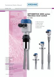
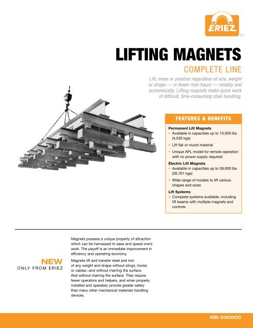
®SAFEHOLD ®APL SERIES<strong>LIFTING</strong><strong>MAGNETS</strong>Lift, move or position in less time, efficientlyand economically, without having to manuallyrelease the magnet. SafeHold ® Lifting Magnetsmake quick work of difficult, time-consumingsteel handling.Eriez’ new SafeHold ® APL Series PermanentLifting Magnets can lift and transfer steel and ironwithout slings, hooks or cables – and, withoutmarring the surface. They require fewer operatorsand helpers, and when properly installed andoperated, provide greater safety than many othermechanical material-handling devices.The SafeHold APL Series is ideal for loadingand unloading steel sheets from burningtables or anywhere that limits operator access.They can be used singly or in multiples on aspreader beam.FeaturesSafeHold APL Series permanent magnets turnoff and on automatically to provide smoothoperation for hundreds of lifting-positioningapplications.• No manual-magnet activation required• No electricity needed, so power failures don’tinterrupt operation• Continuous magnet power until magnet isturned off• No costly D.C. power supply• No batteries to recharge or replace• Designed for flat materials onlySPECIFICATIONSLengthAWidthBHeightShutHeightOpenCModelNumberA B Cin mm in mm in mmAPL-150 15 3/4 400 15 1/4 388 2 13/16 72APL-152 16 3/8 416 17 7/8 454 3 3/4 96APL-154 22 13/16 580 18 11/16 474 3 3/4 96APL-156 29 5/8 753 20 5/8 524 3 3/4 96ModelNumberMax LiftingCapacity w/2:1Safety FactorMaximumBreakawayForcePlateThickness Length WidthHeight(Shut)Height(Open) Eye ID Weightlbs kg lbs kg in mm in mm in mm in mm in mm in mm lbs kgAPL-150 900 425 1800 850 1-1/4 32 10-5/16 262 9-9/16 243 13-3/4 349 17-3/16 436 2 51 167 76APL-152 1,650 750 3,300 1,500 1-1/4 32 10-13/16 275 12 304 16-15/16 430 21-1/2 546 1-7/8 48 291 132APL-154 3,600 1,630 7,200 3,265 2 51 17-1/4 438 12 304 17-5/8 449 22-1/4 566 2-3/8 60 463 210APL-156 5,800 2,630 11,600 5,260 2 51 23 583 13-15/16 354 18-9/16 471 23-1/8 588 2-3/8 60 727 330Note:1. These are actual ratings on flat, clean, polished steel plate.2. Maximum attractive force of each model is approximately twice the Lifting Capacity.3. Thin sheets, rough and irregular surfaces, odd shapes and scale all affect holding power adversely and must be considered in establishing a safety factor.3
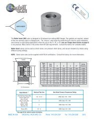
®SAFEHOLD ®EPL SERIES<strong>LIFTING</strong><strong>MAGNETS</strong>EPL Series SafeHold® Magnets areideal for many machine-shop operationsincluding the loading and unloading of thisburn table.Lift, move or position in less time, efficiently andeconomically. SafeHold Lifting Magnets makequick work of difficult, time-consuming steelhandling.Eriez’ new SafeHold ® EPL Series Permanent LiftingMagnets can lift and transfer steel and iron withoutslings, hooks or cables--and without marring thesurface. And without marring the surface. Theyrequire fewer operators and helpers, and whenproperly installed and operated, provide greatersafety than other mechanical materials handlingdevices.SafeHold ® EPL Series permanent magnetsturn on and off manually to provide smoothoperation for hundreds of lifting and positioningapplications.• No electricity needed, so power failures don’tinterrupt operation• Continuous magnet power until magnet isturned off• No costly D.C. power supply• No batteries to recharge or replace• Designed for flat materials onlyIdeal for carrying semi-finished products with flatsurfaces such as machine parts, press molds forforming, steel plate, etc. Permanent magnetictype, requiring no power supply, thus eliminatinghazards due to failure of wiring system or serviceinterruptions. Small, lightweight magnet featurespowerful magnetic force.Operation is easy. Internal on/off change-overmechanism eliminates possible scratches on thework surface when loading/unloading.Combine several SafeHold lift magnets toconform to the specific shape and weight ofcomplex work pieces.EYE IDOffOnHeightL1WidthL2ModelNumberMax LiftingCapacity w/2:1Safety FactorMaximumBreakawayForceTestPlateThicknessDimensionsL1 L2 Width Height Eye ID Weightlbs kg lbs kg in mm in mm in mm in mm in mm in mm lbs kgEPL-121 650 295 1300 590 1-1/4 32 2-7/8 73 4-11/16 119 9-1/2 241 7-1/8 181 1-3/8 37 17EPL-154 4000 1814 8000 3629 1-1/2 38 11-7/16 291 14-3/8 365 12 305 9 229 2-1/4 225 102EPL-157 7500 3402 15000 6804 2 51 20 508 22-15/16 583 12 305 9 229 2-1/2 400 182EPL-197 10000 4536 20000 9072 2 51 21-3/8 543 24-5/16 618 14 356 10-5/8 270 2-1/2 640 290Note:1. These are actual ratings on flat, clean, polished steel plate.2. Maximum attractive force of each model is approximately twice the Lifting Capacity.3. Thin sheets, rough and irregular surfaces, odd shapes and scale all affect holding power adversely and must be considered in establishing a safety factor.4
®SAFEHOLD ®RPL SERIES<strong>LIFTING</strong><strong>MAGNETS</strong>(CONT.)SPECIFICATIONSModelNumberMax Lifting Capacities Max Breakaway Force Maximum Dia.When LiftingFlat Steel Round Steel FlatRoundRounds(2:1 SF)(2:1 SF)SteelSteel* w/o Pole ShoesTestPlateThicknesslbs kg lbs kg lbs kg lbs kg in mm in mm**RPL-3 300 136 150 68 600 272 300 136 3 76 1 25RPL-11 1,100 500 550 250 2,200 1,000 1,100 500 5 127 1 25RPL-22 2,200 1,000 1,100 500 4,400 2,000 2,200 1,000 6.5 165 1-1/4 32RPL-35 3,500 1,588 1,750 795 7,000 3,175 3,500 1,588 10 254 2 51RPL-70 7,000 3,175 NR NR 14,000 6,350 NR NR NR NR 2 51Note:1. These are actual ratings on flat, clean, polished steel plate.2. Maximum attractive force of each model is approximately twice the Lifting Capacity.3. Thin sheets, rough and irregular surfaces, odd shapes and scale all affect holding power adversely and must be considered in establishinga safety factor.* Based on maximum recommended material diameter.** Not for use on plates less than 1 1/2" [38] thick. They are too thin to operate the handle.7
®SELECTO ®CONTINUOUS-DUTY ELECTRO<strong>LIFTING</strong><strong>MAGNETS</strong>Lightweight, power packed to provide reliable,fast lifts for hundreds of applications• Easy to install, easy to use• Eliminate hooks, slings or grabs• Use individually or in multiples• 100-percent duty cycle• Fully encapsulated moisture-proof coil• Built-in solid-state rectifier and drop-controlcircuit (Model ST)• Standard voltage of the SL Selecto Magnet is115VDC; standard voltage of the ST SelectoMagnet is 115VAC; other voltages availableupon request• Copper-wound coilSL SeriesThe SL Series requires a compact Eriez variablevoltagerectifier controller or a fixed-voltagerectifier to furnish the desired D.C. power fromany A.C. source. The controller can be mountedin any convenient location near the area wherethe lifting magnet is used.ST SeriesThe STD Series units have a miniaturizedrectifier/drop control circuit with a “Lift-Off-Drop”switch attached to the magnet. This eliminatesthe need for a separate rectifier and can brieflycancel out any residual magnetism to allow theload to be easily discharged from the magnet.SPECIFICATIONSDrop-ForgedLifting EyeC LEC LEC LC LCDDCNOTES:* Taken with magnet in hot condition** 230VDC Optional - Wattage may vary with voltagesModelNumberMax LiftingCapacity w/2:1Safety Factor*MaximumBreakawayForce*TestPlateThickness A B C D Elb kg lb kg in mm in mm in mm in mm in mm in mm Watts lb kgSL-4 375 170 750 340 1 25 4 102 2-3/4 70 4-7/16 113 1 25 7/8 22 38 9 4.1SL-5 1,030 468 2,060 934 1 25 5-9/16 141 4-1/8 105 7-1/8 181 1-3/4 44 1-3/8 35 72 22 10.0SL-8 2,800 1,270 5,600 2,540 2 50 8-5/8 219 5 127 9-1/4 235 2-3/8 60 1-13/16 46 150 74 33.5SL-10 4,500 2,042 9,000 4,082 2 50 10-3/4 273 5-1/4 133 10-7/16 265 2-15/16 75 2-3/16 56 228 139 63.0SL-12 8,600 3,900 17,200 7,802 3 76 12-3/4 324 6-9/16 167 11-3/4 298 2-15/16 75 2-3/16 56 250 240 109.0SL-14 9,800 4,442 19,600 8,891 3 76 14 356 7-1/4 184 12-3/4 324 3-1/8 79 2-1/2 64 307 320 145SL-16 12,125 5,500 24,250 11,000 3-3/4 95 16 406 8-1/8 206 14 356 3-1/8 79 2-1/2 64 382 470 213ST-4D 375 170 750 340 1 25 4 102 4-1/2 114 5-5/8 143 1 25 7/8 22 38 10 5ST-5D 1,030 468 2,060 934 1 25 5-9/16 141 5-5/16 135 8-5/16 211 1-3/4 44 1-3/8 35 72 25 11ST-8D 2,800 1,270 5,600 2,540 2 50 8-5/8 219 6-1/4 159 10-1/2 267 2-3/8 60 1-13/16 46 150 80 36ST-10D 4,500 2,042 9,000 4,082 2 50 10-3/4 273 6-1/2 165 11-11/16 297 2-15/16 75 2-3/16 56 228 145 66ST-12D 8,600 3,900 17,200 7,802 3 76 12-3/4 324 7-13/16 198 13 330 2-15/16 75 2-3/16 56 250 247 112ST-14D 9,800 4,442 19,600 8,891 3 76 14 356 9-1/4 235 14 356 1-1/8 29 2-1/2 64 307 330 150ST-16D 12,125 5,500 24,250 11,000 3-3/4 95 16 406 10-1/8 257 15-1/4 387 1-1/8 29 2-1/2 64 382 480 218115VDC**Weight8
®RECTANGULARELECTRO<strong>LIFTING</strong><strong>MAGNETS</strong>Eliminate slings, hooks, cables and the manpowerneeded for dangerous attaching work• Heavy-duty welded-steel magnet body• Magnet coil sealed against moisture• Weather-resistant outlet box• 50-percent duty cycle: 15 minutes maximum“on” time• 100-percent duty cycle available• Shallow, three-pole field for thin, flat loads• Copper-wound coilThree standard models and lengths from nineinches (229 mm) to 96 inches (2438 mm) allowyou to size the magnet to the job. Eriez’ smallestsingle unit has a holding power (with nosafety factor) of 1860 pounds (845 kg); thelargest, 38.8 tons (35,240 kg).SPECIFICATIONS4 1/8"4 1/4"Magnet LengthEE6"15211"2791"256"152Magnet Length17"432AMagnet Length9
®RECTANGULARBI-POLAR<strong>LIFTING</strong><strong>MAGNETS</strong>Specifically designed to provide greater contactand holding strength on castings, forgings,plates and structural shapes• Three widths; 13 sizes• For pipe handling, round bars, angles, flatsand shapes• Special-shaped pole shoes are available• Deep, two-pole field provides better holdingon round and irregular shapes• Computer-designed coil• Weather-tight welded construction• 50-percent duty cycle (15 minutes maximum“on” time)• 100-percent duty cycle availableEriez Magnetics’ line of Rectangular Bi-PolarMagnets provides an optional variety of poleplateconfigurations which permit maximumcontact areas for pipe, rounds and odd shapes.Bi-polar magnets can be used in either singlemagnetor multiple-magnet applications andwith a variety of suspension systems. Eriezdesigns and builds complete systems includingmagnets, lift beams, power supplies, controlsand battery back-up units.Optional Pole Configurations AvailableRadiused or contoured poles for large rounds.Extended poles for high-temperature applications.Flat poles for thin and heavy loads.SPECIFICATIONSC Dia.WDModels over 24" (610 mm) long have two lifting lugs; all others have one.ModelNumberAMagnetWidthBMagnetHeightCLifting LugHole Diameter D Wlb kg lb kg in mm in mm in mm5 XX 5-1/4 133 8-3/8 213 1 25 9-5/8 245 2-1/4 5710 XX 10-1/4 260 14-1/8 359 1-5/16 32 15-7/8 403 4-1/4 10815 XX 15-1/4 387 22 559 1-3/4 44 22-1/2 572 6-1/4 15913
®SPECIFICATIONSModelNumberMax LiftingCapacity w/2:1Safety Factor*MaximumBreakawayForce*TestPlateThickness Width Length** 115 VDC** Weightlb kg lb kg in mm in mm in mm Watts Amps lb kg512 2,620 1,188 5,240 2,377 4-1/2 114 5-1/4 133 12 305 390 3.4 95 43518 3,930 1,784 7,875 3,572 4-1/2 114 5-1/4 133 18 457 550 4.8 145 66524 5,250 2,382 10,500 4,763 4-1/2 114 5-1/4 133 24 610 700 6.0 195 87536 7,870 3,570 15,740 7,140 4-1/2 114 5-1/4 133 36 914 1,000 8.7 295 134548 10,500 4,762 21,000 9,526 4-1/2 114 5-1/4 133 48 1,219 1,325 11.5 395 1761018 8,880 4,028 17,760 8,056 4-1/2 114 10-1/4 260 18 457 1,125 9.8 435 1981024 11,850 5,376 23,700 10,750 4-1/2 114 10-1/4 260 24 610 1,425 12.4 600 2731036 17,770 8,060 35,540 16,121 4-1/2 114 10-1/4 260 36 914 2,000 17.4 925 4201048 23,700 10,750 47,400 21,501 4-1/2 114 10-1/4 260 48 1,219 2,500 21.7 1,125 5111524 16,800 7,620 33,600 15,241 4-1/2 114 15-1/4 387 24 610 2,400 20.9 1,335 6071536 25,200 11,430 50,400 22,861 4-1/2 114 15-1/4 387 36 914 3,300 28.7 2,065 9391548 33,600 15,240 67,200 30,482 4-1/2 114 15-1/4 387 48 1,219 4,200 36.5 2,685 1,2201560 42,000 19,052 84,000 38,102 4-1/2 114 15-1/4 387 60 1,524 5,100 44.3 3,410 1,550NOTES:* Taken with magnet in hot condition** 230VDC Optional - Wattage may vary with voltage14
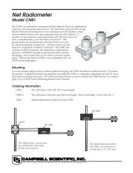
®CIRCULAR<strong>LIFTING</strong><strong>MAGNETS</strong>Eriez’ Circular Lifting Magnets,with computer-designed magneticcircuitry, offer a high lift-to-weightcapability in many applications: insteel mills, ball mills; for furnacecharging and other materialshandlingjobs.Magnets to handle all kinds of steel, especiallyscrap, efficiently and inexpensively• Computer-designed aluminum coil• Fabricated construction• Ribbed, manganese-steel bottom plate• Weatherproof construction• Class H insulation• Standard models 18” and 24” (457 mm and610 mm) in diameter• 75-percent duty cycle; 15 minutes maximum“on” timeEriez’ Circular Lifting Magnets are generalpurposemagnets with many applications: insteel mills, steel service centers, ball mills;for furnace charging and other materialhandlingjobs. The computer design providesa 75-percent duty cycle with a high lift-toweightratio. A triple-sealed terminal boxand super-alloy steel chains are standard.Rectifiers, drop controllers and cable reelsare available as accessories.SPECIFICATIONSCD18" (457 mm) Diameter UnitThe 18” diameter unit isfurnished with a single-chainsuspension assembly andsingle-lead two-conductorpowercord.ModelNumberA B C Din mm in mm in mm in mm18 18 457 9 229 2-3/4 70 5-1/2 14024 24 610 9-1/2 241 3-1/2 89 7 17824" (610 mm) Diameter UnitMagnetDiameterApproximateWeightCurrentRating(Amps)NOTES:Magnets operate on 230 VDC* Based on operating current. For light duty use, size generator for the cold amperes.RecommendedLifting Capacities - Approximate (All Day) AverageGenerator RectifierPlates &Slabs#1 HeavyMelting#2 HeavyMeltingPlatePunchingsCast IronBoringsin mm lb kg Cold Operating kw* kwCable Sizelb kg lb kg lb kg lb kg lb kg18 457 405 184 7 4 1.5 1.5 14/3 1.80 4,000 1,814 175 79 100 45 250 113 90 4124 610 725 329 9 5 2.5 2.5 14/3 1.80 10,000 4,536 280 127 200 91 425 193 170 7715
®FIXED-VOLTAGESILICONRECTIFIERSSilicon Rectifier units specially designed foruse with all types of electromagnetsEriez’ fixed-voltage rectifiers provide fixed voltageD.C. power for all types of electromagnets. Theirdesign uses full-wave bridge silicon rectifiers withavalanche characteristics, eliminating the needfor other components to reduce voltage spikes.A wide range of sizes is available for bothsingle-phase and three-phase operation.Single-phase rectifiers operate from 115/230volts, 50/60 Hz, single-phase A.C. with 120volt D.C. output. Capacities from 500 watts upto 3,000 watts are available.Three-phase rectifiers are suitable for converting230/460 volt, 50/60 Hz, three-phase A.C. toeither 120 volt D.C. or 240 volt D.C. Capacitiesrange from 500 watts up to 25,000 watts. Otherinput voltages are available on request.Standard enclosures are NEMA 1, openventilated, 14-gauge steel cabinets for wallmounting; NEMA 3, weather-proof; NEMA4, water-tight; and NEMA 12 or 9, dust-tightconstructions are available.Eriez’ fixed-voltage rectifiers are designed forfull-capacity operation in ambient temperaturesup to 110°F (43°C) and elevations up to2,000 feet (610 meters) above sea level, withmoderate derating required above these levels.The power supplies are protected with dualelementfuses and with current-limiting fusesmade specifically for the protection of semiconductors.Simplicity of design combined with high qualitycomponents provides years of trouble-freeoperation.SPECIFICATIONSSingle-Phase ModelsNameplatePilotLightSwitchThree-Phase ModelsNameplateSwitchPilotLightCCDIMENSIONS AND WEIGHTSSingle-PhaseModelNumberA B C Weightin mm in mm in mm lb kg5CS11 12-3/16 310 10-3/16 260 6-1/4 160 45 2010CS11 12-3/16 310 10-3/16 260 6-1/4 160 48 2220CS11 16-3/16 410 12-1/4 310 8-1/4 210 55 2530CS11 16-3/16 410 12-1/4 310 8-1/4 210 60 27ELECTRICAL DATASingle-PhaseModelNumberAC InputDC OutputVolts Amps Volts Watts Amps5CS11 115 4.62 120 500 4.1610CS11 115 9.5 120 1,000 8.3420CS11 115 18.5 120 2,000 16.6530CS11 115 27.5 120 3,000 25.017
®SPECIFICATIONSDIMENSIONS AND WEIGHTS Three-PhaseModelNumberA B C Weightin mm in mm in mm lb kg5C 20-1/4 514 16-1/4 413 8 203 160 7210C 20-1/4 514 16-1/4 413 8 203 160 7215C 24-1/4 615 18-1/4 464 10-3/8 265 190 8620C 36-1/4 920 21-1/4 540 10-3/8 265 210 9525C 36-1/4 920 21-1/4 540 10-3/8 265 210 9530C 36-1/4 920 21-1/4 540 10-3/8 265 210 9535C 36-1/4 920 21-1/4 540 10-3/8 265 210 9540C 36-1/4 920 21-1/4 540 10-3/8 265 210 95ELECTRICAL DATA Three-PhaseModelNumberAC InputDC OutputVolts Amps Volts Watts Amps5C21 230 1.51 120 500 4.1610C21 230 3.0 120 1,000 8.315C21 230 4.3 120 1,500 12.520C21 230 6.0 120 2,000 16.725C21 230 7.2 120 2,500 20.930C21 230 8.4 120 3,000 25.035C21 230 9.8 120 3,500 29.240C21 230 11.2 120 4,000 33.350C21 230 14.2 120 5,000 41.760C21 230 17.3 120 6,000 50.075C21 230 22.6 120 7,500 62.510K21 230 30.5 120 10,000 83.312.5K21 230 36.1 120 12,500 104.015K21 230 45.0 120 15,000 125.020K21 230 61.1 120 20,000 167.025K21 230 72.2 120 25,000 208.05C22 230 1.59 230 500 2.1710C22 230 3.0 230 1,000 4.515C22 230 4.5 230 1,500 6.520C22 230 6.0 230 2,000 8.425C22 230 7.2 230 2,500 10.530C22 230 8.4 230 3,000 12.535C22 230 9.8 230 3,500 14.640C22 230 11.2 230 4,000 16.650C22 230 14.2 230 5,000 20.860C22 230 18.2 230 6,000 26.075C22 230 22.6 230 7,500 31.310K22 230 30.5 230 10,000 41.712.5K22 230 37.9 230 12,500 54.015K22 230 45.0 230 15,000 62.520K22 230 61.1 230 20,000 83.325K22 230 75.8 230 25,000 108.0DIMENSIONS AND WEIGHTS Three-PhaseModelNumberA B C Weightin mm in mm in mm lb kg50C 36-1/4 920 21-1/4 540 10-3/8 265 210 9560C 36-1/4 920 21-1/4 540 10-3/8 265 210 9575C 36-1/4 920 21-1/4 540 10-3/8 265 210 9510K 36-1/4 920 21-1/4 540 12-3/8 315 312 14212.5K 36-1/4 920 21-1/4 540 12-3/8 315 376 17115K 36-1/4 920 21-1/4 540 12-3/8 315 376 17120K 45-1/4 1,150 30-1/4 770 16-3/8 415 525 23825K 45-1/4 1,150 30-1/4 770 16-3/8 415 525 238ELECTRICAL DATA Three-PhaseModelNumberAC InputDC OutputVolts Amps Volts Watts Amps5C41 460 0.76 120 500 4.1610C41 460 1.5 120 1,000 8.315C41 460 2.2 120 1,500 12.520C41 460 3.0 120 2,000 16.725C41 460 3.5 120 2,500 20.930C41 460 4.2 120 3,000 25.035C41 460 4.9 120 3,500 29.240C41 460 5.6 120 4,000 33.350C41 460 7.1 120 5,000 41.760C41 460 9.0 120 6,000 50.075C41 460 11.3 120 7,500 62.510K41 460 15.0 120 10,000 83.312.5K41 460 18.8 120 12,500 104.015K41 460 22.6 120 15,000 125.020K41 460 30.6 120 20,000 167.025K41 460 37.7 120 25,000 208.05C42 460 0.80 230 500 2.1710C42 460 1.6 230 1,000 4.515C42 460 2.4 230 1,500 6.520C42 460 3.0 230 2,000 8.425C42 460 3.5 230 2,500 10.530C42 460 4.2 230 3,000 12.535C42 460 4.9 230 3,500 14.640C42 460 5.6 230 4,000 16.650C42 460 7.1 230 5,000 20.860C42 460 9.5 230 6,000 26.075C42 460 11.3 230 7,500 31.310K42 460 15.0 230 10,000 41.712.5K42 460 19.8 230 12,500 54.015K42 460 22.6 230 15,000 62.520K42 460 30.6 230 20,000 83.325K42 460 39.69 230 25,000 108.018
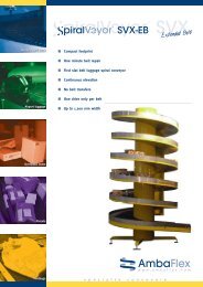
®VARIABLE-VOLTAGERECTIFIERSMODEL/WIRING DIAGRAMIf Drop Control is required, please contact Eriez500-23-11Rating: 230 VAC, 3 Phase, 500 Watts, 8.7 AmpsFinish: Gray Weight: 36 lb/16 kg1K-23-11Rating: 230 VAC, 3 Phase, 1000 Watts, 8.7 AmpsFinish: Gray Weight: 58 lb/26 kg29 mm1 1 /8104 - 5 /16 Dia. Mtg. Holes 8 mm254 mm2 - 7 /8 Dia. 22 mmKnockouts onTop, ottom,& F.S.1 1 /238 mmVoltmeter6 1 /2165 mm2 5 /867 mm114- 13 /32 Dia. Mtg. Holes 10 mm229 mm1 1 /238 mm8 1 /2216 mm14356 mm16 3 /18411 mmOnControlKnob376 mm21533 mm20 1 /4514 mm376 mm28 mm1 3 /32230 VC3 PHLineNameplate12 1 /2311 mmSwitchlk1lk lklk2lk lklk3lk lkLineFusesVar. TransformerYelYelYelOutpostFuses125 mmYelYelYelSilcon ridgeRectifierOffSwitch8 3 /8213 mmVoltmeterRed #16 G Wire5Red +0-115VV D.C. LoadOutputlklk -4230 VC3 PHLinelk1lk2lk316 1 /4413 mmlklklklklklkYelYelYel125 mmYelYelYelOnOff8 5 /8219 mmRed5Red +0-115VV D.C.Outputlklk -42 - 7 /8 Dia.Knockoutson Top,ottom,& F.S.22 mm#14 G Wire(1K-23-11)#12 G Wire(2K-23-11)Load2K-23-11Rating: 230 VAC, 3 Phase, 2000 Watts, 17.4 AmpsFinish: Gray Weight: 75 lb/34 kg5K-23-11Rating: 230 VAC, 3 Phase, 5000 Watts, 34.8 AmpsFinish: Gray Weight: 185 lb/84 kg2 5 /867 mm 114- 13 /32 Dia. Mtg. Holes 10 mm229 mm2 5 /867 mm 16406 mm1 1 /238 mm8 1 /2216 mm21533 mm20 1 /4514 mm376 mm37 1 /2953 mm36 1 /4921 mm16 1 /4413 mm125 mmOnOff8 5 /8219 mm2 - 7 /8 Dia.Knockoutson Top,ottom,& F.S.22 mm6 - 7 /8 Dia. 22 mmon Knockoutson Bottom21 1 /4540 mm1 1 /238 mmOnOff12 5 /8321 mm230 VC3 PHLinelk1lk2lk3lklklklklklkYelYelYelYelYelYelRed5Red +0-115VV D.C.Outputlklk -4#14 G Wire(1K-23-11)#12 G Wire(2K-23-11)Load230 VAC3 PHLineBlk1Blk2Blk3BlkBlkBlkBlkBlkBlkYelYelYelYelYelYelRed5Red +0-115VV D.C.OutputBlkBlk -4#8 GA WireLoad20
®VARIABLE-VOLTAGERECTIFIERSMODEL/WIRING DIAGRAMIf Drop Control is required, please contact Eriez500-43-11Rating: 460 VAC, 3 Phase, 500 Watts, 4.3 AmpsFinish: Gray Weight: 36 lb/16 kg1K-43-11Rating: 460 VAC, 3 Phase, 1000 Watts, 8.7 AmpsFinish: Gray Weight: 58 lb/26 kg2 5 /867 mm11279 mm4- 13 /32 Dia. Mtg. Holes 10 mm2 5 /867 mm13330 mm4 - 7 /16 Dia. Mtg. Holes 11 mmVoltmeter1 1 /238 mm8 1 /2216 mm1 1 /238 mm10 1 /2267 mm21533 mmNameplate20 1 /4514 mmControlKnob376 mm24 3 /4533 mm24 1 /4616 mm376 mm460 VC3 PHLine125 mm16 1 /4413 mmSwitchlk1lk lkYellk2lk lkYellk3lk lkYelLineFusesOutpostFusesVar. TransformerYelYelYelSilcon ridgeRectifierSwitch8 5 /8219 mm2 - 7 /8 Dia.Knockoutson Top,ottom,& F.S.22 mmVoltmeterRed #16 G Wire5Red +0-115VV D.C. LoadOutputlklk -4460 VC3 PHLinelk1lk2lk3lklklk18 1 /4464 mmlklklkYelYelYel125 mmYelYelYel10 5 /8270 mmRed5Red +0-115VV D.C.Outputlklk -42 - 7 /8 Dia.Knockoutson Top,ottom,& F.S.22 mm#14 G WireLoad2K-43-11Rating: 460 VAC, 3 Phase, 2000 Watts, 17.4 AmpsFinish: Gray Weight: 162 lb/73 kg5K-43-11Rating: 460 VAC, 3 Phase, 5000 Watts, 34.8 AmpsFinish: Gray Weight: 216 lb/98 kg2 5 /867 mm13330 mm4 - 7 /16 Dia. Mtg. Holes 11 mm2 5 /867 mm 16406 mm4 - 7 /16 Dia. Mtg. Holes 11 mm1 1 /238 mm27 1 /2699 mm26 1 /4667 mm376 mm37 1 /2953 mm11 1 /2292 mm36 1 /4921 mm460 VC3 PHLinelk1lk2lk3lklklk18 1 /4464 mmlklklkYelYelYel1 1 /238 mmYelYelYel12 5 /8321 mmRed5Red +0-115VV D.C.Outputlklk -42 - 7 /8 Dia.Knockoutson Top,ottom,& F.S.22 mm#12 G WireLoad460 VAC3 PHLineBlk1Blk2Blk3BlkBlkBlk6 - 7 /8 Dia. 22 mmKnockouts on Bottom21 1 /41 1 /2540 mm38 mmAuto TransformerBlk BlkYelBlk BlkYelYelYelYelBlk BlkYel12 5 /8321 mmRed5Red +0-115VV D.C.OutputBlkBlk -4#8 GA WireLoad21
®LIFT MAGNETDROPCONTROLLERLIFT-MAGNET DROPCONTROLLERWhen a D.C. electromagnet is actuated andholds a load, magnetic lines of force areestablished in the magnet and the load.These lines of force, generated by themagnetomotive force of the magnet, remain inplace at full strength while the magnet is on.When the magnet is turned off, the linesdiminish to zero, or near zero. If there are airgaps in the magnetic circuit, the load will bedropped immediately. However, if there isclose contact between the magnet and theload, some residual magnetism may remainin the iron circuit for some time after turnoff.This residual magnetism sometimes holdsthe load after the power to the magnet hasbeen turned off. The residual magnetism canbe cancelled out by briefly applying a reversevoltage and current to the magnet, thusdisheveling the load. This is the function ofthe lift-magnet drop controller.There are two basic types of drop controllersused by Eriez Magnetics for most applications.The first is the manual type which carries outthe on-off-reverse functions in full control ofthe operator. It is best suited for variableloading, especially where it is necessary todrop parts of the load while retaining others.The second is the automatic-type dropcontroller which carries out on-off-reversefunctions automatically once it has been setup and adjusted for a certain load. Theautomatic type is best suited for just one kindof a load to be lifted and dropped repeatedly.MANUAL-TYPE DROPCONTROLLERA manual-type drop controller is usuallyactuated by a three-position drum-type masterswitch (a three-position push-button masterswitch is used infrequently). The drum switchusually has positions labeled “on-off-reverse”or “on-off-drop,” in that order. It is usuallyspring loaded so it returns automatically tothe “off” position.While the magnet is energized and holdingsheets of steel, the operator may want to dropthe bottom sheet while retaining the rest. Hewould position the load over the desireddischarge area, throw the switch quickly throughthe “off” position and jog the “drop” positiononce, twice, or enough times to cause the sheetto drop off. He would then quickly throw theswitch back through the “off” position to the “on”position in order to hold the rest of the load.In jogging the “drop” or “reverse” positionof the switch, the operator is putting shortbursts of reverse current through the poles ofthe magnet, cancelling the residual magneticattraction in the magnet and load until thebottom sheet drops. The remaining residualforce is enough to hold the balance of theload until the switch is returned to the “on”position, providing this is done quickly.AUTOMATIC-TYPE DROPCONTROLLERThe automatic-type drop controller is usuallyactuated by a drum or maintained-type pushbuttonswitch. In either case, the switch wouldbe labeled “lift” and “drop.”This type of drop controller is best suited forjust one kind of load. However, by adjusting arheostat inside the drop controller enclosure,it is possible to vary the reverse current tomeet various loading conditions. Decreasingthe amount of reverse current to the magnetholding a particular load will result in holdingthat load for an increased time period. It is alsopossible to use certain types of pilot devices ormaster switches to cause the drop controller todribble the load like a manual-drop controller.There are several types of pilot devices ormaster switches which are suitable for anautomatic-type drop controller. The leastexpensive is one which will only lift or drop aparticular load. That is, when the “drop” buttonis pushed, the magnet is turned off, and the dropcontroller reverses polarity to clean the magnet.The automatic-type drop controller can alsobe used with a notched-position master switchor maintained-type push-button switch whichallows an operator to drop only portions of theload, like the manual-drop controller. This canbe done by moving the master switch to the“drop” position (or pushing the “drop” button)only the distance necessary to momentarilyde-energize the lift contactor. With the reversecurrentrheostat preset for lifting steel sheets,this will cause one sheet at a time to fall fromthe bottom of the stack. Once the desiredportion of the load has been dropped, theoperator must quickly remove his hand fromthe lever or push button to allow the switch toreturn to the lift position.Operating either a manual or automatic dropcontroller as described requires a certain amountof skill—similar to operating an automobileclutch and shift lever. The certain touch requiredcan only be acquired by practice.22
®ERIEZBATTERYSTANDBYSYSTEMSThese assemblies, in general, consist ofrectifiers, a drop controller, batteries, batterycase, battery charger, main switch and alarmsystem with pendant-control station.They are used in conjunction with EriezElectro Lifting Magnets. If A.C. power failsduring a lift, this system immediately takesover supplying the necessary power to feedthe particular magnets for a period of 10 to 15minutes, allowing the lift beam to be manuallylowered to the ground or the area cleared ofequipment and personnel.An alarm system is furnished with this package.Various alarms are available along withflashing lights, buzzers or horns.This equipment consists of:• Main control cabinet containing the rectifieddirect-current power supply, control relays,electronic-standby switching, circuits andbattery-charger contact• Battery boxes containing lead-acid batteries• Automatic battery charger to maintain thebatteries at maximum capacity• Drop control for the proper release of theload in the drop modePrime power is supplied by the rectifiercontrol unit. Standby power is provided bythe lead-acid batteries. Either source iscapable of being switched into the magnetload with a remote-control station.These systems may contain continuoustrickle charging of the batteries. Thisdepends on the particular application.Low charging of the batteries will beautomatically regulated in accordance withthe condition of the batteries. High-ratecharging is also available through a switchon the battery charger for fast charging orfor equalizing.In the event that the batteries becomedischarged to the point that further loadcarryingcapacity is reduced or the batterysource becomes inoperative for any reason,a low-voltage alarm relay will activate. Thealarm relay operates a set of contacts thatthe customer can wire to an alarm system.If the A.C. power-line voltage should fail,the battery pack will automatically sustainthe lift. Load carrying capability is reducedif the battery source becomes inoperativefor any reason.The control equipment is generally ratedNEMA 1 but is available in other NEMA ratings.The control stations, such as the operatorcontrol station, must be convenientlylocated for both operation and maintenance.The magnet control requires access formaintenance only.Complete wiring diagrams are furnishedwith each of these battery-standby systems.Battery-standby systems are designed andbuilt to the particular lift-beam assemblybeing furnished. Drawings can be furnishedupon request.23
ABOUTERIEZMAGNETICSSTATE-OF_THE_ARTENGINEERINGComputerized systems help improveEriez’ efficiency and services throughoutthe Company. The corporate engineeringdepartment’s CAD system, withcompatible systems in Eriez officesaround the world, enables instant accessto engineering drawings and informationrequests from any location. The samedesigns, drawings and high-qualitystandards are followed at all plantoperations so that, no matter whichEriez manufacturing facility produces theequipment, Eriez customers are assuredof quality on a worldwide basis. This isespecially important to multi-nationalusers of Eriez equipment who wish tostandardize production lines throughone supplier.WORLD-CLASSMANUFACTURINGEriez maintains a global perspectivethrough manufacturing facilities at itsUSA headquarters, as well as in Australia,Brazil, Canada, China, India, Japan,Mexico, South Africa and the UnitedKingdom. To maintain its world-classposition, Eriez reinvests its profits inmodern manufacturing equipment,applied research and development,highly qualified engineering and designstaff, and up-to-date testing facilities.Computerized order entry assures consistentquality and timely response on aworldwide basis. Eriez personnel teamsreflect the same customer-orientedphilosophy of “Right. On Time” – nomatter where they are located.WORLD-CLASSMANUFACTURINGEriez maintains industry’s largest magnetic, vibratory and metal detection testlabratory at its Technical Center,adjacent to the headquarters plant, inErie, Pennsylvania, USA. Here, customerproducts and raw materials are analyzedconfidentially, and ways to separate ormove, screen or detect them moreefficiently and economically are thensuggested. Both feasibility and definitivestudies are conducted. Over 100 piecesof specialized test equipment are onhand. Customers are encouraged toparticipate in the testing. Basic materialsseparation and material-movement testequipment is also available at Eriezaffiliates worldwide.Service & RepairContact Eriez for information on lift magnet recertificationNote: Some safety warning labels or guarding may have been removed before photographing this equipmentEriez, Eriez Magnetics, SafeHold and Selecto are registered trademarks of Eriez Manufacturing Co., Erie, PA©2009 Eriez Magnetics • All Rights ReservedWeb Site: http://www.eriez.come-mail: eriez@eriez.comTelephone 814/835-6000 • 800/345-4946 • Fax 814/838-4960 • International Fax 814/833-3348HEADQUARTERS: 2200 Asbury Road, P.O. Box 10608, Erie, PA 16514-0608 U.S.A.MANUFACTURING : Australia • Brazil • Canada • China • India • Japan • Mexico • South Africa • United Kingdom • United StatesWorld Authority in Advanced Technology for Magnetic, Vibratory and Inspection Applications609-6M-SBC-AP Eriez Manufacturing Co. Printed in USA®