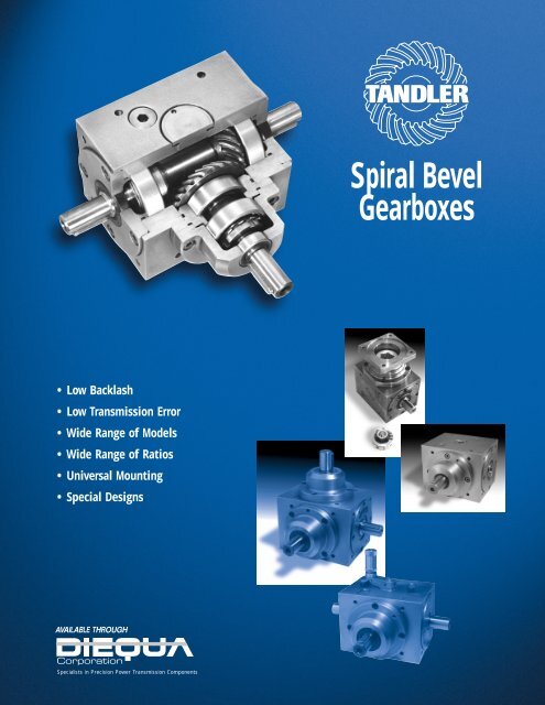
Spiral Bevel Gearboxes - Diequa Corporation
Spiral Bevel Gearboxes - Diequa Corporation
Spiral Bevel Gearboxes - Diequa Corporation
- No tags were found...

You also want an ePaper? Increase the reach of your titles
YUMPU automatically turns print PDFs into web optimized ePapers that Google loves.
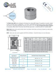
SIZINGSizing <strong>Spiral</strong> <strong>Bevel</strong> <strong>Gearboxes</strong>SIZING SPIRAL BEVEL GEARBOXESPertinent Data1. Input speed.2. Gear ratio.3. Horsepower requirement.4. Method of shaft connection.5. Mounting position.Explanation of SymbolsTo select any gearbox, use the appropriate chartsand tables in the pages that follow. All of them usethe following symbols:n 1 = rpm on pinion d 1n 2 = rpm on shaft d 2i = gear ratio = n 1 /n 2d = a shaft or a pinionHp = horsepowerM = torqueMd 1 = input torque, in Newton-meters, NmMd 2 = output torque, in Newton-meters, NmNm = Newton-metersN 1 = input power, in kilowatts, kWN 2 = output power, in kilowatts, kWC = operational factorAll Tandler gearboxes are delivered with the appropriatequantity and type of oil for normal operation. For speciallubrication and mounting requirements, consult theTechnical Data section, page 32.Pinion d 1Shaft d 24
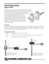
SIZINGSizing Charts<strong>Spiral</strong> <strong>Bevel</strong> <strong>Gearboxes</strong>SIZING SPIRAL BEVEL GEARBOXESThe following charts indicate the size gearbox you’ll requireas a function of output torque and input rpm for a specificrange of gear ratios.Speed-reducingGear Ratio of 1:1 Gear Ratios of 1.25:1 and 1.5:1*1Nm = 8.85 in. lbs.Selection note: Lines represent the maximum capacity of each size.6
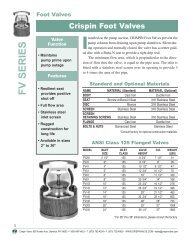
Gear Ratios of 1.75:1 and 2:1 Gear Ratios of 2.5:1 and 3:1SIZINGGear Ratio of 3.5:1 and 4:1 Gear Ratio of 5:1 and 6:1SIZING SPIRAL BEVEL GEARBOXES*1Nm = 8.85 in. lbs.7
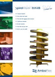
SIZINGSizing Charts<strong>Spiral</strong> <strong>Bevel</strong> <strong>Gearboxes</strong>SIZING SPIRAL BEVEL GEARBOXESSpeed-increasingGear Ratios of 1:1.25 and 1:1.5 Gear Ratios of 1:1.75 and 1:2*1Nm = 8.85 in. lbs.Selection note: Lines represent the maximum capacity of each size.8
STANDARDStandard Right AngleSpeed-Reducing <strong>Spiral</strong> <strong>Bevel</strong> GearboxSPEED REDUCINGAvailable RatiosStandard gearbox is available in 1:1and 10 speed-reducing ratios:1.25:1 3:11.5:1 3.5:11.75:1 4:12:1 5:12.5:1 6:1Internal Gear ArrangementsRight angle 1:1 or speed reduction from shaft d 1 to d 2Available in 8 sizes with 1:1 or 10 speed reducing ratios.Schematic:10
DimensionsSizeSTD 00*STD 01*STD A1*STD B1*STD C1*STD D1STD E1STD F1SizeSTD 00*STD 01*STD A1*STD B1*STD C1*STD D1STD E1STD F1l 23035456085100120150a 80110140170210260330400g1314141818232940b110145175215260330430530øc j774102130160195245310380Ratios i = 1:1, 1.25:1, 1.5:1, 1.75:1, 2:1, and 2.5:1ød 2j61422324255657590i = 1:1 to 2.5:1d 1øo ørd 1j6 l 1 m 1DIN 33214223242556575903035456085100120150110135165210275340435550527090110135150230270M6M8M10M12M16M16M20M24Generale 6082105130160200260320KeyDIN 68855x56x610x812x816x1018x1120x1225x14m 288.5111137172220270340420Ratios i = 3:1SizeSTD 00*STD 01*STD A1*STD B1*STD C1*STD D1STD E1STD F1f3.53.54.54.55.05.05.05.0l 2303545688595120150g1314141818322940h4045506585110150200k 1 )M6M8M10M12M16M16M20M24rDIN 332M6M8M10M12M16M16M20M24i = 3:1d 1øo ørd 1j6 l 1 m 1DIN 332122232363855557525354555658585120105135165205255325400520527090100135135190270M5M8M10M12M12M16M16M20d 2KeyDIN 68855x56x610x812x816x1018x1120x1225x14KeyDIN 68854x46x610x810x810x816x1016x1020x12STANDARDSPEED REDUCINGRatios i = 3.5:1Ratios i = 4:1Sizel 2gi = 3.5:1d 1øo ørd 1j6 l 1 m 1DIN 332KeyDIN 6885Sizel 2gi = 4:1d 1øo ørd 1j6 l 1 m 1DIN 332KeyDIN 6885STD 00*STD 01*STD A1*STD B1*STD C1*STD D1STD E1STD F130354568859512015013141423182829401216202632425060253032454570759510513015220023531039049552708080105110190200M5M6M8M8M10M12M16M164x45x56x68x710x812x814x918x11STD 00*STD 01*STD A1*STD B1*STD C1*STD D1STD E1STD F13035456885951201501314142318282940916202632425060203032454570759510013015220023531039049547708080105110190200M4M6M8M8M10M12M16M163x35x56x68x710x812x814x918x11Ratios i = 5:1Ratios i = 6:1Sizel 2gi = 5:1d 1øo ørd 1j6 l 1 m 1DIN 332KeyDIN 6885Sizel 2gi = 6:1d 1øo ørd 1j6 l 1 m 1DIN 332KeyDIN 6885STD 00*STD 01*STD A1*STD B1*STD C1*STD D1STD E1STD F1--3545688595120150--14142418232940--12162226324255--22304045587085--122150195235298385485--55657095105190200--M5M6M8M8M10M12M16--4x45x56x68x710x812x816x10STD 00*STD 01*STD A1*STD B1*STD C1*STD D1STD E1STD F1--3545688595120----141424182329----101216202640----223030404570----122150185230285385----50557095105190----M4M5M6M8M8M10----3x34x45x56x68x712x8--Dimensions in mmRatio i = d 1 :d 2 = n 1 :n 21) Screwed-in length = k • 1.5* Available in Meehanite and aluminum versionSubject to changesRadial Load CapacitiesSizei = 1:1 to 3:1 i = 3.5:1 to 6:1 i = 1:1 to 3:1 i = 3.5:1 to 6:1Sized 1 d 2 d 1 d 2 d 1 d 2 d 1 d 2STD 00STD 01STD A1STD B1300 N500 N1200 N1750 N320 N1000 N2500 N3500 N--450 N1000 N1500 N--1000 N2500 N3500 NSTD C1STD D1STD E1STD F13000 N3500 N4000 N6000 N4500 N7000 N8500 N10,000 N2000 N2400 N2800 N3500 N4500 N7000 N8500 N10,000 NThe figures in the table above are provided for reference only. Speed, torque, direction of rotation, and direction of applied force will affect the true radial load capacity value.Please consult your DieQua representative.N = .22 lbs.Values are higher with tapered bearing optionOrdering ExampleSTD A1 2:1 IIIType Size Total Ratio Gear Arrangement Special Design (Optional)11
STANDARDStandard Right AngleSpeed-Increasing <strong>Spiral</strong> <strong>Bevel</strong> GearboxSPEED INCREASINGAvailable RatiosStandard gearbox is available in4 speed-increasing ratios:1:1.25 1:1.751:1.5 1:2Internal Gear ArrangementsRight angle speed increasing from shaft d 1 to d 2Available in 8 sizes with 4 speed increasing ratios.Schematic:12
DimensionsRatios i = 1:1.25, 1:1.5, 1:1.75, 1:2i= 1:1.25 and 1:1.5Generald 1 d 2Typea b c ø j7 d ø 1j6 e m 1 l 1 f g h k 1 ) o ø keySTD 00STD 01STD A1STD B1STD C1STD D1STD E1STD F1Dimensions in mmRatio i = d 1 :d 2 = n 1 :n 21) Screwed-in length = k • 1.5Subject to changes80 110 74 14 60 110 30 3.5 13 40 M 6 52110 145 102 22 82 135 35 3.5 14 45 M 8 70140 175 130 32 105 165 45 4.5 14 50 M10 90170 215 160 42 130 210 60 4.5 18 65 M12 110210 260 195 55 160 275 85 5.0 18 85 M16 135260 330 245 65 200 340 100 5.0 23 110 M16 150330 430 310 75 260 435 120 5.0 29 150 M20 230400 530 380 90 320 550 150 5.0 40 200 M24 270rthreadDIN6885M 6 5 x 5M 8 6 x 6M10 10 x 8M12 12 x 8M16 16 x 10M16 18 x 11M20 20 x 12M24 25 x 14Engineering note:For ratios 1:1.75 and 1:2, the d 2 shaft diameter decreases in size.Radial Load CapacitiesSizei = 1:2 to 1:1 i = 1:2 to 1:1Sized 1 d 2 d 1 d 2d ø 2j6 l 2 m 214 30 88.522 35 11132 45 13742 60 17255 85 22065 100 27075 120 34090 150 420rthreadkeyDIN6885M 6 5 x 5M 8 6 x 6M10 10 x 8M12 12 x 8M16 16 x 10M16 18 x 11M20 20 x 12M24 25 x 14i= 1:1.75 and 1:2d ø 2j6 l 2 m 212 25 83.516 30 10624 42 13428 50 16238 60 19550 80 25050 90 31065 130 400rthreadd 2keyDIN6885M 5 4 x 4M 6 5 x 5M 8 8 x 7M 8 8 x 7M12 10 x 8M16 14 x 9M16 14 x 9M16 18 x 11STANDARDSPEED INCREASINGSTD 00STD 01STD A1STD B1300 N500 N1200 N1750 N320 N1000 N2500 N3500 NSTD C1STD D1STD E1STD F13000 N3500 N4000 N6000 N4500 N7000 N8500 N10,000 NThe figures in the table above are provided for reference only. Speed, torque, direction of rotation,and direction of applied force will affect the true radial load capacity value.Please consult your DieQua representative.N = .22 lbs.Values are higher with tapered bearing optionOrdering ExampleSTD A1 1:2 IIIType Size Total Ratio Gear Arrangement Special Design (Optional)13
EAAuxiliaryType EA One-way Auxiliary Branch-off <strong>Spiral</strong> <strong>Bevel</strong> GearboxONE-WAY AUXILIARYAvailable RatiosType EA gearbox is available in 1:1and 10 speed-reducing ratios:1.25:1 3:11.5:1 3.5:11.75:1 4:12:1 5:12.5:1 6:1and 4 speed-increasing ratios:1:1.25 1:1.751:1.5 1:2One input and up to three output shafts in one plane.Engineering note: d 1 and d 5 operate at the same speed.Internal Gear ArrangementsSchematic:d 1d 2DimensionsThe dimensions for the 8 sizes of speed-reducing ratiosare the same as those for STANDARD speed-reducinggearboxes. See the table on page 11.The dimensions for 8 sizes of speed-increasing ratiosare the same as those for STANDARD speed-increasinggearboxes. See the table on page 13.14
Monitoring the Oil LevelAuxiliary pinion EA style gearboxes may requirespecial oil level monitoring. When a one-way EAauxiliary gearbox is mounted vertically, the normaloil level sight-glass is used to monitor the oil level.When the gearbox is mounted horizontally, thenormal sight-glass can no longer be used. An externalsight-glass must be installed. The schematic at rightindicates the various positions available. This isTandler special design S-545. When ordering agearbox with this feature, please specify this specialdesign number and position of the sight-glass:(example: A1 EA-III 1:1 S-545-A).Also see page 32 for additional lubricationinformation, or consult your DieQua representative.Vertical Shaft Applications<strong>Gearboxes</strong> mounted with a shaft in a verticalposition will require special lubrication options. Thebearings supporting the upper portion of the verticalshaft generally do not receive sufficient quantities ofoil for proper lubrication and cooling. Severaloptions exist:EAONE-WAY AUXILIARY1. For vertical pinions S515 d1:The pinion is supported by two preloaded angularcontact ball bearings. The lower bearing isreplaced by a sealed bearing, and the pinion cavityis filled with grease.2. For vertical shafts S515 d2:The ball bearing supporting the upper portion ofthe vertical shaft is replaced with a permanentlylubricated sealed ball bearing.Radial Load CapacitiesSizei = 1:2 to 3:1 i = 3.5:1 to 6:1 i = 1:2 to 3:1 i = 3.5:1 to 6:1Sized 1 = d 5 d 2 d 1 = d 5 d 2 d 1 = d 5 d 2 d 1 = d 5 d 2STD 00STD 01STD A1STD B1300 N500 N1200 N1750 N320 N1000 N2500 N3500 N--450 N1000 N1500 N--1000 N2500 N3500 NSTD C1STD D1STD E1STD F13000 N3500 N4000 N6000 N4500 N7000 N8500 N10,000 N2000 N2400 N2800 N3500 N4500 N7000 N8500 N10,000 NThe figures in the table above are provided for reference only. Speed, torque, direction of rotation, and direction of applied force will affect the true radial load capacity value.Please consult your DieQua representative.Note: d 1 = d 5N = .22 lbs.Values are higher with tapered bearing optionOrdering ExampleSTD A1 2:1 EAIIIType Size Total Ratio Gear Arrangement Special Design (Optional)15
TWO AND THREE-WAY AUXILIARY16ZAAuxiliaryType ZA Two- and Three-way AuxiliaryBranch-off <strong>Spiral</strong> <strong>Bevel</strong> <strong>Gearboxes</strong>d 3 / d 4One input and up to five output shafts make thisgearbox an extremely versatile option for customapplications.d 1Schematic:d 2d 5Available RatiosType ZA gearbox is available in10 speed-reducing ratios:1.25:1 3:11.5:1 3.5:11.75:1 4:12:1 5:12.5:1 6:1and 4 speed-increasing ratios:1:1.25 1:1.751:1.5 1:2(Note: 1:1 ratio not available).DimensionsThe dimensions for the 8 sizes of speed-reducingratios are the same as those for STANDARD speedreducinggearboxes. See the table on page 11.The dimensions for 8 sizes of speed-increasing ratiosare the same as those for STANDARD speedincreasinggearboxes. See the table on page 13.Monitoring the Oil LevelAuxiliary pinion ZA style gearboxes may requirespecial oil level monitoring. For a two-way ZAauxiliary gearbox, the normal oil level sight-glassmay be used only if the face of the gearbox with thesight-glass is mounted horizontal and is visible. Forall three-way ZA auxiliary gearboxes, an external oillevel sight-glass must be used. The schematic belowleft indicates the various positions available. This isTandler special design S-545. When ordering agearbox with this feature, please specify this specialdesign number and position of the sight glass:(example: A1 ZA-III 2:1 S-545-A).Also see page 32 for additional lubricationinformation, or consult your DieQua representative.Vertical Shaft Applications<strong>Gearboxes</strong> mounted with a shaft in a verticalposition will require special lubrication options. Thebearings supporting the upper portion of the verticalshaft generally do not receive sufficient quantities ofoil for proper lubrication and cooling. Severaloptions exist:1. For vertical pinions S515 d1:The pinion is supported by two preloaded angularcontact ball bearings. The lower bearing isreplaced by a sealed bearing, and the pinion cavityis filled with grease.2. For vertical shafts S515 d2:The ball bearing supporting the upper portion ofthe vertical shaft is replaced with a permanentlylubricated sealed ball bearing.
Internal Gear ArrangementsSPEED REDUCING*ZA IZA VIIZA ISPEED INCREASING*ZA VIIZAZA IIZA IIIZA IVZA VIIIZA IXZA X2 WAYAUXILIARYZA IIZA IIIZA IVZA VIIIZA IXZA XTWO AND THREE-WAY AUXILIARYZA VSPEED REDUCINGZA XIZA VSPEED INCREASINGZA XIZA VIZA XII3 WAYAUXILIARYZA VIZA XII* Note: 1 shaft runs slower. All other shafts run faster and at the same speedRadial Load CapacitiesSizei = 1:2 to 3:1 i = 3.5:1 to 6:1 i = 1:2 to 3:1 i = 3.5:1 to 6:1Sized 1 = d 3 = d 4 d 2 d 1 = d 3 = d 4 d 2 d 1 = d 3 = d 4 d 2 d 1 = d 3 = d 4 d 2STD 00STD 01STD A1STD B1300 N500 N1200 N1750 N320 N1000 N2500 N3500 N--450 N1000 N1500 N--1000 N2500 N3500 NSTD C1STD D1STD E1STD F13000 N3500 N4000 N6000 N4500 N7000 N8500 N10,000 N2000 N2400 N2800 N3500 N4500 N7000 N8500 N10,000 NThe figures in the table above are provided for reference only. Speed, torque, direction of rotation, and direction of applied force will affect the true radial load capacity value.Please consult your DieQua representative. Note: d 1 = d 3 = d 4 N = .22 lbs.Values are higher with tapered bearing optionOrdering ExampleSTD A1 2:1 ZAIIIType Size Total Ratio Gear Arrangement Special Design (Optional)17
HWHollow ShaftType HW Hollow Shaft <strong>Spiral</strong> <strong>Bevel</strong> GearboxHOLLOW SHAFTAvailable RatiosType HW gearbox is available in 1:1and 10 speed-reducing ratios:1.25:1 3:11.5:1 3.5:11.75:1 4:12:1 5:12.5:1 6:1Internal Gear ArrangementsA popular design because it eliminates the need forcoupling intersecting shafts or allows for customshafts to be inserted. Three hollow shaft designs offerincreased connection flexibility: key, spline shaftprofile, or involute spline profile. The torque, speed,and radial load capacity for type HW gearboxes areequivalent to STANDARD version gearboxes.Schematic:18
DimensionsSizea bøGenerale m 2fhk 1 )ød H7Dtu J9Hollow Shaft d 2for KeyDIN 6885 Sh.3straight sided splinetype HWKsplinesinvolute splinetype HWZHWHW 00*HW 01*HW A1*HW B1*HW C1*HW D1HW E1HW F1SizeHW 00*HW 01*HW A1*HW B1*HW C1*HW D1HW E1HW F180110140170210260330400g1314141818232940110145175215260330430530Ratios i = 1:1, 1.25:1, 1.5:1, 1.75:1, 2:1, and 2.5:11474 60 58.5 3.5 40c j71021301601952453103808210513016020026032076921121351702202703.54.54.55.05.05.05.045506585110150200i = 1:1 to 2.5:1d 1ød 1j6 l 1 m 1 o ørDIN 33214223242556575903035456085100120150110135165210275340435550527090110135150230270M6M8M10M12M16M16M20M24M6M8M10M12M16M16M20M24KeyDIN 68855x56x610x812x816x1018x1120x1225x1422283545556070223842556580100120Size15.223.63037.447.157.464.474.7Ratios i = 3:1HW 00*HW 01*HW A1*HW B1*HW C1*HW D1HW E1HW F15681014161820g13141418183229405x36x48x510x614x616x718x1120x12--21 x 25 x 5 (5463)28 x 32 x 7 (5462)36 x 42 x 8 (5472)42 x 48 x 10 (5472)46 x 54 x 9 (5463)58 x 65 x 14 (5472)68 x 78 x 16 (5472)--6666866i = 3:1d 1ød 1j6 l 1 m 1 o ørDIN 332122232363855557525354555658585120105135165205255325400520527090100135135190270M5M8M10M12M12M16M16M20--A25 x 22A30 x 27A40 x 36A50 x 45A60 x 55A65 x 60A75 x 69KeyDIN 68854x46x610x810x810x816x1016x1020x12HOLLOW SHAFTRatios i = 3.5:1Ratios i = 4:1Sizegi = 3.5:1d 1ød 1j6 l 1 m 1 o ørDIN 332KeyDIN 6885Sizegi = 4:1d 1ød 1j6 l 1 m 1 o ørDIN 332KeyDIN 6885HW 00*HW 01*HW A1*HW B1*HW C1*HW D1HW E1HW F113141423182829401216202632425060253032454570759510513015220023531039049552708080105110190200M5M6M8M8M10M12M16M164x45x56x68x710x812x814x918x11HW 00*HW 01*HW A1*HW B1*HW C1*HW D1HW E1HW F11314142318282940916202632425060203032454570759510013015220023531039049547708080105110190200M4M6M8M8M10M12M16M163x35x56x68x710x812x814x918x11Ratios i = 5:1Ratios i = 6:1Sizegi = 5:1d 1ød 1j6 l 1 m 1 o ørDIN 332KeyDIN 6885Sizegi = 6:1d 1ød 1j6 l 1 m 1 o ørDIN 332KeyDIN 6885HW 00*HW 01*HW A1*HW B1*HW C1*HW D1HW E1HW F1--14142418232940--12162226324255--22304045587085--122150195235298385485--55657095105190200--M5M6M8M8M10M12M16--4x45x56x68x710x812x816x10HW 00*HW 01*HW A1*HW B1*HW C1*HW D1HW E1HW F1--141424182329----101216202640----223030404570----122150185230285385----50557095105190----M4M5M6M8M8M10----3x34x45x56x68x712x8--Dimensions in mmRatio i = d 1 :d 2 = n 1 :n 21) Screwed-in length = k • 1.5Available in Meehanite and aluminum version*Subject to changesRadial Load CapacitiesSizei = 1:1 to 3:1 i = 3.5:1 to 6:1 i = 1:1 to 3:1 i = 3.5:1 to 6:1Sized 1 d 2 d 1 d 2 d 1 d 2 d 1 d 2HW 00HW 01HW A1HW B1300 N500 N1200 N1750 N320 N1000 N2500 N3500 N--450 N1000 N1500 N--1000 N2500 N3500 NHW C1HW D1HW E1HW F13000 N3500 N4000 N6000 N4500 N7000 N8500 N10,000 N2000 N2400 N2800 N3500 N4500 N7000 N8500 N10,000 NThe figures in the table above are provided for reference only. Speed, torque, direction of rotation, and direction of applied force will affect the true radial load capacity value.Please consult your DieQua representative.N = .22 lbs.Values are higher with tapered bearing optionOrdering ExampleHW A1 2:1 IIIType Size Total Ratio Gear Arrangement Special Design (Optional)19
WVReinforced ShaftType WV Reinforced Shaft <strong>Spiral</strong> <strong>Bevel</strong> GearboxREINFORCED SHAFTLarger, heavier cross shaft. A cost-effective alternativewhere partial torques fork off a main line shaft. Thetorque, speed, and radial load capacity for type WVgearboxes are equivalent to STANDARD versiongearboxes.Internal Gear ArrangementsAvailable RatiosType WV gearbox is available in 1:1and 10 speed-reducing ratios:1.25:1 3:11.5:1 3.5:11.75:1 4:12:1 5:12.5:1 6:1Application ExampleA web style printing press with multiple print stations isan excellent application example for a type WV gearbox.In a web press, one main drive motor is used to drivenumerous print stations at right angles to the main driveshaft. The larger through shaft can transmit the entiremachine torque, while the gears drive only the individualprint stations. The result is a smaller gearbox size andincreased line-shaft rigidity.Schematic:20
DimensionsSizeWV 00*WV 01*WV A1*WV B1*WV C1*WV D1WV E1WV F1a 80110140170210260330400b110145175215260330430530øc j774102130160195245310380Ratios i = 1:1, 1.25:1, 1.5:1, 1.75:1, 2:1, and 2.5:1SizeWV 00*WV 01*WV A1*WV B1*WV C1*WV D1WV E1WV F1l 23555658095115130160g1314141818232940e 6082105130160200260320i = 1:1 to 2.5:1d 1øo ørd 1j6 l 1 m 1DIN 33214223242556575903035456085100120150110135165210275340435550527090110135150230270M6M8M10M12M16M16M20M24Generalm 293.5131157192230285350430KeyDIN 68855x56x610x812x816x1018x1120x1225x14f3.53.54.54.55.05.05.05.0Ratios i = 3:1SizeWV 00*WV 01*WV A1*WV B1*WV C1*WV D1WV E1WV F1h4045506585110150200l 23555658095115130160g1314141818322940k 1 )M6M8M10M12M16M16M20M24ød 2j620354050607585100d 2rDIN 332M8M10M12M16M16M20M20M24i = 3:1d 1øo ørd 1j6 l 1 m 1DIN 332122232363855557525354555658585120105135165205255325400520527090100135135190270M5M8M10M12M12M16M16M20KeyDIN 68856x610x812x814x918x1120x1222x1428x16KeyDIN 68854x46x610x810x810x816x1016x1020x12WVREINFORCED SHAFTRatios i = 3.5:1Ratios i = 4:1Sizel 2gi = 3.5:1d 1øo ørd 1j6 l 1 m 1DIN 332KeyDIN 6885Sizel 2gi = 4:1d 1øo ørd 1j6 l 1 m 1DIN 332KeyDIN 6885WV 00*WV 01*WV A1*WV B1*WV C1*WV D1WV E1WV F1355565809511513016013141423182829401216202632425060253032454570759510513015220023531039049552708080105110190200M5M6M8M8M10M12M16M164x45x56x68x710x812x814x918x11WV 00*WV 01*WV A1*WV B1*WV C1*WV D1WV E1WV F135556580951151301601314142318282940916202632425060203032454570759510013015220023531039049547708080105110190200M4M6M8M8M10M12M16M163x35x56x68x710x812x814x918x11Ratios i = 5:1Ratios i = 6:1Sizel 2gi = 5:1d 1øo ørd 1j6 l 1 m 1DIN 332KeyDIN 6885Sizel 2gi = 6:1d 1øo ørd 1j6 l 1 m 1DIN 332KeyDIN 6885WV 00*WV 01*WV A1*WV B1*WV C1*WV D1WV E1WV F1--55658095115130160--14142418232940--12162226324255--22304045587085--122150195235298385485--55657095105190200--M5M6M8M8M10M12M16--4x45x56x68x710x812x816x10WV 00*WV 01*WV A1*WV B1*WV C1*WV D1WV E1WV F1--55658095115130----141424182329----101216202640----223030404570----122150185230285385----50557095105190----M4M5M6M8M8M10----3x34x45x56x68x712x8--Dimensions in mm Subject to changesRatio i = d 1 :d 2 = n 1 :n 21) Screwed-in length = k • 1.5* Available in Meehanite and aluminum versionShaft Torque CapacitiesGearbox typeShaft diameter (mm)Torque capacity (Nm)WV 002080WV 0135380WV A140580WV B1501150WV C1601950WV D1753900WV E1855800WV F11009000Radial Load CapacitiesSizei = 1:1 to 3:1 i = 3.5:1 to 6:1 i = 1:1 to 3:1 i = 3.5:1 to 6:1Sized 1 d 2 d 1 d 2 d 1 d 2 d 1 d 2WV 00WV 01WV A1WV B1300 N500 N1200 N1750 N320 N1000 N2500 N3500 N--450 N1000 N1500 N--1000 N2500 N3500 NWV C1WV D1WV E1WV F13000 N3500 N4000 N6000 N4500 N7000 N8500 N10,000 N2000 N2400 N2800 N3500 N4500 N7000 N8500 N10,000 NThe figures in the table above are provided for reference only. Speed, torque, direction of rotation, and direction of applied force will affect the true radial load capacity value.Please consult your DieQua representative. N = .22 lbs.Values are higher with tapered bearing optionOrdering ExampleWV A1 2:1 IIIType Size Total Ratio Gear Arrangement Special Design (Optional)21
HR/HRZHollow PinionTypes HR and HRZ Hollow Pinion <strong>Spiral</strong> <strong>Bevel</strong> <strong>Gearboxes</strong>HOLLOW PINIONAvailable RatiosType HR and Type HRZ gearboxesare available in 4 ratios:1:1.5 1.5:11:1 2:1Internal Gear ArrangementsThe hollow pinion in the Type HR gearbox containsa keyway, and the hollow pinion in the Type HRZgearbox contains an involute spline, to facilitateinstallation directly onto a drive shaft. The torque,speed, and radial load capacity for gearbox types HRand HRZ are equivalent to STANDARD versiongearboxes.Schematic:22
DimensionsRatios i = 1:1.5, 1:1, 1.5:1, 2:1TypeHR & HRZ 01HR & HRZ A1HR & HRZ B1HR & HRZ C1HR & HRZ D1HR & HRZ E1HR & HRZ F1Type HR Keyway DimensionsRatioGearbox typeKeyway per DIN 6885Input Bore diameter (mm)HR 01A 6 x 619Generala b d ø 1 H12 t m 1 o ø p s c ø j7 d ø 2j6 e m 2 l 2 f g h k 1 )110 145 20 60 100 70 20 30 102 22 82 111 35 3.5 14 45 M 8140 175 25 70 120 90 15 48 130 32 105 137 45 4.5 14 50 M10170 215 30 95 150 110 15 48 160 42 130 172 60 4.5 18 65 M12210 260 40 120 190 135 26 48 195 55 160 220 85 5.0 18 85 M16260 330 45 150 240 150 30 48 245 65 200 270 100 5.0 23 110 M16330 430 49 220 315 230 40 48 310 75 260 340 120 5.0 29 150 M20(upon request)Dimensions in mmRatio i = d 1 :d 2 = n 1 :n 21) Screwed-in length = k • 1.5* Available in Meehanite and aluminum versionSubject to changesNote: The d 1ø H12 dimension is for Type HRZ only.HR A1A 8 x 525HR B1A 10 x 635i = 1:1.5, 1:1, 1.5:1, 2:1HR C1A 14 x 645HR D1UponRequestHR E1UponRequestrthreadd 2keyDIN6885M 8 6 x 6M10 10 x 8M12 12 x 8M16 16 x 10M16 18 x 11M20 120 x 12HR F1UponRequestHR/HRZHOLLOW PINIONType HRZ Involute Spline DimensionsRatioGearbox typeInput Involute spline DIN 5482Length of involute spline (mm)HRZ 01A 20 x 1730HRZ A1A 25 x 2248HRZ B1A 30 x 2748i = 1:1.5, 1:1, 1.5:1, 2:1HRZ C1A 40 x 3648HRZ D1A 45 x 4148HRZ E1A 48 x 4448HRZ F1UponRequestRadial Load CapacitiesSizei = 1:1 to 2:1 i = 1:1 to 2:1Sized 1 d 2 d 1 d 2HR & HRZ 01HR & HRZ A1HR & HRZ B1500 N1200 N1750 N1000 N2500 N3500 NHR & HRZ C1HR & HRZ D1HR & HRZ E1HR & HRZ F13000 N3500 N4000 N6000 N4500 N7000 N8500 N10,000 NThe figures in the table above are provided for reference only. Speed, torque, direction of rotation, and direction ofapplied force will affect the true radial load capacity value. Please consult your DieQua representative.N = .22 lbs.Values are higher with tapered bearing optionOrdering ExampleHRZ A1 2:1 IIIType Size Total Ratio Gear Arrangement Special Design (Optional)23
FFlange-MountType F Flange-mount <strong>Spiral</strong> <strong>Bevel</strong> GearboxFLANGE-MOUNTAvailable RatiosStandard gearbox is available in 1:1and 10 speed-reducing ratios:1.25:1 3:11.5:1 3.5:11.75:1 4:12:1 5:12.5:1 6:1Internal Gear ArrangementsThe flange mount version offers a variety of IEC,NEMA, and servo motor compatible flange adaptersand bore dimensions.Schematic:24
DimensionsRatios i = 1:1 to 6:1(1)FTypeF 00F 01F A1F B1F C1F D1F E1a b c ø j7 d ø 2j6 e m 2 l 2 f g k 2 )Dimensions in mmDimensions for d 1 , l 1 , m, and h vary per motor and adapter selectedRatio i = d 1 :d 2 = n 1 :n 21) Size 00 to 4:1. Size 01 to 5:12) Screwed-in length = k • 1.5Subject to changesGear d 2rthreadkeyDIN688580 110 74 14 60 88.5 30 3.5 10 M 6 M 6 5 x 5110 145 102 22 82 111 35 3.5 18 M 8 M 8 6 x 6140 175 130 32 105 137 45 4.5 19 M10 M10 10 x 8170 215 160 42 130 172 60 4.5 24 M12 M12 12 x 8210 260 195 55 160 220 85 5.0 22 M16 M16 16 x 10260 330 245 65 200 270 100 5.0 25 M16 M16 18 x 11(upon request)Motor Flange DimensionsFLANGE-MOUNTSizeF 00F 01F A1F B1F C1F D1F E1ø0160140160200250160200250160200250250300350300350450øLkr øb 1H7130115130165215130165215130165215215265300265300400IEC NEMA Servo11095110130180110130180110130180180230250230250350Bolt holeSizeøS999111391113911131313.51813.517.518Number ofBolt holes44444444444444448Frame Size14556145184215184215256215256284256284326286365405FlangePerMotorFlangeSpecs.Other flanges available upon special request, NEMA and servo adapters include a coupling.Subject to changes.Radial Load CapacitiesSizei = 1:1 to 3:1 i = 3.5:1 to 6:1 i = 1:1 to 3:1 i = 3.5:1 to 6:1Sized 2 d 2 d 2 d 2F 00F 01F A1F B1320 N1000 N2500 N3500 N--1000 N2500 N3500 NF C1F D1F E14500 N7000 N8500 N4500 N7000 N8500 NThe figures in the table above are provided for reference only. Speed, torque, direction of rotation, and direction of applied force will affect the true radial load capacity value.Please consult your DieQua representative.N = .22 lbs.Values are higher with tapered bearing option.Ordering Example250 F A1 2:1 IIIFlange Size Type Size Total Ratio Gear Arrangement Special Design (Optional)For servo flange ordering procedure, please consult your DieQua representative.25
S/ASSwitchType S and Type AS Switch <strong>Spiral</strong> <strong>Bevel</strong> <strong>Gearboxes</strong>REVERSE OUTPUT AND ENGAGE-DISENGAGEAllows for right-angle disengaging or reversal of output direction.Manual or pneumatic actuation available.Two Different Switching Capabilities AvailableThe Type S Switching gearbox is used in applicationswhere the output rotation can be shifted fromclockwise to neutral to counter-clockwise relative tothe input rotation.Available RatiosType S and Type AS gearboxesare available in 1:1 and4 speed-reducing ratios:1.25:1 1.75:11.5:1 2:1Note:Gearbox can only be shifted after all shafts come to acomplete stop.The Type AS Engage-Disengage gearbox is used inapplications where the output shaft can either beengaged or disengaged to the input shaft.In both cases, the d 2 shaft is a solid shaft.TYPE S – REVERSE OUTPUT DIRECTIONTYPE AS – ENGAGE-DISENGAGERadial Load CapacitiesType S – All RatiosSize d 1 d 2Type AS – All RatiosSize d 1 d 2 gearsided 2 opposite gearS 01S A1S B1S C1S D1500 N1200 N1750 N3000 N3500 N600 N1600 N2200 N2600 N4500 NAS 01AS A1AS B1AS C1AS D1500 N1200 N1750 N3000 N3500 N700 N1700 N2300 N3200 N4700 N1100 N2700 N3700 N5000 N7500 NThe figures in the table above are provided for reference only. Speed, torque, direction of rotation, and direction of applied force will affect the true radial loadcapacity value. Please consult your DieQua representative. N = .22 lbs.DimensionsRatios i = 1:1, 1.25:1, 1.5:1, 1.75:1, 2:1Typed ø 1j6 l 1a b c ø j7 d ø e f g h k1)m2j6l 1 m 2 n o ø p q2rthreadkeyDIN6885switch
Sizing for Types S and AS <strong>Gearboxes</strong>Gear Ratios of 1:1, 1.25:1, 1.5:1, 1.75:1, 2:1S/AS*1Nm = 8.85 in. lbs.Schematic:REVERSE OUTPUT AND ENGAGE-DISENGAGENote: Available internal gear arrangements andswitch handle positions are shown on thefollowing pages.Ordering ExampleAS A1 2:1 III S–507 01Type Size Total Ratio Gear Arrangement Special Design (Optional)27
SInternal Gear Arrangements - Type SREVERSE OUTPUT AND ENGAGE-DISENGAGESwitch Handle Positions - Type SNORMAL SWITCH POSITIONINTERNAL GEAR ARRANGEMENT IINTERNAL GEAR ARRANGEMENT IIIOPTIONAL SWITCH POSITIONINTERNAL GEAR ARRANGEMENT IINTERNAL GEAR ARRANGEMENT IIIS 507 N1S 507 N1Position N1Position N1Position 01S 507 01 or 02Position 02Position 01S 507 01 or 02Position 02S 507 U1 or U2S 507 U1 or U2Position U1Position U2Position U1Position U2Special site glass positions available28
Gear arrangements - Type ASASSwitch Handle Positions - Type ASNORMAL SWITCH POSITIONINTERNAL GEAR ARRANGEMENT I OR IIINTERNAL GEAR ARRANGEMENT IIIARRANGEMENT II ARRANGEMENT I ARRANGEMENT IIIOPTIONAL SWITCH POSITIONINTERNAL GEAR ARRANGEMENT I OR IIINTERNAL GEAR ARRANGEMENT IIIS 507 N1S 507 N1Position N1Position N1ARRANGEMENT II ARRANGEMENT IREVERSE OUTPUT AND ENGAGE-DISENGAGEPosition 01S 507 01 or 02Position 02Position 01S 507 01 or 02Position 02ARRANGEMENT IARRANGEMENT IIS 507 U1 or U2S 507 U1 or U2Position U1Position U2ARRANGEMENT IARRANGEMENT IIPosition U1Position U2Special site glass positions available29
WReverseType W Reverse <strong>Spiral</strong> <strong>Bevel</strong> GearboxIN-LINE REVERSINGAllows for in-line disengaging or reversal of output direction.Manual or pneumatic actuation available.Two Different Switching Capabilities AvailableAvailable RatiosType W gearboxes are available in1 ratio:1:1Note:Gearbox can only be shifted after all shafts come to acomplete stop.ENGAGED SETTING ILLUSTRATEDENGAGED SETTING ILLUSTRATEDLoose gear Fixed gear Loose gear Fixed gearParting line ofd 2 shaftParting line ofd 2 shaftWITH PINION-SHAFT JOURNALARRANGEMENT WMRRadial Load CapacitiesWITHOUT PINION-SHAFT JOURNALARRANGEMENT W0RSize d 1 d 2W 01W A1W B1W C1W D1500 N1200 N1750 N3000 N3500 N1200 N3000 N4000 N5500 N8000 NThe figures in the table above are provided for referenceonly. Speed, torque, direction of rotation, and direction ofapplied force will affect the true radial load capacity value.Please consult your DieQua representative. N = .22 lbs.DimensionsRatios i = 1:1Typed ø 1j6 l 1a b c ø j7 d ø e f g h 1 h 2 k1) m2j6l 1 m 2 n o ø p q2rthreadkeyDIN6885switch
Sizing Type W <strong>Gearboxes</strong>Gear Ratio of 1:1WIN-LINE REVERSING*1Nm = 8.85 in. lbs.Schematic:Ordering ExampleW A1 1:1 WORType Size Total Ratio Gear Arrangement Special Design (Optional)31
TANDLERTechnical Data<strong>Spiral</strong> <strong>Bevel</strong> <strong>Gearboxes</strong>TECHNICAL DATAGearbox WeightsGearboxSize0001A1B1C1D1E1F1Weight4.50 kg11.00 kg20.50 kg36.50 kg66.00 kg127.00 kg250.00 kg454.50 kgGearboxSizeHW 00HW 01HW A1HW B1HW C1HW D1HW E1HW F1Weight5.00 kg12.00 kg20.00 kg35.00 kg64.50 kg125.00 kg245.00 kg445.00 kgGearbox weights are approximate. 1 kg = 2.2 lbs.For other gearbox weights not listed, please contact your DieQua representative.GearboxSizeWV 00WV 01WV A1WV B1WV C1WV D1WV E1WV F1Weight5.00 kg12.70 kg21.50 kg38.40 kg68.30 kg132.60 kg286.00 kg524.00 kgGearboxSizeS 01S A1S B1S C1S D1S E1S F1Weight12.00 kg22.00 kg42.00 kg75.00 kg145.00 kg291.00 kg535.00 kgGearboxSizeW 01W A1W B1W C1W D1W E1W F1Weight15.00 kg26.00 kg50.00 kg88.00 kg172.00 kg350.00 kg630.00 kgBacklash Values in MinutesModelSTDSWStandard5 - 66 - 78 - 9Reduced2 - 43 - 55 - 7Thermal StressAlthough a specific gearbox may have the mechanicalcapability to operate at high speeds, thermalconsiderations may reduce its actual capacity. TheThermal Stress chart on page 9 shows where additionalcooling options may be necessary. The parameters of thechart are based on maximum speed, an ambienttemperature of 20ºC (68ºF), continuous operation, allshafts mounted in a horizontal position, and a ratio of1:1. For other ratios, please contact your DieQuarepresentative.Transmission Error Values inMinutes - 1:1 ratioSizeG1G2StandardVentilationIt is extremely important that the gearbox have sufficientairflow over it. The gearbox dissipates most of its excessheat by convection. If the gearbox is built into anenclosure without sufficient airflow, overheating mayoccur, substantially reducing the life of the unit.320001A1B1C1D1E1< 2.5< 2.3< 2.3< 2.1< 2.1< 2.0< 2.0Other ratios and disengage/reversing modelsmay have up to 1.5 times these values.2.5 - 4.52.3 - 4.02.3 - 4.02.1 - 4.02.1 - 3.82.0 - 3.52.0 - 3.55.0 - 7.05.0 - 7.05.0 - 7.05.0 - 7.04.5 - 6.54.5 - 6.54.5 - 6.5External Cooling OptionsIf your gearbox is running at high speeds, or it is in anenvironment where it cannot dissipate enough excessheat, additional cooling devices will need to be installed.Several cooling options are listed below. Please consultyour DieQua representative for the appropriate specialdesign number and pricing.External Cooling Ribs. Extruded aluminum cooling ribscan be made to fit onto any exposed side of a gearbox.These ribs are designed to provide additional surface areato increase the convection cooling properties of thegearbox.Oil Circulation. The gearbox can include oil circulationfittings. These fittings allow the heated oil to be drainedfrom the box, while filtered,cooled oil is re-injected intothe gearbox over the gears and bearingsLiquid Cooled Heat Sinks. In some applications, heatsinks can be attached to an exposed side of a gearboxthrough which a cooled liquid (e.g. water) is pumped.These heat sinks draw the excess heat out of thegearbox, providing an economical, often cleaner heatdissipation solution.
Lubrication RequirementsThe operational life of any Tandler gearboxdepends greatly on proper lubrication. The correctlubricant applied to the gears and bearings acts bothas a lubricant and as a coolant. The main heat sourcein a gearbox is friction generated by meshing gearteeth, bearing friction, radial shaft seal friction, andthe turbulent activity of the oil as the gear teethplunge into it. The heat generated by friction mustbe dissipated by the outer surfaces of the gearbox. Inmost cases, where the gearbox is running below itsmaximum rated speed, adequate lubrication andcooling is provided by the amount and type of oilin the oil reservoir. Tandler gearboxes are designed tooperate at temperatures up to 90ºC (200ºF).Technical Data<strong>Spiral</strong> <strong>Bevel</strong> <strong>Gearboxes</strong>However, in some high speed and/or heavy loadapplications, excessive temperature must be carefullymonitored. If your application falls into the shadedarea of the Thermal Stress chart on page 9, orexceeds the maximum temperatures noted above,additional cooling with the attachment of coolingribs, or an oil circulation system, or a water cooledheat sink will be required. Contact your DieQuarepresentative for all technical data regardingexternal cooling systems.In some very low speed applications, the use ofliquid grease for virtual lifetime lubrication ispossible. Consult your DieQua representative forconditions where this may apply.TANDLERTECHNICAL DATAChange Intervals and Oil CapacitiesFor optimum performance, the first oil changeshould take place after an initial 500 hours ofoperation. Subsequent oil changes should beperformed every 2000 hours for maximum gearboxlife. If the gearbox is constantly running at highspeed, or under heavy loads, a shorter interval maybe required.The recommended lubricants and viscosity havebeen selected, taking into account the wide varietyof designs and applications where these gearboxesare used. Considering backlash, rotational speed andoperating temperatures, other oils may performbetter or worse under these conditions. Tandlergearboxes are filled at the factory with an ISO VG46 oil. Approved suppliers and their products arelisted at the right.IMPORTANT: DO NOT USE HEAVY WEIGHTGEAR OIL! This type of oil may cause excessiveheat and gear tooth wear. Use only one of therecommended oils or contact DieQua for lubricationoptions. To ensure proper operation, the oil levelmust be maintained as indicated by the oil levelsight glass. Too little oil will result in insufficientcooling and lubrication. Too much oil will causeoverheating and thermal breakdown of the oil.The chart at right indicates the approximate oilquantities for each size gearbox.Vertical Shaft Applications<strong>Gearboxes</strong> mounted with a shaft in a verticalposition will require special lubrication options. Thebearings supporting the upper portion of the verticalshaft generally do not receive sufficient quantities ofoil for proper lubrication and cooling. Severaloptions exist:1. S515 d1 – for vertical pinions: The pinionis supported by two preloaded angular contactball bearings. The lower bearing is replaced by asealed bearing, and the pinion cavity is filledwith grease.2. S515 d2 – for vertical shafts: The ball bearingsupporting the upper portion of the verticalshaft is replaced with a permanently lubricatedsealed ball bearing.Approved Gearbox Oils and GreaseProducerAralBPCastrolEssoKluberMobilShellTexacoOilDegol BG 46GR-XP 46 (ISO)HYSPIN AWS 46NUTO H 46LAMORA 46D.T.E. 25Tellus Oil 46Rando Oil HD B-46Oil and Grease CapacitiesGearbox Size0001A1B1C1D1E1F1i = 1:1Ltr.0.100.250.600.751.503.008.0013.00Oil capacities are approximate. 1 liter = 1.06 qts. 1 kg = 2.2 lbs.GreaseShell Special Gear Grease HShell Grease S 3655Mobilplex 44i > < 1:1Ltr.0.100.250.601.102.254.5011.0015.00Greasekg0.200.451.001.603.006.0015.0019.0033
TANDLERTechnical Data<strong>Spiral</strong> <strong>Bevel</strong> <strong>Gearboxes</strong>TECHNICAL DATAMonitoring the Oil LevelAuxiliary pinion style gearboxes may require specialoil level monitoring. When an auxiliary gearbox ismounted vertically, the normal oil level sight-glass isused to monitor the oil level. When the gearbox ismounted horizontally, the normal sight-glass can nolonger be used. An external sight-glass must beinstalled. The schematic at right indicates the variouspositions available. This is Tandler special design S-545.When ordering a gearbox with this feature, pleasespecify this special design number and position of thesight-glass:(example: A1 EA-III 1:1 S-545-A).Consult your DieQua representative for additionallubrication information.For most gearbox sizes, the oil sight-glass is located inthe middle of the housing, position 1, directly oppositeof pinion d 1 .2 122 12For gearbox sizes B1, C1, D1, E1, and F1 with ratio ofi=1:1, the oil sight-glass is located at the lower corner ofthe housing, position 2, directly opposite pinion d 1 .2 122 12Oil Fill/Drain Plug and Sight Glass PositionsGearboxSize*Fill/Drain Plug per DIN 908Position 1*Position 2aDimensions (mm)b00*01A1B1C1D1E1F122222222R 3/4” *M30 x 1.5M30 x 1.5M30 x 1.5M30 x 1.5M30 x 1.5M42 x 1.5M48 x 1.566666666M12 x 1.5M12 x 1.5M12 x 1.5M30 x 1.5M30 x 1.5M30 x 1.5M42 x 1.5M48 x 1.539.6589010011014618012039.667706898134168230* Number of locations - Refer to diagrams below.222Position2Position1 2Oil Sight-glassa /2 b /221Oil Sight-glassFill/Drain Plug34
Special Design Options<strong>Spiral</strong> <strong>Bevel</strong> <strong>Gearboxes</strong>TANDLERUpgraded Performance1. Reduced Backlash: All gearboxes are availablewith a reduced backlash option.2. Reduced Transmission Error: Tandler offers twoadditional improved gear classifications: a G2 anda higher G1 classification. These twoclassifications refer to improved transmissionerror.Increased Radial Load CapacityBearingsThe radial load capacity of any shaft or bearing canbe increased by substituting tapered roller bearingsfor the existing bearings. For technical data andpricing, please consult your DieQua representative.Special ShaftsCustom shaft designs are available to meet manyshafting requirements. Shafts can be lengthened,shortened, increased or decreased in diameter,stepped, or have special key configuration machinedinto them.Special RatiosTandler has complete design and fabricationfacilities to produce custom gear sets for manywhole or fractional ratios. All standard and customgear sets are hardened and lapped together toproduce matched sets.Remote Switching ActuatorsFor types S, AS, and W gearboxes, DieQua offerspneumatic actuators for remote switchingapplications. A 3-position actuator is used for S andW gearboxes, and a 2-position actuator is used forthe AS gearbox. Simple control mechanisms canalso be supplied. Consult your DieQuarepresentative for complete details.Complete Repair ServiceDieQua <strong>Corporation</strong> is a certified factory servicecenter for all Tandler gearboxes. DieQua maintainsa staff of highly skilled technicians along with alarge inventory of spare parts. Should a Tandlergearbox experience any type of failure in the field,simply contact your DieQua representative toobtain a Return Material Authorization (RMA)number and return instructions. Return the gearboxto our factory, and our technicians will inspect andevaluate the unit free of charge. A repair orreplacement quote will be generated andimmediately sent to your attention. Uponcompletion of the repair, the gearbox is inspected toensure that it meets or exceeds original factoryspecifications. It is then refilled with oil andreturned.SPECIAL DESIGN OPTIONSSpecial Housings1. Aluminum housing: Tandler offers aluminumhousings for gearbox sizes 00 through C1. Thesehousings are used primarily to reduce the overallweight of the gearbox.2. Corrosion-resistant plating: All of the externalcomponents can be plated for corrosionresistance. A variety of plating options areavailable.3. Dimension modifications: Tandler will customdesign gearbox housings to meet any specialdesign criteria. For larger production runs,Tandler will also have custom castings producedto minimize costs.35
The Benefits of Choosing TandlerLow BacklashLow standard backlash and a reduced backlash option optimize and enhancepositioning accuracies while providing smooth, quiet, and efficient torquetransmission.Low Transmission ErrorPrecision matched set gearing, reduced tolerance component manufacturing, andcustom assembly result in the ultimate in rotary motion control.Specialty ModelsThe widest range of shaft configurations and connection options provide unmatcheddesign versatility.More RatiosThe greatest number of ratios offered anywhere in a spiral bevel program assures thatthe required output speed is achieved.<strong>Spiral</strong><strong>Bevel</strong><strong>Gearboxes</strong>Mounting FeaturesCentering pilots, machined housings with tapped holes on all sides, shaft shoulders,and tapped shaft ends guarantee precise and trouble-free installation.Custom DesignsModification of all standard dimensions and complete special designs are available toallow the best possible design solutions.Worldwide SupportA global network of sales partners and technical centers assures the highest levels ofcustomer service.Specialists in Precision Power Transmission Components180 Covington Drive, Bloomingdale, Illinois USA 60108-3105Phone: 630-980-1133 Fax: 630-980-1232E-mail: info@diequa.comwww.diequa.com1/02/2.5M