Mass flow meters - OPTIMASS 1000 - Forbes Marshall
Mass flow meters - OPTIMASS 1000 - Forbes Marshall
Mass flow meters - OPTIMASS 1000 - Forbes Marshall
- No tags were found...

You also want an ePaper? Increase the reach of your titles
YUMPU automatically turns print PDFs into web optimized ePapers that Google loves.
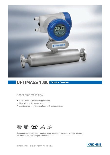
<strong>OPTIMASS</strong> <strong>1000</strong> Technical DatasheetSensor for mass <strong>flow</strong>• First choice for universal applications• Best price-performance ratio• A wide range of options available with no restrictionsThe documentation is only complete when used in combination with the relevantdocumentation for the signal converter.© KROHNE 03/2011 - 4000040304 - TD <strong>OPTIMASS</strong> <strong>1000</strong> R05 en
CONTENTS<strong>OPTIMASS</strong> <strong>1000</strong>1 Product features 31.1 Overview............................................................................................................................ 31.2 Features and options........................................................................................................ 51.3 Meter / converter combinations....................................................................................... 61.4 Measuring principle (twin tube) ....................................................................................... 62 Technical data 82.1 Technical data................................................................................................................... 82.2 Measuring accuracy ....................................................................................................... 142.3 Guidelines for maximum operating pressure................................................................ 152.4 Dimensions and weights ................................................................................................ 172.4.1 Flanged versions................................................................................................................... 172.4.2 Hygienic versions .................................................................................................................. 212.4.3 Heating jacket version .......................................................................................................... 252.4.4 Purge port option .................................................................................................................. 263 Installation 273.1 Intended use ................................................................................................................... 273.2 Mounting restrictions ..................................................................................................... 273.2.1 General installation principles ............................................................................................. 273.2.2 Sunshades............................................................................................................................. 293.2.3 Maximum pipework forces (end loadings) ........................................................................... 302 www.krohne.com 03/2011 - 4000040304 - TD <strong>OPTIMASS</strong> <strong>1000</strong> R05 en
<strong>OPTIMASS</strong> <strong>1000</strong>PRODUCT FEATURES 11.1 OverviewThe <strong>OPTIMASS</strong> <strong>1000</strong> is the cost effective solution for accurate measurement for a variety ofapplications. The <strong>OPTIMASS</strong> <strong>1000</strong> reliably measures mass<strong>flow</strong>, density, volume, temperature,volume concentration or solid content.1 Comprehensive diagnostic capabilities.2 Standard flange and hygienic process connections available.3 Twin straight measuring tubes plus secondary containment available.4 Standard electronics for all sensors with redundant storage of calibration and sensor data.5 Modular electronics with a range of output options (see separate documentation for details).1 Remote terminal box03/2011 - 4000040304 - TD <strong>OPTIMASS</strong> <strong>1000</strong> R05 enwww.krohne.com3
1 PRODUCT FEATURES<strong>OPTIMASS</strong> <strong>1000</strong>Highlights• Innovative twin measuring tubes• Easily drained and easy to clean• Resistant to installation and process effects• Long working life.• Optimised <strong>flow</strong> divider for minimum pressure loss.• High levels of accuracy means an excellent price / performance ratio.• Modular electronics with data redundancy - "plug & play" replacement of electronicsIndustries• Water & wastewater• Chemical• Food & beverage• Paper & pulp• Petrochemical industry• Pharmaceutical industryApplications• Suitable for all standard applications up to 130°C• Hygienic connections make it ideal for food / beverage applications.4www.krohne.com03/2011 - 4000040304 - TD <strong>OPTIMASS</strong> <strong>1000</strong> R05 en
<strong>OPTIMASS</strong> <strong>1000</strong>PRODUCT FEATURES 11.2 Features and optionsFeatures• Available as compact or remote.• Low pressure loss, guarantees a low pressuredrop across the meter.• Self Draining.• Easy to clean.Connection options• A range of flanges up to ASME 600 / PN100.• Supports a wide range of industry standardhygienic connections.• Adaptable to suit customer's hygienicconnections.Heating jacket & purge port• Heating jacket option for use with temperaturedependant products.• Prevents solidification of process product.• Purge port option for protection in the event ofmeasuring tube faliure.• Allows hazardous chemicals to be drained awaysafely.• Can also be used for the early detection ofmeasuring tube failure where highly toxicchemicals are being measured.03/2011 - 4000040304 - TD <strong>OPTIMASS</strong> <strong>1000</strong> R05 enwww.krohne.com5
1 PRODUCT FEATURES<strong>OPTIMASS</strong> <strong>1000</strong>1.3 Meter / converter combinationsConverter MFC 010 MFC 300Configuration Compact Compact Remote field Remote wall Remote rack<strong>OPTIMASS</strong> <strong>1000</strong> 1010C 1300C 1300F 1300W 1300R1.4 Measuring principle (twin tube)Static meter not energised and with no <strong>flow</strong>1 Measuring tubes2 Drive coil3 Sensor 14 Sensor 2A Coriolis twin tube mass <strong>flow</strong>meter consists of two measuring tubes 1 a drive coil 2 and twosensors (3 and 4) that are positioned either side of the drive coil.Energised meter1 Measuring tubes2 Direction of oscilation3 Sine waveWhen the meter is energised, the drive coil vibrates the measuring tubes causing them tooscillate and produce a sine wave 3. The sine wave is monitored by the two sensors.6www.krohne.com03/2011 - 4000040304 - TD <strong>OPTIMASS</strong> <strong>1000</strong> R05 en
<strong>OPTIMASS</strong> <strong>1000</strong>PRODUCT FEATURES 1Energised meter with process <strong>flow</strong>1 Process <strong>flow</strong>2 Sine wave3 Phase shiftWhen a fluid or gas passes through the tubes, the coriolis effect causes a phase shift in the sinewave that is detected by the two sensors. This phase shift is directly proportional to the mass<strong>flow</strong>.Density measurement is made by evaluation of the frequency of vibration and temperaturemeasurement is made using a Pt500 sensor.03/2011 - 4000040304 - TD <strong>OPTIMASS</strong> <strong>1000</strong> R05 enwww.krohne.com7
2 TECHNICAL DATA<strong>OPTIMASS</strong> <strong>1000</strong>2.1 Technical data• The following data is provided for general applications. If you require data that is morerelevant to your specific application, please contact us or your local representative.• Additional information (certificates, special tools, software,...) and complete productdocumentation can be downloaded free of charge from the website (Download Center).Measuring systemMeasuring principleApplication rangeMeasured valuesCalculated valuesCoriolis mass <strong>flow</strong><strong>Mass</strong> <strong>flow</strong> and density measurement of fluids, gases and solids<strong>Mass</strong>, density, temperatureVolume, referred density, concentration, velocityDesignBasicFeaturesVariantsCompact versionRemote versionModbus versionSystem consists of a measuring sensor and a converter to process theoutput signalFully welded maintenance free sensor with twin straight measuring tubesIntegral converterAvailable with field, wall or 19" rack mount versions of the converterSensor with integral electronics providing Modbus output for connection to aPLCMeasuring accuracy<strong>Mass</strong>Liquid±0.15% of actual measured <strong>flow</strong> rate + zero stabilityGas±0.5% of actual measured <strong>flow</strong> rate + zero stabilityRepeatabilityBetter than 0.05% plus zero stability (includes the combined effects ofrepeatability, linearity and hysteresis)Zero stabilityStainless Steel±0.01% of maximum <strong>flow</strong> rate with respective sensor sizeReference conditionsProductWaterTemperature 20°C / 68°FOperating pressure1 barg / 14.5 psigEffect on sensor zero point caused by a shift in process temperatureStainless Steel 0.001% per 1°C / 0.00055% per 1°FEffect on sensor zero point caused by a shift in process pressureStainless Steel0.00012% of the max <strong>flow</strong> rate per 1 bar rel . / 0.0000083% of the max <strong>flow</strong> rateper 1 psigDensityMeasuring range 400...2500 kg/m 3 / 25...155 lbs/ft 3Accuracy ±2 kg/m 3 / ±0.13 lbs/ft 3 (S15: ±5 kg/m 3 / ±0.33 lbs/ft 3 )On site calibration ±0.5 kg/m 3 / ±0.033 lbs/ft 38www.krohne.com03/2011 - 4000040304 - TD <strong>OPTIMASS</strong> <strong>1000</strong> R05 en
<strong>OPTIMASS</strong> <strong>1000</strong>TECHNICAL DATA 2TemperatureAccuracy±1°C / 1.8°FOperating conditionsMaximum <strong>flow</strong> ratesS15S25S40S50Ambient temperatureCompact version with AluminiumconverterCompact version with Stainless SteelconverterRemote versionsProcess temperatureFlanged connectionHygienic connectionNominal pressure at 20°C / 68°FMeasuring tubeStainless SteelOuter cylinder6500 kg/h / 240 lbs/min27000 kg/h / 990 lbs/min80000 kg/h / 2935 lbs/min170000 kg/h / 6235 lbs/min-40...+60°C / -40…+140°FExtended temperature range: +65°C / +149°F for some I/O options. For moreinformation contact manufacturer.-40...+55°C / -40…+130°F-40...+65°C / -40…+149°F-40…+130°C / -40…+266°F-40…+130°C / -40…+266°F-1…100 barg / -14.5…1450 psigNon PED / CRN approved Typical burst pressure > 100 barg / 1450 psig at 20°CPED / CRN approved secondary-1…63 barg / -14.5…910 psigcontainmentPED approved secondary containment -1…100 barg / -14.5…1450 psigFluid propertiesPermissible physical conditionLiquids, gases, slurriesPermissible gas content (volume) Contact manufacturer for informationPermissible solid content (volume) Contact manufacturer for informationProtection category (acc. to EN 60529) IP 67, NEMA 4XInstallation conditionsInlet runsOutlet runsNone requiredNone requiredMaterialsMeasuring tube Stainless Steel UNS S31803 (1.4462)SpigotStainless Steel 316 / 316L (CF3M / 1.4409) dual certifiedFlangesStainless Steel 316 / 316L (1.4401 / 1.4404) dual certifiedOuter cylinderStainless Steel 304 / 304L (1.4301 / 1.4307) dual certifiedOptional Stainless Steel 316 / 316L (1.4401 / 1.4404) dual certifiedHeating jacket versionHeating jacket Stainless Steel 316L (1.4404)The outer cylinder is in contact with the heating medium03/2011 - 4000040304 - TD <strong>OPTIMASS</strong> <strong>1000</strong> R05 enwww.krohne.com9
2 TECHNICAL DATA<strong>OPTIMASS</strong> <strong>1000</strong>All versionsSensor electronics housing Stainless Steel 316L (1.4409)Junction box (remote version)Die cast Aluminium (polyurethane coating)Optional Stainless Steel 316 (1.4401)Process connectionsFlangeDINDN15…80 / PN40…100ASME ½…3" / ASME 150…600JIS15…80A / 10...20KHygienicTri-clover1…3"Tri-clamp DIN 32676DN25…80Tri-clamp ISO 28521…3"DIN 11864-2 Form ADN25…80Male thread DIN 11851DN25...80Male thread SMS 1...3"Male thread IDF / ISS 1...3"Male thread RJT 1...3"Electrical connectionsElectrical connectionsI/OFor full details, including: power supply, power consumption etc., seetechnical data for the relevant converterFor full details of I/O options, including data streams and protocols, seetechnical data for the relevant converterApprovals and certificationsMechanicalElectromagnetic compatibility (EMC) Namur NE 21/5.95acc. to CE89/336/EEC (EMC)72/73/EEC (Low Voltage Directive)European Pressure Equipment Directive PED 97-23 EC (acc. to AD 2000 Regelwerk)Factory Mutual / CSAClass I, Div 1 groups A, B, C, DClass II, Div 1 groups E, F, GClass III, Div 1 hazardous areasClass I, Div 2 groups A, B, C, DClass II, Div 2 groups F, GClass III, Div 2 hazardous areasANSI / CSA (Dual Seal) 12.27.901-2003Hygienic 3A 28-0310www.krohne.com03/2011 - 4000040304 - TD <strong>OPTIMASS</strong> <strong>1000</strong> R05 en
<strong>OPTIMASS</strong> <strong>1000</strong>TECHNICAL DATA 2ATEX (acc. 94/9/EC)<strong>OPTIMASS</strong> 1300C non Ex i Signal outputs without heating jacket / insulationEx d connection compartmentEx e connection compartmentII 2 G Ex d [ib] IIC T4....T1Optional: II 2 G Ex d [ib] IIC T6....T1II 2 D Ex tD A21 IP6x T185°COptional: II 2 D Ex tD A21 IP6x T160°CII 2 G Ex de [ib] IIC T4....T1Optional: II 2 G Ex de [ib] IIC T6....T1II 2 D Ex tD A21 IP6x T185°COptional: II 2 D Ex tD A21 IP6x T160°C<strong>OPTIMASS</strong> 1300C non Ex i signal outputs with heating jacket / insulationEx d connection compartmentEx e connection compartmentII 2 G Ex d [ib] IIC T4....T1Optional: II 2 G Ex d [ib] IIC T6....T1II 2 D Ex tD A21 IP6x T195°COptional: II 2 D Ex tD A21 IP6x T165°CII 2 G Ex de [ib] IIC T4....T1Optional: II 2 G Ex de [ib] IIC T6....T1II 2 D Ex tD A21 IP6x T195°COptional: II 2 D Ex tD A21 IP6x T165°C<strong>OPTIMASS</strong> 1300C Ex i signal outputs without heating jacket / insulationEx d connection compartmentEx e connection compartmentII 2(1) G Ex d [ia/ib] IIC T4....T1Optional: II 2(1) G Ex d [ia/ib] IIC T6....T1II 2(1) D Ex tD [iaD] A21 IP6x T185°COptional: II 2(1) D Ex tD [iaD] A21 IP6x T160°CII 2(1) G Ex de [ia/ib] IIC T4....T1Optional: II 2(1) G Ex de [ia/ib] IIC T6....T1II 2(1) D Ex tD [iaD] A21 IP6x T185°COptional: II 2(1) D Ex tD [iaD] A21 IP6x T160°C<strong>OPTIMASS</strong> 1300C Ex i signal outputs with heating jacket / insulationEx d connection compartmentEx e connection compartment<strong>OPTIMASS</strong> <strong>1000</strong> / 1010C without heating/ insulationII 2(1) G Ex d [ia/ib] IIC T4....T1Optional: II 2(1) G Ex d [ia/ib] IIC T6....T1II 2(1) D Ex tD [iaD] A21 IP6x T195°COptional: II 2(1) D Ex tD [iaD] A21 IP6x T165°CII 2(1) G Ex de [ia/ib] IIC T4....T1Optional: II 2(1) G Ex de [ia/ib] IIC T6....T1II 2(1) D Ex tD [iaD] A21 IP6x T195°COptional: II 2(1) D Ex tD [iaD] A21 IP6x T165°CII 2 G Ex ib IIC T4…T1Optional: II 2 G Ex ib IIC T6…T1II 2 D Ex ibD 21 T175 °COptional: II 2 D Ex ibD 21 T165 °C03/2011 - 4000040304 - TD <strong>OPTIMASS</strong> <strong>1000</strong> R05 enwww.krohne.com11
2 TECHNICAL DATA<strong>OPTIMASS</strong> <strong>1000</strong><strong>OPTIMASS</strong> <strong>1000</strong> / 1010C with heating /insulationII 2 G Ex ib IIC T4…T1Optional: II 2 G Ex ib IIC T6…T1II 2 D Ex ibD 21 T175 °COptional: II 2 D Ex ibD 21 T165 °CATEX (acc. 94/9/EC) temperature limits (standard)<strong>OPTIMASS</strong> <strong>1000</strong> / 1010C - with orwithout heating jacket / insulation<strong>OPTIMASS</strong> 1300C - aluminium converterhousing - no heating jacket / insulation<strong>OPTIMASS</strong> 1300C- aluminium converterhousing - heating jacket / insulation<strong>OPTIMASS</strong> 1300C - SS converter housing- no heating jacket / insulation<strong>OPTIMASS</strong> 1300C - SS converter housing- heating jacket / insulationAmbient temp.Tamb °C1 depending on I/O option. Please call for more information.ATEX (acc. 94/9/EC) temperature limits (T6)Max. mediumtemp. Tm °CTemp. class65 89 T4 T130130 T3 - T1 T17550 70 T4 T130130 T3 - T1 T18560 60 T4 - T1 T12565 1 65 T4 - T1 T13040 65 T4 T130130 T3 - T1 T19550 65 T4 T130100 T3 - T1 T16560 60 T4 - T1 T12565 1 65 T4 - T1 T13050 70 T4 T130130 T3 - T1 T18555 55 T4 - T1 T12040 65 T4 T130120 T3 - T1 T18550 65 T4 T13075 T3 - T1 T14055 55 T4 - T1 T120Max. surfacetemp. °C<strong>OPTIMASS</strong> <strong>1000</strong> / 1010C T6 - with orwithout heating jacket / insulationAmbient temp.Tamb °CMax. mediumtemp. Tm °CTemp. class40 45 T6 T8060 T5 T9595 T4 T130130 T3 – T1 T16550 60 T5 T9595 T4 T130130 T3 – T1 T16565 95 T4 T130130 T3 – T1 T165Max. surfacetemp. °C12www.krohne.com03/2011 - 4000040304 - TD <strong>OPTIMASS</strong> <strong>1000</strong> R05 en
<strong>OPTIMASS</strong> <strong>1000</strong>TECHNICAL DATA 2<strong>OPTIMASS</strong> 1300C T6 - aluminiumconverter housing - no heating jacket /insulation<strong>OPTIMASS</strong> 1300C T6 - aluminiumconverter housing - heating jacket /insulation<strong>OPTIMASS</strong> 1300C T6 - Stainless Steelconverter housing - no heating jacket /insulation<strong>OPTIMASS</strong> 1300C T6 - Stainless Steelconverter housing - heating jacket /insulationAmbient temp.Tamb °C1 depending on I/O option. Please call for more information.Max. mediumtemp. Tm °CTemp. class40 45 T6 T8060 T5 T95100 T4 T130130 T3 - T1 T15550 60 T5 T95100 T4 T130130 T3 - T1 T16060 60 T4 - T1 T9565 1 65 T4 - T1 T10040 45 T6 T8060 T5 T9595 T4 T130130 T3 - T1 T16550 60 T5 T9595 T4 T130100 T3 - T1 T13560 60 T4 - T1 T9565 1 65 T4 - T1 T10040 45 T6 T8060 T5 T95100 T4 T130130 T3 - T1 T15550 60 T5 T95100 T4 T130130 T3 - T1 T16055 55 T4 - T1 T9540 45 T6 T8060 T5 T9595 T4 T130120 T3 - T1 T15550 60 T5 T9575 T4 - T1 T11055 55 T4 - T1 T130Max. surfacetemp. °C03/2011 - 4000040304 - TD <strong>OPTIMASS</strong> <strong>1000</strong> R05 enwww.krohne.com13
2 TECHNICAL DATA<strong>OPTIMASS</strong> <strong>1000</strong>2.2 Measuring accuracy1.61.41.21.00.80.60.40.20X <strong>flow</strong> rate [%]Y measuring error [%]Measuring errorThe measuring error is obtained from the combined effects of accuracy and zero stability.Reference conditionsProductTemperatureOperating pressureWater+20°C / +68°F1 barg / 14.5 psig14www.krohne.com03/2011 - 4000040304 - TD <strong>OPTIMASS</strong> <strong>1000</strong> R05 en
<strong>OPTIMASS</strong> <strong>1000</strong>TECHNICAL DATA 22.3 Guidelines for maximum operating pressureNotes:• Ensure that the meter is used within its operating limits• All hygienic process connections have a maximum operating rating of 10 barg at 130°C / 145psig at 266°FPressure / temperature de-rating, all meter sizes, in metric (flanged connections asper EN 1092-1)X temperature [°C]Y pressure [barg]1 Measuring tubes and 100barg 316L secondary containment (PED)2 63 barg 304L / 316 secondary containment (PED)03/2011 - 4000040304 - TD <strong>OPTIMASS</strong> <strong>1000</strong> R05 enwww.krohne.com15
2 TECHNICAL DATA<strong>OPTIMASS</strong> <strong>1000</strong>Pressure / temperature de-rating, all meter sizes, in imperial (flanged connections asper ASME B16.5)X temperature [°F]Y pressure [psig]1 Measuring tubes S15 / S25 (CRN)2 Measuring tubes S40 (CRN)3 Measuring tubes S50 (CRN)4 Secondary containment 304L / 316L (CRN)Flanges• DIN flange ratings are based on EN 1092-1 2001 table 18 (1% proof stress) material group14EO• ASME flange ratings are based on ASME B16.5 2003 table 2 material group 2.2• JIS flange ratings are based on JIS 2220: 2001 table 1 division 1 material group 022aNotes• The maximum operating pressure will be either the flange rating or the measuring tuberating, WHICHEVER IS THE LOWER!• The manufacturer recommends that the seals are replaced at regular intervals. This willmaintain the hygienic integrity of the connection.16www.krohne.com03/2011 - 4000040304 - TD <strong>OPTIMASS</strong> <strong>1000</strong> R05 en
<strong>OPTIMASS</strong> <strong>1000</strong>TECHNICAL DATA 22.4 Dimensions and weights2.4.1 Flanged versions1EC1DAH2BFGEC2DAC2HB1 Compact version2 Remote versionMeter weights (all flanges)Weight [kg]S15 S25 S40 S50Aluminium (compact) 13.5 16.5 29.5 57.5Stainless Steel (compact) 18.8 21.8 34.8 62.8Aluminium (remote) 11.5 14.5 25.5 51.5Stainless Steel (remote) 12.4 15.4 26.4 52.4Weight [lbs]S15 S25 S40 S50Aluminium (compact) 30 36.3 65 127Stainless Steel (compact) 41 48 77 138Aluminium (remote) 25 32 56 113Stainless Steel (remote) 27 33.8 58 11503/2011 - 4000040304 - TD <strong>OPTIMASS</strong> <strong>1000</strong> R05 enwww.krohne.com17
2 TECHNICAL DATA<strong>OPTIMASS</strong> <strong>1000</strong>Measuring tube in Stainless SteelDimensions [mm]S15 S25 S40 S50A 101.6 114.3 168.3 219.1C1 (compact) 311 317 344 370C2 (remote) 231 237 264 290D 160E 60F 123.5G 137H 98.5Dimensions [inches]S15 S25 S40 S50A 4 4.5 6.6 8.6C1 (compact) 12.2 12.5 13.5 14.6C2 (remote) 9 9.3 10.4 11.4D 6.3E 2.4F 4.9G 5.4H 3.9Flange connectionsDimension B [mm]S15 S25 S40 S50PN40DN15 498 - - -DN25 503 531 - -DN40 513 541 706 -DN50 - 547 712 862DN80 - - 732 882DN100 - - - 896PN63DN50 - - 740 890DN80 - - - 910PN100DN15 513 - - -DN25 538 567 - -DN40 - 575 740 -DN50 - - 752 902DN80 - - - 92218www.krohne.com03/2011 - 4000040304 - TD <strong>OPTIMASS</strong> <strong>1000</strong> R05 en
<strong>OPTIMASS</strong> <strong>1000</strong>TECHNICAL DATA 2ASME 150½¨ 518 - - -¾¨ 528 - - -1¨ 534 563 - -1½¨ - 575 740 -2¨ - 579 744 8943¨ - - 756 9064¨ - - - 920ASME 300½¨ 528 - - -¾¨ 538 - - -1¨ 546 575 - -1½¨ - 589 754 -2¨ - - 756 9063¨ - - - 926ASME 600½¨ 541 - - -¾¨ 550 - - -1¨ 558 589 - -1½¨ - 603 770 -2¨ - - 774 9263¨ - - - 944JIS 10K50A - - 712 86280A - - - 882JIS 20K15A 498 - - -25A 503 531 - -40A - 541 706 -50A - - 712 86280A - - - 882Dimension B [inches]S15 S25 S40 S50PN40DN15 19.6 - - -DN25 19.8 21 - -DN40 20.2 21.3 27.8 -DN50 - 21.5 28 33.9DN80 - - 28.8 34.7DN100 - - - 35.303/2011 - 4000040304 - TD <strong>OPTIMASS</strong> <strong>1000</strong> R05 enwww.krohne.com19
2 TECHNICAL DATA<strong>OPTIMASS</strong> <strong>1000</strong>PN63DN50 - - 29 35DN80 - - - 35.8PN100DN15 20.2 - - -DN25 21.2 22.3 - -DN40 - 22.6 29 -DN50 - - 29.6 35.5DN80 - - - 36.3ASME 150½¨ 20.4 - - -¾¨ 20.8 - - -1¨ 21 22.2 - -1½¨ - 22.5 29.1 -2¨ - 22.8 29.3 35.23¨ - - 29.8 35.74¨ - - - 36.2ASME 300½¨ 20.8 - - -¾¨ 21.2 - - -1¨ 21.5 22.6 - -1½¨ - 23.2 29.7 -2¨ - - 29.8 35.73¨ - - - 36.4ASME 600½¨ 21.3 - - -¾¨ 21.6 - - -1¨ 22 23.2 - -1½¨ - 23.7 30.3 -2¨ - - 30.5 36.43¨ - - - 37.2JIS 10K50A - - 28 33.980A - - - 34.7JIS 20K15A 19.6 - - -25A 19.8 20.9 - -40A - 21.3 27.8 -50A - - 28 33.980A - - - 34.720www.krohne.com03/2011 - 4000040304 - TD <strong>OPTIMASS</strong> <strong>1000</strong> R05 en
<strong>OPTIMASS</strong> <strong>1000</strong>TECHNICAL DATA 22.4.2 Hygienic versionsHygienic connections: all welded versionsDimension B [mm]S15 S25 S40 S50Tri-clover1" 487 - - -1½" - 534 - -2" - - 691 -3" - - - 832Tri-clamp DIN 32676DN10 - - - -DN15 - - - -DN25 468 - - -DN40 - 515 - -DN50 - - 677 -DN80 - - - 836Tri-clamp ISO 28521" 473 - - -1½" - 502 - -2" - - 667 -3" - - - 817DIN 11864-2 form ADN25 505 - - -DN40 - 562 - -DN50 - - 724 -DN80 - - - 89603/2011 - 4000040304 - TD <strong>OPTIMASS</strong> <strong>1000</strong> R05 enwww.krohne.com21
2 TECHNICAL DATA<strong>OPTIMASS</strong> <strong>1000</strong>Dimension B [inches]S15 S25 S40 S50Tri-clover1" 19.2 - - -1½" - 21 - -2" - - 27.2 -3" - - - 32.7Tri-clamp DIN 32676DN10 - - - -DN15 - - - -DN25 18.4 - - -DN40 - 20.3 - -DN50 - - 26.6 -DN80 - - - 32.9Tri-clamp ISO 28521" 18.6 - - -1½" - 19.8 - -2" - - 26.3 -3" - - - 32.2DIN 11864-2 form ADN25 19.9 - - -DN40 - 22.2 - -DN50 - - 28.5 -DN80 - - - 35.322www.krohne.com03/2011 - 4000040304 - TD <strong>OPTIMASS</strong> <strong>1000</strong> R05 en
<strong>OPTIMASS</strong> <strong>1000</strong>TECHNICAL DATA 2Hygienic connections: adapter versions (male thread)Dimension B [mm]S15 S25 S40 S50Male thread DIN 11851DN25 483 - - -DN40 - 538 - -DN50 - - 704 -DN80 - - - 870Male thread SMS1" 474 - - -1½" - 537 - -2" - - 694 -3" - - - 837Male thread IDF/ISS1" 487 - - -1½" - 534 - -2" - - 691 -3" - - - 832Male thread RJT1" 498 - - -1½" - 545 - -2" - - 702 -3" - - - 84303/2011 - 4000040304 - TD <strong>OPTIMASS</strong> <strong>1000</strong> R05 enwww.krohne.com23
2 TECHNICAL DATA<strong>OPTIMASS</strong> <strong>1000</strong>Dimension B [inches]S15 S25 S40 S50Male thread DIN 11851DN25 19 - - -DN40 - 21.2 - -DN50 - - 27.7 -DN80 - - - 34.2Male thread SMS1" 18.7 - - -1½" - 21.1 - -2" - - 27.3 -3" - - - 32.9Male thread IDF/ISS1" 19.2 - - -1½" - 21 - -2" - - 27.2 -3" - - - 32.7Male thread RJT1" 19.6 - - -1½" - 21.4 - -2" - - 27.6 -3" - - - 33.224www.krohne.com03/2011 - 4000040304 - TD <strong>OPTIMASS</strong> <strong>1000</strong> R05 en
<strong>OPTIMASS</strong> <strong>1000</strong>TECHNICAL DATA 22.4.3 Heating jacket versionDimensions [mm]S15 S25 S40 S50Heating connection size 12 mm (ERMETO) 25A 115 ±1 142 ±1 206 ±1 254 ±1B 51 55 90 105C 20 26Dimensions [inches]S15 S25 S40 S50Heating connection size ½" (NPTF) 1A 4.5 ±0.04 5.6 ±0.04 8.1 ±0.04 10 ±0.04B 2.0 2.2 3.5 4.1C 0.8 1.003/2011 - 4000040304 - TD <strong>OPTIMASS</strong> <strong>1000</strong> R05 enwww.krohne.com25
2 TECHNICAL DATA<strong>OPTIMASS</strong> <strong>1000</strong>2.4.4 Purge port optionDimensions [mm]S15 S25 S40 S50A 55 ±1.0 65 ±1.0B 55 ±1.0 65 ±1.0Dimensions [inches]S15 S25 S40 S50A 2.2 ±0.04 2.5 ±0.04B 2.2 ±0.04 2.5 ±0.0426www.krohne.com03/2011 - 4000040304 - TD <strong>OPTIMASS</strong> <strong>1000</strong> R05 en
<strong>OPTIMASS</strong> <strong>1000</strong>INSTALLATION 33.1 Intended useThis mass <strong>flow</strong>meter is designed for the direct measurement of mass <strong>flow</strong> rate, product densityand product temperature. Indirectly, it also enables the measurement of para<strong>meters</strong> like totalmass, concentration of dissolved substances and the volume <strong>flow</strong>. For use in hazardous areas,special codes and regulations are also applicable and these are specified in a separatedocumentation.3.2 Mounting restrictions3.2.1 General installation principlesThere are no special installation requirements but you should note the followingpoints:• Support the weight of the meter.• The meter can be supported on the sensor body.• On larger meter sizes and hygienic connections, it is strongly recommended that the meter isnot supported solely by the process pipework.• No straight runs are required.• The use of reducers and other fittings at flanges, including flexible hoses, is allowed but youshould take care to avoid cavitation.• Avoid extreme pipe size reductions.• Meters are not affected by crosstalk and can be mounted in series or in parallel.• Avoid mounting the meter at the highest point in the pipeline where air / gas can collect.03/2011 - 4000040304 - TD <strong>OPTIMASS</strong> <strong>1000</strong> R05 enwww.krohne.com27
3 INSTALLATION<strong>OPTIMASS</strong> <strong>1000</strong>Mounting positions1 The meter can be mounted at an angle but it is recommended that the <strong>flow</strong> is uphill.2 Avoid mounting the meter with the <strong>flow</strong> running downhill because it can cause siphoning. If the meter has to be mountedwith the <strong>flow</strong> running downhill, install an orifice plate or control valve downstream of the meter to maintain backpressure.3 Horizontal mounting with <strong>flow</strong> running left to right.4 Avoid mounting meter with long vertical runs after the meter as it can cause cavitation. Where the installation includesa vertical run after the meter, install an orifice plate or control valve downstream to maintain backpressure.5 The meter can be mounted vertically but it is recommended that the <strong>flow</strong> is uphill.6 Avoid mounting the meter vertically with the <strong>flow</strong> running downhill. This can cause siphoning. If the meter has to beinstalled this way, install an orifice plate or control valve downstream to maintain backpressure.28www.krohne.com03/2011 - 4000040304 - TD <strong>OPTIMASS</strong> <strong>1000</strong> R05 en
<strong>OPTIMASS</strong> <strong>1000</strong>INSTALLATION 3Zero calibration3.2.2 Sunshades1 Where the meter has been installed vertically, install shut-off valves either side of the meter to assist with zero calibration.2 If the process <strong>flow</strong> cannot be stopped, install a bypass section for zero calibration.The meter MUST be protected from strong sunlight.1 Horizontal installation2 Vertical installation03/2011 - 4000040304 - TD <strong>OPTIMASS</strong> <strong>1000</strong> R05 enwww.krohne.com29
3 INSTALLATION<strong>OPTIMASS</strong> <strong>1000</strong>3.2.3 Maximum pipework forces (end loadings)<strong>Mass</strong> <strong>flow</strong><strong>meters</strong> have a maximum level of force (negative or positive) that can be applied to theends of the meter. Refer to the table below for permitted forces.Maximum end loadingsS15 S25 S40 S50Flanges20°C 40 barg 25kN 38kN 48kN 99kN100 barg 17kN 19kN 15kN 20kN130°C 32 barg 18kN 28kN 35kN 72kN80 barg 12kN 12kN 7kN 8kNHygienic (all connections)130°C 10 barg 5kN 9kN 12kN 12kN• These (axial) loads have been calculated, based on 316L schedule 40 process pipework,where un-radiographed butt welds have been used in pipe joints.• The loads shown are the maximum permitted static load. If loads are cycling (betweentension and compression) these loads should be reduced. For advice, consult themanufacturer.30www.krohne.com03/2011 - 4000040304 - TD <strong>OPTIMASS</strong> <strong>1000</strong> R05 en
<strong>OPTIMASS</strong> <strong>1000</strong>403/2011 - 4000040304 - TD <strong>OPTIMASS</strong> <strong>1000</strong> R05 enwww.krohne.com31
KKKKROHNE product overview© KROHNE 03/2011 - 4000040304 - TD <strong>OPTIMASS</strong> <strong>1000</strong> R05 en - Subject to change without notice.• Electromagnetic <strong>flow</strong><strong>meters</strong>• Variable area <strong>flow</strong><strong>meters</strong>• Ultrasonic <strong>flow</strong><strong>meters</strong>• <strong>Mass</strong> <strong>flow</strong><strong>meters</strong>• Vortex <strong>flow</strong><strong>meters</strong>• Flow controllers• Level <strong>meters</strong>• Temperature <strong>meters</strong>• Pressure <strong>meters</strong>• Analysis products• Measuring systems for the oil and gas industry• Measuring systems for sea-going tankersHead Office KROHNE Messtechnik GmbHLudwig-Krohne-Str. 5D-47058 Duisburg (Germany)Tel.:+49 (0)203 301 0Fax:+49 (0)203 301 10389info@krohne.deThe current list of all KROHNE contacts and addresses can be found at:www.krohne.com