Radial Diaphragm Valve, DR Series (MS-02-186;rev_4 ... - Swagelok
Radial Diaphragm Valve, DR Series (MS-02-186;rev_4 ... - Swagelok
Radial Diaphragm Valve, DR Series (MS-02-186;rev_4 ... - Swagelok

You also want an ePaper? Increase the reach of your titles
YUMPU automatically turns print PDFs into web optimized ePapers that Google loves.
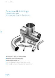
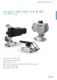
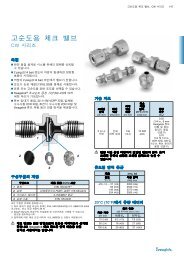
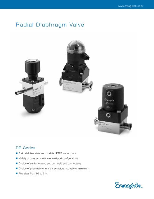
www.swagelok.com<strong>Radial</strong> <strong>Diaphragm</strong> <strong>Valve</strong><strong>DR</strong> <strong>Series</strong>■ 316L stainless steel and modified PTFE wetted parts■ Variety of compact multivalve, multiport configurations■ Choice of sanitary clamp and butt weld end connections■ Choice of pneumatic or manual actuators in plastic or aluminum■ Five sizes from 1/2 to 2 in.
2 <strong>Radial</strong> <strong>Diaphragm</strong> <strong>Valve</strong>sContentsFeatures ........................................ 2<strong>DR</strong> <strong>Series</strong> versus Weir Style ........................ 3Standard One-<strong>Valve</strong> Configurations .................. 4Standard Two-<strong>Valve</strong> Configurations .................. 5Typical Body Dimensions .......................... 6Technical Data ................................... 7Flow Data ...................................... 7Testing ......................................... 7Cleaning and Packaging .......................... 7Inspection ..................................... 7Validation Documentation ......................... 7Plastic Actuators ................................ 8Aluminum Actuators ............................. 10Point-of-Use <strong>Valve</strong>s ............................. 12Ordering Information ............................. 14Position Indicator Switch Assemblies ................ 15The <strong>Swagelok</strong> ® <strong>DR</strong> series radial diaphragm valve offers acleaner, more compact way to manage sterile flow streams.The <strong>DR</strong> series valve minimizes entrapment areas, drains easily,maximizes cleanability, and provides extended diaphragm life.It provides a clean solution for many applications includingmedia preparation, fermentation, harvest, separation, refining,purification, CIP, and SIP systems.FeaturesMultivalve and MultiportConfigurations■ Reduce overall system size■ Provide instantaneous flow shifts,reducing the potential for crosscontamination■ Require fewer fittings and pipingand less welding, making the systemeasier to validate■ Reduce or eliminate dead legs.The single-body design can be manufactured in a wide rangeof configurations to include multiple valves and multiple ports,and point-of-use valves. A single <strong>Swagelok</strong> radial diaphragmvalve can replace complex weir-style valve assemblies,resulting in a more compact system.The <strong>DR</strong> series valve is designed for system pressures up to150 psig (10.3 bar) and operating temperatures up to 280°F(137°C).Extended <strong>Diaphragm</strong> Life■ Optimized diaphragm shapeminimizes stresses during cycling■ Uniformly distributed shutoff forceminimizes diaphragm distortion■ Modified PTFE diaphragm materialimproves thermal cycling performancePneumatic Actuators■ Choice of normally closed, normallyopen, and double-acting modes ofactuation■ Are offered in plastic or aluminum■ Are available with an optionalposition indicator switch assembly.Manual Actuators■ Feature a knob handle for 1/2, 3/4,and 1 in. sizes, and a hand wheel for1 1/2, and 2 in. sizes■ Provide positive shutoff with minimaltorque■ Open valve fully in 1 to 1 1/2 turns■ Are offered in plastic or aluminum.Live-Loaded <strong>Diaphragm</strong> ➀■ Controls cold flow of the modifiedPTFE diaphragm■ Maintains seal to body during thermalcyclingShown with pneumatic plastic actuator➀ 1/2 in. model maintains a seal without a liveloadeddiaphragm
<strong>Radial</strong> <strong>Diaphragm</strong> <strong>Valve</strong>s 3<strong>DR</strong> <strong>Series</strong> versus Weir Style<strong>DR</strong> <strong>Series</strong> <strong>Valve</strong>■ Reduced entrapmentThe geometry at the pointof the seal between thediaphragm and the valvebody creates a line sealand minimizes entrapmentareas.Weir-Style <strong>Valve</strong>■ Fluid entrapment areaThe seal between thediaphragm and valve bodyis made outside of the bowlrim, creating the potentialfor entrapment.No flexing at the pointof seal sustains the sealintegrity during cyclingFlexing at the point of sealduring cycling■ <strong>Diaphragm</strong> containmentThe outer diameter of the diaphragm is contained bya counterbore in the valve body. This design controlsextrusion and sustains seal integrity during thermal cycling.■ Body bowl geometryThe rounded, open bowl enhances cleaning.<strong>DR</strong> <strong>Series</strong> <strong>Valve</strong>Line seal maintained during cycling of valve. No entrapmentareas created.ClosedWeir-Style <strong>Valve</strong>During cycling, flexing of the diaphragm at the point of sealcreates a potential area of entrapment.ClosedPoint of sealPoint of sealOpenOpenLine sealmaintainedPotentialentrapment area
4 <strong>Radial</strong> <strong>Diaphragm</strong> <strong>Valve</strong>sStandard One-<strong>Valve</strong> ConfigurationsBody StyleDesignatorExternalViewInternalViewSchematicDiagramDescription/Application4B Inlet1AstraightShutofftwo-wayvertical3A Outlet1Belbow to left1AOutlet4B InletShutofftwo-way elbowwith flowdown and to left1Celbow to right4B Inlet2AOutletShutofftwo-way elbowwith flowdown and to right1Eoffset flow to left1AOutlet2BInlet2B InletShutofftwo-way horizontalwith flow to left1Foffset flow to right1BInlet2AOutlet2A OutletShutofftwo-way horizontalwith flow to right1Gtee withoutlet to bottom1BThrough3A Outlet2BThrough2B Through1Kvertical elbow withoutlet to bottom1Nright elbow withoutlet to bottom3A Outlet3A Outlet4BThrough5BThrough5BThrough2BThrough■ Tee configuration■ Ideal for use aspoint-of-use, drainor sample port1Rleft elbow withoutlet to bottom1BThrough5BThrough3A OutletAll body configurations are shown in the most drainable position.<strong>Valve</strong>s may be used in the <strong>rev</strong>erse direction, but may not be fully drainable.Connections are marked with a 1, 2, 3, 4, or 5, followed by an A or B.(See diagram on page 14 for more information.) The letter A indicates anoutlet connection; B indicates an inlet connection.
Standard Two-<strong>Valve</strong> Configurations<strong>Radial</strong> <strong>Diaphragm</strong> <strong>Valve</strong>s 5Body StyleDesignatorExternalView4AOutletInternalViewSchematicDiagramDescription/Application2Acommon center2Bcommon left1BCommonInlet1BCommonInlet3A Outlet2AOutletIdeal for divertingwhere drainabilityis not critical3A Outlet2Coffset 90°,common left1BCommonInlet2AOutlet3A Outlet4B CommonInlet2Doffset 90°,common top2Eoffset sidecommon top1AOutlet2AOutlet3A Outlet4B CommonInlet2AOutlet■ Ideal for diverting■ <strong>Diaphragm</strong> closeson common portto control flow2Foffset horizontal1BCommonInlet2A2Outlet2Kmixing 90°common side2Lmixing 90°,common bottom1BInlet1BInlet2A1Outlet4BInlet2ACommonOutlet4BInlet■ Ideal for mixing■ Common portis outlet port3A CommonOutlet2Mmixing side,common bottom1BInlet2BInlet3A CommonOutletAll body configurations are shown in the most drainable position.<strong>Valve</strong>s may be used in the <strong>rev</strong>erse direction, but may not be fully drainable.Connections are marked with a 1, 2, 3, or 4, followed by an A or B.(See diagram on page 14 for more information.) The letter A indicates anoutlet connection; B indicates an inlet connection.
6 <strong>Radial</strong> <strong>Diaphragm</strong> <strong>Valve</strong>sTypical Body DimensionsDimensions are for reference only and are subject to change.1A BodyTypical1-valveconfigurationwith 2 portsEECAT 3 0.065 in.BShown with TB(tube butt weld) endsBodyStyle1A<strong>Valve</strong>Sizein.1/23/411 1/22A B C2.00(50.8)3.00(76.2)4.00(1<strong>02</strong>)5.18(132)6.00(152)1.13(28.7)1.44(36.6)2.00(50.8)2.56(65.0)3.19(81.0)Dimensions, in. (mm)0.50(12.7)0.62(15.7)0.81(20.6)1.00(25.4)1.32(33.5)BodyWeightlb (kg)➀ TB = tube butt weld ends; SC = TS series and Kwik-Clamp sanitary clampend connections.ETB➀ SC➀2.50(63.5)3.00(76.2)3.50(88.9)4.25(108)4.75(121)1.75(44.4)2.50(63.5)3.25(82.6)4.25(108)4.75(121)T0.50(12.7)0.75(19.1)1.00(25.4)1.50(38.1)2.00(50.8)1.1(0.5)3.1(1.4)7.5(3.4)15.2(6.9)24.9(11.3)1G BodyTypical1-valveconfigurationwith 3 portsE 1ECDAT 3 0.065 in.BBodyStyle1G<strong>Valve</strong>Sizein.1/23/411 1/2A B C2.00(50.8)3.00(76.2)4.00(1<strong>02</strong>)5.18(132)1.13(28.7)1.44(36.6)2.00(50.8)2.56(65.0)0.50(12.7)0.62(15.7)0.81(20.6)1.00(25.4)Dimensions, in. (mm)DE1TB➀ SC➀ E TB➀ SC➀ T5.00(127)6.00(152)7.00(178)8.50(216)3.50(88.9)5.00(127)6.50(165)8.50(216)1.00(25.4)1.50(38.1)2.00(50.8)2.59(65.8)2.50(63.5)3.00(76.2)3.50(88.9)4.25(108)1.75(44.4)2.50(63.5)3.25(82.6)4.25(108)0.50(12.7)0.75(19.1)1.00(25.4)1.50(38.1)BodyWeightlb (kg)1.1(0.5)3.1(1.4)7.5(3.4)15.2(6.9)Shown with TB(tube butt weld) ends26.00(152)3.19(81.0)1.32(33.5)9.50(241)9.50(241)3.00(76.2)4.75(121)4.75(121)2.00(50.8)24.9(11.3)➀ TB = tube butt weld ends; SC = TS series and Kwik-Clamp sanitary clamp end connections.2C BodyTop viewE 1EDAFGBFront viewT 3 0.065 in.HCShown with SC (sanitary clamp fitting) endsTypical2-valveconfigurationwith 3 portsBodyStyle2C<strong>Valve</strong>Sizein.1/23/411 1/22A B C2.00(50.8)3.00(76.2)4.00(1<strong>02</strong>)5.18(132)6.00(152)1.75(44.4)2.50(63.5)3.50(88.9)4.63(118)6.00(152)0.50(12.7)0.62(15.7)0.81(20.6)1.00(25.4)1.32(33.5)Dimensions, in. (mm)DE 1TB➀ SC➀ E TB➀ SC➀ F G H T5.00(127)6.00(152)7.00(178)8.50(216)9.50(241)3.50(88.9)5.00(127)6.50(165)8.50(216)9.50(241)1.00(25.4)1.50(38.1)2.00(50.8)2.59(65.8)3.00(76.2)2.50(63.5)3.00(76.2)3.50(88.9)4.25(108)4.75(121)1.75(44.4)2.50(63.5)3.25(82.6)4.25(108)4.75(121)0.50(12.7)0.69(17.5)0.92(23.4)1.08(27.4)1.18(30.0)➀ TB = tube butt weld ends; SC = TS series and Kwik-Clamp sanitary clamp end connections.0.63(16.0)1.25(31.8)1.75(44.4)2.31(58.7)3.00(76.2)0.88(22.4)1.68(42.7)2.31(58.7)3.07(78.0)4.13(105)0.50(12.7)0.75(19.1)1.00(25.4)1.50(38.1)2.00(50.8)BodyWeightlb (kg)1.7(0.8)5.2(2.4)12.5(5.7)25.7(11.7)46.2(21.0)
<strong>Radial</strong> <strong>Diaphragm</strong> <strong>Valve</strong>s 7Technical Data<strong>Valve</strong> Pressure-Temperature RatingsFlow DataWaterTemperature°F (°C)14 (–10) to 190 (87)200 (93)250 (121)280 (137)Working Pressurepsig (bar)150 (10.3)138 (9.5)67 (4.6)40 (2.7)<strong>Valve</strong>Size1/2 in. 3/4 in.1 in.1 1/2 in.Water Flow, L/min2 in.Required Pressure Drop for <strong>Valve</strong>s withNormally Closed Pneumatic ActuatorsMinimum Pressure Drop, psiSystem Pressure, barSystem Pressure, psigMinimum Pressure Drop, barPressure drop, psiFlow CoefficientFlowCoefficientC vWater Flow, U.S. gal/min<strong>Valve</strong> Size, in.1/2 3/4 1 1 1/2 21.6 4.6 8.7 18.7 27.2Pressure drop, barActuator Pressure-Temperature RatingsMaterialAluminumPlasticTemperature Rating, °F (°C)Operating Ambient14 to 280°F(–10 to 137°C)Design SpecificationsAutoclavable to300°F (148°C) max190°F (89°C) maxWorkingPressurepsig (bar)70 to 120 psig(4.8 to 8.2 bar)70 to 100 psig(4.8 to 6.8 bar)The design and fabrication of <strong>Swagelok</strong> radial diaphragmvalves are in compliance with Part SD-4.6 Process(Hygienic) <strong>Valve</strong>s of ASME BPE.Material SpecificationsThe wetted components of <strong>Swagelok</strong> radial diaphragm valvesare traceable: valve bodies and fittings are heat traceable;diaphragm materials are lot traceable. All <strong>DR</strong> series valvebodies are machined from 316L stainless steel in accordancewith ASTM A479 specifications, providing integrity, strength,and high levels of purity.Surface Finish■ Interior body surfaces are electr opolished and finished to15 µin. (0.38 µm) R a max. All accessible welds are groundflush on the inside diameter.■ Exterior body surfaces are passivated and finished to63 µin. (1.60 µm) R a avg.TestingEvery <strong>Swagelok</strong> <strong>DR</strong> series radial diaphragm valve is inboardhelium leak tested to a maximum allowable leak rate of2.5 3 10 –3 std cm 3 /s, at the seat, envelope, and port welds,using FCI 70-2 as a guideline.Cleaning and PackagingAll <strong>Swagelok</strong> <strong>DR</strong> series radial diaphragm valves are cleanedand packaged in accordance with <strong>Swagelok</strong> StandardCleaning and Packaging (SC-10), <strong>MS</strong>-06-62.Inspection■ The interior surfaces of <strong>Swagelok</strong> <strong>DR</strong> series valve bodiesare 100 % visually inspected.■ All welds are performed by ASME Section IX certifiedwelders and are 100 % visually inspected.■ All completed valve assemblies are 100 % visuallyinspected prior to shipment.Validation DocumentationThe following validation documentation can be providedupon request:■ Certified mill test report on the valve body■ Certification of compliance to specifications■ Certification of compliance to 21CFR Part 177■ Quality Assurance Manual■ ISO 9001 certification
8 <strong>Radial</strong> <strong>Diaphragm</strong> <strong>Valve</strong>sPlastic ActuatorsFeatures■ Available for 1/2, 3/4, and 1 in. valves■ Choice of manual and pneumatic models■ Resistant to caustic washdownsPneumatic Models■ Choice of actuation modes: normally closed, normally open,or double acting■ Reliable piston-driven actuation■ Optional Westlock ® position indicator switch assemblyManual Models■ Open fully in one turn■ Positive shutoff with minimal torque ; no travel stop required.■ Visual indication of open position with rising handle button■ Low thermal conductivity of plastic handle providescomfortable operation in steam applications.1212334455Materials of ConstructionItemWetted components listed in italics.Material Grade/ASTM Specification1 Cap screws 304 SS2 Washers 304 SS3 ActuatorassemblyFDA-compliant polyethersulfone housing withFDA-compliant fluorocarbon FKM O-rings4 <strong>Diaphragm</strong> Modified PTFE/D48945 Body 316L SS/A479
Plastic ActuatorsManual ModelsFlow Coefficient at Turns Open<strong>Radial</strong> <strong>Diaphragm</strong> <strong>Valve</strong>s 9Ordering Information<strong>Valve</strong> with Plastic ActuatorTo order a complete valve with a plastic actuator, seeOrdering Information on page 14.Flow Coefficient (C v )3/4 in. <strong>Valve</strong>1/2 in. <strong>Valve</strong>Number of Turns Open1 in. <strong>Valve</strong>Plastic Actuator KitThe plastic actuator kit includes a fully assembled actuator—manual or pneumatic, cap screws, flat washers (as required),and service instructions. <strong>Diaphragm</strong> is not included.To order a plastic actuator kit,select the actuator kit basicordering number and add BKfor manual actuation, C fornormally closed, O for normallyopen, or D for double actingactuation.Example: P-<strong>DR</strong>8-K1-C<strong>Valve</strong>Sizein.BasicOrdering Number1/2 P-<strong>DR</strong>8-K1-3/4 P-<strong>DR</strong>12-K1-1 P-<strong>DR</strong>16-K1-DimensionsDimensions are for reference only and are subject to change.PneumaticADManualA<strong>Diaphragm</strong> KitThe diaphragm kit includesa diaphragm and serviceinstructions.<strong>Valve</strong>Sizein.OrderingNumber1/2 NXT-3D-SV83/4 NXT-3D-SV121 NXT-3D-SV16CBBopen<strong>Valve</strong>Sizein.1/23/41Dimensions, in. (mm)PneumaticManualA B C DWeightlb (kg) A BWeightlb (kg)2.57(65.3)3.25(82.6)4.25(108)4.08(104)4.44(113)4.73(120)2.47(62.7) 0.492.84 (12.4)(72.1)3.12(79.2)0.53(13.4)1.0(0.5)2.1(1.0)4.3(2.0)2.10(53.3)2.58(65.5)3.25(82.6)2.83(71.9)3.30(83.8)4.57(116)0.5(0.2)1.5(0.7)3.7(1.7)Pneumatic Models■ Air inlet port is 1/8-27 NPT.■ Vent port is M5 3 0.8-6H thread for leak detection (accepts10-32 UNF fitting).■ Mounting holes for an optional Westlock position indicatorassembly include two M5 3 0.8-6H threaded holes in thetop of the cap and one 10-24 UNC-2B threaded hole in thecenter of the piston.
10 <strong>Radial</strong> <strong>Diaphragm</strong> <strong>Valve</strong>sAluminum ActuatorsFeatures■ Available for 1/2, 3/4, 1, 1 1/2, and 2 in. valves■ Manual and pneumatic models■ Suitable for autoclave applicationsPneumatic Models■ Choice of actuation mode: normally closed, normally open,or double acting■ Reliable piston-driven actuation■ Optional Westlock position indicator assemblies areavailable.Manual Models■ Open fully in 1 1/2 turns.■ Provide positive shutoff with minimal torque.■ Feature knob handle for 1/2 through 1 in. sizes and handwheel for 1 1/2 and 2 in. sizes.11233445566Materials of ConstructionBelleville springs (not shown) areincluded on all sizes except 1/2 in.ItemWetted components listed in italics.Material Grade/ASTM Specification1 Cap screws 304 SS2 Belleville springs Inconel ® 718/A<strong>MS</strong> 55963 ActuatorassemblyAluminum, hard anodized,PTFE impregnated housing with FDA-compliantfluorocarbon FKM O-rings4 <strong>Diaphragm</strong> Modified PTFE/D48945 Body gasket FDA-compliant EPDM6 Body 316L SS/A479
Aluminum ActuatorsManual ModelsFlow Coefficient at Turns Open<strong>Valve</strong>Size1/2 in.1 in.3/4 in.1 1/2 in.2 in.<strong>Radial</strong> <strong>Diaphragm</strong> <strong>Valve</strong>s 11Ordering Information<strong>Valve</strong> with Aluminum ActuatorTo order a complete valve with an aluminum actuator, seeOrdering Information on page 14.Flow Coefficient (C v )Number of Turns OpenAluminum Actuator KitThe aluminum actuator kit includes a fully assembledactuator—manual or pneumatic, cap screws, Bellevillesprings (as required), body gasket, and service instructions.<strong>Diaphragm</strong> is not included.To order an aluminum actuatorkit, select the actuator kit basicordering number, then add BKfor manual actuation, C fornormally closed, O for normallyopen, or D for double actingactuation.Example: A-<strong>DR</strong>8-K1-C<strong>Valve</strong>Sizein.BasicOrdering Number1/2 A-<strong>DR</strong>8-K1-3/4 A-<strong>DR</strong>12-K1-1 A-<strong>DR</strong>16-K1-1 1/2 A-<strong>DR</strong>24-K1-2 A-<strong>DR</strong>32-K1-DimensionsDimensions are for reference only and are subject to change.DPneumaticABopenManualA<strong>Diaphragm</strong>-Body Gasket KitThe diaphragm-body gasketkit includes a diaphragm,body gasket, and serviceinstructions.<strong>Valve</strong>Sizein.OrderingNumber1/2 NXT-3DK-<strong>DR</strong>83/4 NXT-3DK-<strong>DR</strong>121 NXT-3DK-<strong>DR</strong>161 1/2 NXT-3DK-<strong>DR</strong>242 NXT-3DK-<strong>DR</strong>32CB<strong>Valve</strong>Sizein.1/23/411 1/22Dimensions, in. (mm)PneumaticManualA B C DWeightlb (kg) A BWeightlb (kg)2.00(50.8)3.00(76.2)4.00(1<strong>02</strong>)5.18(132)6.00(152)2.91(73.9)3.82(97.0)3.78(96.0)5.15(131)5.24(133)0.75(19.1)1.00(25.4)1.04(26.4)1.30(33.0)1.15(29.2)1.10(27.9)1.43(36.3)1.45(36.8)2.37(60.2)2.49(63.2)0.8(0.4)2.7(1.2)4.8(2.2)8.6(3.9)13.8(6.3)2.00(50.8)2.75(69.9)5.00(127)5.00(127)6.00(152)3.08(78.2)3.59(91.2)4.32(110)6.60(168)6.57(167)0.8(0.4)2.0(0.9)3.9(1.8)7.9(3.6)9.9(4.5)Pneumatic Models■ Air inlet port is 1/8-27 NPT.■ Vent port is M5 3 0.8-6H thread for leak detection (accepts10-32 UNF fitting).■ Mounting holes for an optional Westlock position indicatorassembly include two M5 3 0.8-6H threaded holes in thetop of the cap and one 10-24 UNC-2B threaded hole in thecenter of the piston.
12 <strong>Radial</strong> <strong>Diaphragm</strong> <strong>Valve</strong>sPoint-of-Use <strong>Valve</strong>sPoint-of-use valve with plastic pneumatic actuator,straight tube extension header,and TS series sanitary clamp fitting at takeoff portDescriptionPoint-of-use radial diaphragm valves are multiport, teeconfigurations featuring a large flow-through header and asmall drop-down isolation valve. These valves are ideal for:■ point-of-use drops■ sampling product from a process line■ draining, diverting, and controlling process fluids■ pure, clean steam takeoff.Technical DataSame as standard <strong>DR</strong> series radial diaphragm valve. Seepage 7.TestingSame as standard <strong>DR</strong> series radial diaphragm valve. Seepage 7.Materials of ConstructionSame as standard <strong>DR</strong> series radial diaphragm valve. Seepage 8 for valves with plastic actuators; see page 10for valves with aluminum actuators.Ordering InformationTo order, select a basic ordering number from page 13,and add an actuator designator shown below.Internal viewSchematic diagramFeatures■ Reduced hold-up volume; improved cleaning efficiency■ Four valve sizes: 1/2, 3/4, 1, and 1 1/2 in.■ Four header sizes: 11/2, 2, 2 1/2, and 3 in.■ Straight tube extensions for header■ TS series sanitary clamp fitting for take-off port; available withoptional butt weld end or Kwik-Clamp sanitary clamp fitting■ Choice of plastic and aluminum actuators■ Meets ASME BPE Bioprocessing Equipment Specificationand FDA 6D guidelines.ActuationModeManualNormally closedNormally openDouble actingActuatorMaterialAluminumPlasticAluminumPlasticAluminumPlasticAluminumPlasticExample: 6L-<strong>DR</strong>81PTLSETL-BKActuatorDesignatorBKBKPCCPOOPDDP
Point-of-Use <strong>Valve</strong>sOrdering Information and DimensionsDimensions are for reference only and are subject to change.<strong>Radial</strong> <strong>Diaphragm</strong> <strong>Valve</strong>s 13Header dia 3 0.065 in. wallHEPort size/valve sizeFGCABD<strong>Valve</strong>Sizein.1/23/41HeaderDiain.BasicOrdering Number1 1/2 6L-<strong>DR</strong>81PTLSETL-2 6L-<strong>DR</strong>81PTNSETN-2 1/2 6L-<strong>DR</strong>81PTPSETP-➀3 6L-<strong>DR</strong>81PTRSETR-➀1 1/2 6L-<strong>DR</strong>121PTLSGTL-2 6L-<strong>DR</strong>121PTNSGTN-2 1/2 6L-<strong>DR</strong>121PTPSGTP-3 6L-<strong>DR</strong>121PTRSGTR-1 1/2 6L-<strong>DR</strong>161PTLSJTL-2 6L-<strong>DR</strong>161PTNSJTN-2 1/2 6L-<strong>DR</strong>161PTPSJTP-3 6L-<strong>DR</strong>161PTRSJTR-1 1/2 3 6L-<strong>DR</strong>241PTRSLTR-➀ ASME BPE L/D is greater than 2.Dimensions, in. (mm)A B C D E F G H2.25(57.2)3.25(82.6)4.00(1<strong>02</strong>)5.18(132)5.57(141)5.76(146)6.16(156)6.56(167)6.75(171)7.15(182)7.18(182)7.06(179)7.25(184)7.65(194)9.09(231)2.13(54.1)2.57(65.3)3.07(78.0)3.56(90.4)2.19(55.6)2.82(71.6)3.44(87.4)3.81(96.8)2.46(62.5)2.97(75.4)3.71(94.2)4.38(111)4.00(1<strong>02</strong>)2.25(57.2)2.50(63.5)2.75(69.9)3.00(76.2)2.87(72.9)3.12(79.2)3.37(85.6)3.62(91.9)3.25(82.6)3.69(93.7)4.19(106)4.69(119)3.75(95.2)4.07(103)4.57(116)5.07(129)3.50(88.9) 4.753.75 (121)(95.2)4.00(1<strong>02</strong>)4.25(108)5.03(128)4.94(125)5.44(138)6.87(174)1.13(28.7)1.38(35.1)1.63(41.4)1.85(47.0)1.19(30.2)1.63(41.1)1.98(50.3)2.08(52.8)1.46(37.1)1.71(43.4)2.26(57.4)2.66(67.6)2.25(57.2)0.50(12.7)0.75(19.1)1.00(25.4)1.23(31.2)0.37(9.4)0.81(20.6)1.16(29.5)1.26(32.0)2.50(63.5)2.94(74.7)3.44(87.4)3.94(100)3.00(76.2)3.32(84.3)3.82(97.0)4.32(110)0.27(6.9) 4.000.52 (1<strong>02</strong>)(13.2)1.07(27.2)1.47(37.3)0.94(23.9)4.19(106)4.69(119)5.18(132)BodyWeightlb (kg)2.6(1.2)3.3(1.5)4.3(2.0)5.3(2.4)4.5(2.0)6.0(2.7)8.1(3.7)9.4(4.3)8.4(3.8)9.2(4.2)11.8(5.4)15.2(6.9)23.1(10.5)
14 <strong>Radial</strong> <strong>Diaphragm</strong> <strong>Valve</strong>sOrdering InformationTo order a <strong>DR</strong> series valve, select designators in the sequence shown.6L – <strong>DR</strong> 24 2E SL SL SL – C PMaterial316L stainless steel<strong>Series</strong><strong>DR</strong> series radial diaphragm valve<strong>Valve</strong> Size8 = 1/2 in.12 = 3/4 in.16 = 1 in.24 = 1 1/2 in.32 = 2 in.Body StyleOne valve, 2-port1A = straight1B = elbow to left1C = elbow to right1E = offset flow to left1F = offset flow to rightOne valve, 3-port1G = tee with outlet to bottom1K = vertical elbow with outlet to bottom1N = right elbow with outlet to bottom1R = left elbow with outlet to bottomTwo valve, 3-port2A = common center2B = common left2C = offset 90°, common left2D = offset 90°, common top2E = offset side, common top2F = offset horizontal2K = mixing 90°, common side2L = mixing 90°, common bottom2M = mixing side, common bottomEnd Connection Size and StyleSize Tube TS <strong>Series</strong> Kwik-Clampin. Butt Weld Sanitary Fitting Sanitary Fitting1/2 = TE SE IE3/4 = TG SG IG1 = TJ SJ IJ1 1/2 = TL SL IL2 = TN SN INExample: 6L-<strong>DR</strong>242ESLSLSL-CBKActuator MaterialP = Plastic= Aluminum (no designator)Note: On a two-valve model, theP designator denotes that bothactuators are plastic.Actuator StyleBK = ManualC = Pneumatic, normally closedO = Pneumatic, normally openD = Pneumatic, double actingOne-valve models—select one designator.Two-valve models—select one designatorif actuator styles are identical; select twodesignators if actuator styles are different.See sketch below to identify correctactuator sequence.Select two designators for a 2-port valve; select three designatorsfor a 3-port valve. Start with Port 1 and continue in numericalsequence, selecting designators for Ports 2, 3, 4, and 5.See sketch for port identification.Port 4Port 5, located on backface, is not shown.(One-valve models only)Port 1Port 2 To increase service life, ensureproper valve performance, andp<strong>rev</strong>ent leakage, apply only asmuch torque as is required toachieve positive shutoff.Mounting surfacefor actuator 1Port 3Mounting surfacefor actuator 2(Two-valve models only)Note: For Westlock position indicator switchoptions and ordering information, see page 15.
<strong>Radial</strong> <strong>Diaphragm</strong> <strong>Valve</strong>s 15Position Indicator Switch Assemblies■ Provide electronic and visual indication of valve position■ Feature an internal proximity switch■ Include solenoid control capabilityTechnical DataPosition IndicatorSwitch ModelElectronic IndicationVisual IndicationTemperature RatingEnclosure MaterialNEMA Enclosure RatingSolenoid OptionMaximum Current RatingLow Current RatingWestlock 99P2YesYes32 to 140ºF (0 to 60ºC)ResinClass I, II, III, Division 2,Groups A, B, C, D, F, GContact your authorized<strong>Swagelok</strong> representative.2 A at 24 V1 mA at 5 VOrdering Information<strong>Valve</strong> with Position Indicator Switch AssemblyTo order a valve with a position indicator switch assembly,add M3 to the valve ordering number.Example: 6L-<strong>DR</strong>81ATETE-CM3Position Indicator Switch KitTo order a position indicator switch kit for an existing valve,select a kit ordering number.<strong>Valve</strong>Sizein.1/23/411 1/22Kit OrderingNumber<strong>MS</strong>-ISK-<strong>DR</strong>8-M3<strong>MS</strong>-ISK-<strong>DR</strong>16-M3
Safe Product SelectionWhen selecting a product, the total system design mustbe considered to ensure safe, trouble-free performance.Function, material compatibility, adequate ratings,proper installation, operation, and maintenance are theresponsibilities of the system designer and user.Caution: Do not mix or interchange parts with those ofother manufacturers.Warranty Information<strong>Swagelok</strong> products are backed by The <strong>Swagelok</strong> LimitedLifetime Warranty. For a copy, visit swagelok.com or contactyour authorized <strong>Swagelok</strong> representative.<strong>Swagelok</strong>—TM <strong>Swagelok</strong> CompanyInconel 718—TM International NickelWestlock—TM Tyco International Services© 2003–2013 <strong>Swagelok</strong> CompanyPrinted in U.S.A., AGS<strong>MS</strong>-<strong>02</strong>-<strong>186</strong>, R4