
Create successful ePaper yourself
Turn your PDF publications into a flip-book with our unique Google optimized e-Paper software.
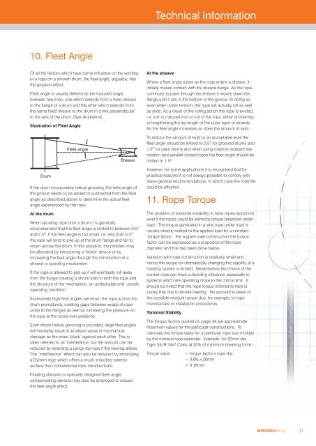
Technical Information10. Fleet AngleOf all the factors which have some influence on the windingof a rope on a smooth drum, the fleet angle, arguably, hasthe greatest effect.Fleet angle is usually defined as the included anglebetween two lines, one which extends from a fixed sheaveto the flange of a drum and the other which extends fromthe same fixed sheave to the drum in a line perpendicularto the axis of the drum. (See illustration).Illustration of Fleet AngleAt the sheaveWhere a fleet angle exists as the rope enters a sheave, itinitially makes contact with the sheave flange. As the ropecontinues to pass through the sheave it moves down theflange until it sits in the bottom of the groove. In doing so,even when under tension, the rope will actually roll as wellas slide. As a result of the rolling action the rope is twisted,i.e. turn is induced into or out of the rope, either shorteningor lengthening the lay length of the outer layer of strands.As the fleet angle increases so does the amount of twist.Fleet angleSheaveTo reduce the amount of twist to an acceptable level thefleet angle should be limited to 2.5 O for grooved drums and1.5 O for plain drums and when using rotation-resistant lowrotation and parallel-closed ropes the fleet angle should belimited to 1.5 O .DrumIf the drum incorporates helical grooving, the helix angle ofthe groove needs to be added or subtracted from the fleetangle as described above to determine the actual fleetangle experienced by the rope.At the drumWhen spooling rope onto a drum it is generallyrecommended that the fleet angle is limited to between 0.5 Oand 2.5 O . If the fleet angle is too small, i.e. less than 0.5 O ,the rope will tend to pile up at the drum flange and fail toreturn across the drum. In this situation, the problem maybe alleviated by introducing a ‘kicker’ device or byincreasing the fleet angle through the introduction of asheave or spooling mechanism.If the rope is allowed to pile up it will eventually roll awayfrom the flange creating a shock load in both the rope andthe structure of the mechanism, an undesirable and unsafeoperating condition.Excessively high fleet angles will return the rope across thedrum prematurely, creating gaps between wraps of ropeclose to the flanges as well as increasing the pressure onthe rope at the cross-over positions.Even where helical grooving is provided, large fleet angleswill inevitably result in localised areas of mechanicaldamage as the wires ‘pluck’ against each other. This isoften referred to as ‘interference’ but the amount can bereduced by selecting a Langs lay rope if the reeving allows.The “interference” effect can also be reduced by employinga Dyform rope which offers a much smoother exteriorsurface than conventional rope constructions.However, for some applications it is recognised that forpractical reasons it is not always possible to comply withthese general recommendations, in which case the rope lifecould be affected.11. Rope TorqueThe problem of torsional instability in hoist ropes would notexist if the ropes could be perfectly torque balanced underload. The torque generated in a wire rope under load isusually directly related to the applied load by a constant‘torque factor’. For a given rope construction the torquefactor can be expressed as a proportion of the ropediameter and this has been done below..Variation with rope construction is relatively small andhence the scope for dramatically changing the stability of ahoisting system is limited. Nevertheless the choice of thecorrect rope can have a deciding influence, especially insystems which are operating close to the critical limit. Itshould be noted that the rope torque referred to here ispurely that due to tensile loading. No account is taken ofthe possible residual torque due, for example, to ropemanufacture or installation procedures.Torsional StabilityThe torque factors quoted on page 34 are approximatemaximum values for the particular constructions. Tocalculate the torque value for a particular rope size multiplyby the nominal rope diameter. Example: for 20mm dia.Tiger 34LR 34x7 Class at 20% of minimum breaking force:-Torque value= torque factor x rope dia.= 0.8% x 20mm= 0.16mmFloating sheaves or specially designed fleet anglecompensating devices may also be employed to reducethe fleet angle effect.BRIDON <strong>Mining</strong>31