VIBRATORY FEEDERS
VIBRATORY FEEDERS
VIBRATORY FEEDERS

Create successful ePaper yourself
Turn your PDF publications into a flip-book with our unique Google optimized e-Paper software.
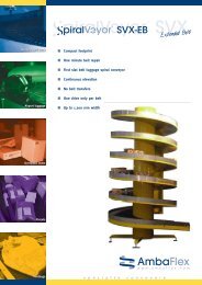
®HEAVY DUTY<strong>VIBRATORY</strong> <strong>FEEDERS</strong>HI-VI ELECTROMAGNETICHeavy-duty units for largecapacity and difficult materialhandling operations – now withgreater feeding capability.• Electro-permanent magnet drive• AC Operation• Simple control• Encapsulated coils• Variety of trays• Enclosed drive element• Low power consumption• 3 year warrantyFEATURES• Up to 20% greater feedingcapacity than previous modelsO N LY F R O M E R I E ZEriez’ unique Hi–Vi magnetic drive circuit providesa simple yet powerful solution to difficultmaterial feeding applications.Feed more for less. Up to 20% greater capacityof Eriez Heavy Duty Vibratory Feeders meansgreater productivity at lower cost. In addition,you get all the features that for years havemade Eriez Feeders the leaders in quality anddependability.Electro–Permanent Magnetic DriveThe basic simplicity of a drive powered by alternatelyopposing and attracting magnetic forcesassures low maintenance. There are no slidingor rotating parts. Power consumption is low,installation easy. The positive driving force ofEriez units provides stability, control, and unexcelledaccuracy.AC OperationNo rectifiers are required; feeders are simplywired into AC lines.Simple ControlsCompact variable transformer–type controls regulatefeeder speed by varying applied voltage.Control is stepless from 0 to 100 % of capacity,with excellent linearity. Almost no heat is generated.SCR controls are available for automatedVB-3301Z
®MODEL 65BFOR FEEDING UP TO180 TONS (162 MT)PER HOURThe 65B provides a wide capacity range tofeed controlled amounts from a few poundsto 180 tons (162 mt) per hour, for materialsweighing 100 lb/ft3 (1.6 g/cu cm), andeven more if operated with more downslopeand skirtboards. All units are available witheither under–drive or overhead–drives (pleasespecify). Capacity is based on 24 x 30 inch(610 x 762 mm) tray properly installed withskirtboards.Power SupplyFull Load Power InputShipping Weight115V, 230V, 460V, or 575V50–60 Cycles, Single Phase8 Amp at 230V750 lb. (340 kg)SPECIFICATIONS65B OVERHEAD–DRIVE STANDARD TRAYSSIZE A B C D E F G H J K10 x 60in 10 60 17-1/4 15-1/2 32-3/8 65-1/4 62-1/2 34-5/8 15-1/2 20-5/8mm 254 1524 438 393 822 1656 1587 879 394 525KF(4) 1 I.D. EYEBOLTSSUSP. MOUNTINGJ11 1 /229212 x 54in 12 54 19-1/4 12-3/4 29-5/8 60-1/8 56-1/4 29-1/2 13 14-3/8mm 305 1372 489 325 752 1527 1429 749 330 3654102DE16 x 4818 x 42in 16 48 23-1/4 10-3/8 27-1/4 52-3/8 50-3/8 25-3/8 11 12mm 406 1219 591 264 692 1332 1279 644 279 305in 18 42 25-1/4 10-5/8 25-1/2 51-1/4 43-1/2 31-1/8 11 12-3/8mm 457 1067 641 270 648 1300 1105 791 278 314BG23 7 /860619 1 /44891 1 /23810H615224 x 30in 24 30 31-1/4 9-3/4 25-7/8 32-1/2 31-7/8 22-7/8 11-7/8 10-7/8mm 610 762 794 247 657 827 810 580 302 276INCHESMILLIMETERSAC65B UNDER–DRIVE STANDARD TRAYSSIZE A B C D E F G H J10 x 60in 10 60 23-3/4 6-3/4 22-7/8 9-1/2 41-7/8 4-1/8 43-5/8mm 254 1524 603 171 581 242 1065 104 110712 x 54in 12 54 23-7/8 7-1/2 22-1/4 13-5/8 41-7/8 4-1/2 43-1/4mm 305 1372 606 189 564 346 1064 115 109716 x 48in 16 48 23-1/4 7-7/8 21-1/2 13-1/2 35-3/8 4-5/8 36-1/2mm 406 1219 591 199 547 344 898 118 92718 x 42in 18 42 25-1/4 8-7/8 21-1/2 15-3/4 32-3/8 6-3/8 33-5/8mm 457 1067 641 226 546 400 823 162 85324 x 30in 24 30 31-1/4 9-3/8 19-7/8 19-3/16 28-5/8 6 29mm 610 762 794 237 505 487 728 152 73710Ø x 6012Ø x 48CONSULT HOME OFFICE14Ø x 36E12516 1 /241911279F12 1 /2318INCHESMILLIMETERSGJCA12 1 /231819 1 /448923 3 /46034102(4) 1 I.D. EYEBOLTSSUSP. MOUNTINGBH6152101 1 /238D5
®MODEL 75BFOR FEEDING UP TO350 TONS (315 MT)PER HOURThe popular 75B has a feeding capacity of 350tons (315 mt) per hour. With its precise controlof this feed rate it is ideal for use in proportioningaggregates and other materials. Fine orcoarse, large or small bulk materials are fedequally well. Capacity is based on 30 x 48inch (762 x 1219 mm) tray properly installedwith skirtboards.Power SupplyFull Load Power InputShipping Weight115V, 230V, 460V, or 575V50–60 Cycles, Single Phase15 Amp at 230V1575 lb. (714 kg)SPECIFICATIONS75B OVERHEAD–DRIVE STANDARD TRAYSSIZE A B C D E F G H J K14 x 78in 14 78 22-1/2 20-1/8 37-3/4 85-3/8 80-1/4 39 16-1/4 19-7/8mm 355 1981 570 512 959 2169 2038 990 412 50618 x 72in 18 72 27 15-3/8 34 73-7/8 74-1/4 30-1/2 12-7/8 15-5/8mm 457 1829 636 391 864 1877 1887 776 327 39624 x 60in 24 60 31-3/4 14-1/8 32-3/8 66 62-3/8 35-1/2 14 17-7/8mm 610 1524 806 357 822 1678 1584 901 355 45530 x 48in 30 48 39 10 30 57-7/8 50-7/8 36-3/8 13-1/8 15-3/8mm 762 1219 991 254 762 1470 1292 924 334 39136 x 42in 36 42 45 10 30 57-1/8 45 36-3/8 13-1/8 9-1/2mm 914 1067 1143 254 762 1470 1143 924 334 2415127KINCHESMILLIMETERSBF(4) 1 1 /2 I.D. EYEBOLTSSUSP. MOUNTINGJG27 1 /469222 3 /4578107178H14356DEAC75B UNDER–DRIVE STANDARD TRAYSSIZE A B C D E F G H J14 x 78in 14 78 22-1/2 12-3/4 32-3/4 9-5/8 54-1/4 11-3/8 55-5/8mm 356 1981 572 323 833 245 1377 288 141418 x 72in 18 72 27 8-15/16 27-23/32 12-15/32 55-1/4 6-9/16 57-13/32mm 457 1829 686 227 704 317 1403 167 145824 x 60in 24 60 33 10-3/8 27-1/4 18-1/2 41-1/4 8-1/8 43-1/8mm 610 1524 838 265 693 471 1049 206 109430 x 48in 30 48 38-1/2 13 27-3/4 24 39-1/2 9-7/8 41-1/4mm 762 1219 978 329 705 611 1005 250 1049E1 3 /4442255916406F14 1 /4362G5127JCAB(4) 1 1 /2 I.D. EYEBOLTSSUSP. MOUNTINGH107178D36 x 42in 36 42 44-1/2 6-3/4 20-5/8 26-1/8 37-5/8 9 39-7/8mm 914 1067 1130 173 525 663 957 229 1012INCHESMILLIMETERS10Ø x 9612Ø x 8414Ø x 7216Ø x 60CONSULT HOME OFFICE1743222 3 /457927 1 /46927
®MODEL 85BFOR FEEDING UP TO420 TONS (378 MT)PER HOURThe 85B, with a feed rate of 420 tons (378 mt)per hour, provides high capacity in a compactsize. With its wide flat tray it can easily handlebig bulky chunks such as rocks, coal and othermined materials. Capacity is based on 36 x48 inch (914 x 1219 mm) tray properly installedwith skirtboards.Power SupplyFull Load Power InputShipping Weight230V, 460V, or 575V50–60 Cycles, Single Phase25 Amp at 230V2400 lb. (1090 kg)SPECIFICATIONS85B OVERHEAD–DRIVE STANDARD TRAYSSIZE A B C D E F G H J K18 x 84in 18 84 27-5/8 19-3/4 40-1/8 87-1/8 86-1/8 38-1/8 17-1/2 23-1/4mm 457 2134 702 500 1019 2213 2189 968 444 589KF(4) 1 1 /2 I.D. EYEBOLTSSUSP. MOUNTINGJ14 1 /236824 x 7230 x 60in 24 72 32-1/2 15-3/4 34 81-7/16 74-5/16 35-3/4 12-15/16 15-1/4mm 610 1829 826 400 864 2069 1888 908 328 387in 30 60 39-1/2 14-7/8 34-3/4 71-7/8 62-5/8 37-3/4 15-1/8 14-3/8mm 762 1524 1003 377 883 1827 1590 958 384 3655127BG31 1 /28001 1 /238107179HDE36 x 48in 36 48 45 12-3/4 32-3/4 60 50-3/4 40-1/4 15-7/8 17mm 914 1219 1142 324 832 1524 1289 1023 403 431INCHESMILLIMETERS27686AC85B UNDER–DRIVE STANDARD TRAYSSIZE A B C D E F G H J18 x 84in 18 84 27-5/8 10-1/8 31 17-3/8 62-7/8 7 65-3/4mm 457 2134 702 257 786 442 1596 177 165924 x 72in 24 72 33-1/2 12-1/2 31-3/8 16-7/8 50-3/4 8 53mm 610 1829 851 317 797 429 1288 203 1346E22 1 /257218457F5127GB(4) 1 1 /2 I.D. EYEBOLTSSUSP. MOUNTINGH1 1 /238107178D30 x 60in 30 60 39-5/8 10-5/8 27-3/8 20-3/4 39-7/8 8-1/2 42-7/8mm 763 1524 1008 271 695 528 1013 217 108812516406JC36 x 4810Ø x 120in 36 48 45-5/8 11 25-7/8 24-1/4 39-3/8 7 42-1/4mm 914 1219 1159 280 657 616 999 179 1072INCHESMILLIMETERSA12Ø x 10814Ø x 96CONSULT HOME OFFICE184572768616Ø x 8431 1 /28008
®MODEL 98BFOR FEEDING UP TO550 TONS (495 MT)PER HOURYou can move up to 550 tons (495 mt) perhour with the 98B. Standard tray sizes goup to 7 feet (2134 mm) long. Multiple drivesare available on all heavy duty models wheremore than standard length is required. Thedrive unit is completely enclosed. Capacity isbased on 42 x 54 inch (1067 x 1372 mm) trayproperly installed with skirtboards.Power SupplyFull Load Power InputShipping Weight230V, 460V, or 575V50–60 Cycles, Single Phase35 Amp at 230V2600 lb. (1180 kg)SPECIFICATIONS98B OVERHEAD–DRIVE STANDARD TRAYSSIZE A B C D E F G H J K18 x 96in 18 96 27-5/8 20-3/4 43-5/8 96-5/8 98 37-3/8 17-3/4 23-1/2mm 456 2438 702 528 1108 2453 2490 948 451 59524 x 84in 24 84 33-5/8 19-3/4 44-1/8 90-5/8 86 45 19-5/8 24-5/8mm 610 2134 854 501 1121 2303 2186 1143 500 62630 x 72in 30 72 39-5/8 16-3/8 38-1/4 81-3/4 74-1/4 38-1/2 15-1/2 15-1/4mm 762 1829 1006 417 972 2075 1886 977 395 38736 x 60in 36 60 45-5/8 16-1/4 38-1/8 69-7/8 62-3/8 42 18-1/4 18-3/4mm 914 1524 1159 411 968 1776 1586 1066 463 47642 x 54in 41-7/8 54 51-5/8 13-3/8 36 65-1/2 56-5/8 41 15-1/2 16-7/8mm 1063 1372 1311 339 914 1663 1438 1043 393 4285127KINCHESMILLIMETERSJBF(4) 1 1 /2 I.D. EYEBOLTSSUSP. MOUNTINGG31 1 /280027686251107179H16406DEAC98B UNDER–DRIVE STANDARD TRAYSSIZE A B C D E F G H J18 x 96in 18 96 27-5/8 11-3/8 34-5/8 18-3/8 62-5/8 12-1/8 61-1/4mm 457 2438 702 289 878 468 1592 309 155624 x 84in 24 84 33-5/8 11-5/8 32-5/8 14 62-1/4 8-3/4 63-3/8mm 610 2134 854 296 829 356 1582 221 1610FE25635164065127GB(4) 1 1 /2 I.D. EYEBOLTSSUSP. MOUNTINGH251107179D30 x 7236 x 6042 x 54in 30 72 39-5/8 12 30-7/8 20-1/4 56-5/8 8-1/2 57-3/4mm 762 1829 1006 305 785 514 1440 217 1467in 36 60 45-5/8 18-1/8 35 22-1/2 43-1/2 14-5/8 44-1/2mm 914 1524 1159 460 889 571 1106 373 1130in 42 54 51-5/8 14-1/2 30 31 57 8-3/4 57-5/8mm 1067 1372 1311 368 762 787 1448 222 14641 1 /23816406INCHESMILLIMETERSJCA225592768631 1 /28009
®MODEL 105BFOR FEEDING UP TO700 TONS (630 MT)PER HOURThe 105B has a rated capacity up to 700 tons(630 mt) per hour. Rugged construction andthe Eriez patented magnetic drive make thisan ideal unit for handling abrasives, slag, coal,ores, grains, or wherever controlled feeding oflarge tonnages is required. Capacity is basedon 42 x 60 inch (1067 x 1524 mm) tray properlyinstalled with skirtboards.Power SupplyFull Load Power InputShipping Weight230V, 460V, or 575V50–60 Cycles, Single Phase35 Amp at 230V2800 lb. (1270 kg)SPECIFICATIONS105B OVERHEAD–DRIVE STANDARD TRAYSSIZE A B C D E F G H J K24 x 96in 24 96 33-1/2 20-3/8 43 101-1/2 98 36 17-7/8 17-3/16mm 610 2438 851 518 1092 2579 2489 914 453 43730 x 84in 30 84 39-1/2 18-1/8 40-5/8 89-1/2 86-1/8 35-7/8 16-7/8 17-1/4mm 761 2134 1003 459 1032 2274 2189 911 428 43836 x 72in 36 72 45-1/2 14-7/8 37-1/2 76-3/4 74-3/8 35-1/8 15-3/4 17-1/2mm 914 1829 1156 376 953 1951 1889 894 399 44542 x 60in 42 60 51-1/2 14-7/8 36-3/4 73 62-9/16 41-1/8 17 15-1/2mm 1067 1524 1308 379 933 1853 1589 1045 433 39448 x 54in 48 54 57-1/4 14-1/2 35-7/8 73 56-5/8 43-5/8 16-5/8 12mm 1219 1372 1453 369 911 1853 1439 1107 421 3055127KINCHESMILLIMETERSJBF(4) 1 1 /2 I.D. EYEBOLTSSUSP. MOUNTINGG31 1 /280027686251107179H16406DEAC105B UNDER–DRIVE STANDARD TRAYSSIZE A B C D E F G H J24 x 96in 24 96 33-1/2 10 32-7/8 9 69-1/4 6-7/8 70-1/4mm 610 2438 851 253 834 229 1758 176 178430 x 84in 30 84 39-1/2 10-7/8 31-3/4 13-1/8 60-5/8 8-1/4 61-3/8mm 762 2133 1003 276 806 335 1540 209 1559FE25635164065127GB(4) 1 1 /2 I.D. EYEBOLTSSUSP. MOUNTINGH251107179D36 x 7242 x 6048 x 54in 36 72 45-1/2 14-3/4 31-1/8 23-1/2 61-1/8 9-3/8 62-1/4mm 914 1829 1158 373 792 597 1553 238 1581in 42 60 51 13-3/8 24-1/4 25-7/8 57-1/8 10-1/2 58-7/8mm 1067 1524 1295 340 615 658 1450 268 1495in 48 54 57 13-1/8 28-3/4 27 48-1/4 12-1/8 50mm 1219 1372 1448 334 731 686 1227 309 12701 1 /23816406INCHESMILLIMETERSJCA225592768631 1 /280010
®MODEL 115BFOR FEEDING UP TO850 TONS (765 MT)PER HOURThe 115B facilitates the smooth and dependabletransfer of abrasives, slag, coal, ores andgrain at up to 850 tons (765 mt) per hour. Theunit represents an excellent choice whenevercontrolled feeding must be accomplished in acost–effective manner. Specially designed towithstand many years of hard work, the unit’srugged construction includes a 48 x 72 inch(1215 x 1828 mm) tray and below–deck oroverhead–drive (please specify).Power SupplyFull Load Power InputShipping Weight230V, 460V, or 575V50–60 Cycles, Single Phase44.8 Amp at 460V5075 lb. (2302 kg)SPECIFICATIONS115B OVERHEAD–DRIVE STANDARD TRAYSSIZE A B C D E F G H J KKF2255930 x 108in 30 108 45-1/2 22-7/8 47-1/4 114-5/8 110 44-3/4 24 19mm 762 2741 1156 582 1200 2912 2793 1137 610 483J(4) 2 3 /16 I.D.EYEBOLTSSUSP. MOUNTING36 x 9642 x 8448 x 72in 36 96 51-1/4 22-1/2 46-1/2 110-3/8 98-3/8 51-3/4 23-5/8 18-5/8mm 914 2439 1302 573 1181 2804 2499 1314 599 473in 42 84 57-1/4 20-3/8 44-1/4 101 85-1/8 52-5/8 24-5/8 15-5/8mm 1067 2134 1454 517 1124 2567 2163 1336 626 397in 48 72 63-1/4 20-1/4 43-1/2 87-1/2 74-1/2 53-1/2 26-5/8 19-1/2mm 1219 1829 1607 515 1105 2223 1893 1360 678 4945127INCHESMILLIMETERSBG25138 1 /497236915107179HDE54 x 60in 54 60 69-1/4 12-1/8 37 72-7/8 62-5/8 44-5/8 22 13-1/8mm 1372 1524 1757 307 940 1850 1590 1134 559 335AC115B UNDER–DRIVE STANDARD TRAYSSIZE A B C D E F G H J30 x 108in 30 108 45-1/4 12-5/8 37-3/4 24-7/8 74-3/8 14-3/4 113-1/4mm 762 2743 1149 320 960 632 1889 375 287736 x 96in 36 96 51-1/4 14 37-1/8 31-3/8 81-1/2 12 108mm 914 2438 1302 356 944 798 2070 304 2743E15 1 /239434 3 /4883F5127GHB(4) 2 3 /16 I.D.EYEBOLTSSUSP.MOUNTING251107179D42 x 8448 x 7254 x 60in 42 84 57-1/4 14-3/8 35-1/4 32-1/8 54-1/8 14-1/8 96-7/8mm 1067 2134 1454 367 897 817 1375 358 2462in 48 72 63-3/8 18-1/2 33-1/4 35-1/2 43-3/8 14-3/8 88-3/8mm 1219 1829 1609 471 846 902 1101 365 2245in 54 60 69-1/4 11-3/8 28-1/8 37-1/4 47-1/2 8 78-1/4mm 1372 1524 1759 288 713 945 1206 203 1989410219 1 /4489INCHESMILLIMETERSCAJ246103691538 1 /497211
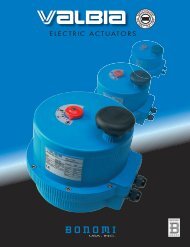
®UniformFlowdHOPPERDESIGN FOROPTIMUMPERFORMANCEDETERMINING <strong>VIBRATORY</strong>FEEDER CAPACITYThe capacity of a vibratoryfeeder is given by:Q = W x d x D x vKWhere: English MetricQ = Capacity TPH MTPHW = Tray width inches mmd = Material depth inches mmD = Density lb/cu ft g/cu cmv = Flow velocity ft/min m/minK = Constant 4,800 16,700DETERMINING GATEHEIGHTDeadZoneUniformFlowdDeadZoneHOPPER DESIGNIf you plan to build a new hopper or modify anexisting one for installation with an Eriez vibratoryfeeder or screen, its design should adhereto certain guidelines in order to obtain the ratedcapacity of the feeder, achieve the required dischargeor delivery rate, prevent bridging, archingor ratholing.Along with the hopper design, flow velocity (v) isdependent on material characteristics such asparticle size, size distribution and moisture content.Rated capacities require ideal conditions.IMPORTANCE OF THETRANSITION SECTIONA hopper’s transition section - the part of thestructure between the main bin and the feeder- plays a very significant role in obtaining therated capacity of a feeder. An improperlydesigned hopper or transition section can reducefeeder capacities by as much as 30%.The bottom of the hopper, for example, shouldbe almost as wide as the feeder tray to providefull–width feeding. Clearance of 1" (25 mm)between hopper and tray is recommended.Throat OpeningFor random sized material, the hopper throatopening (T) should be 2-1/2 - 3 times the largestparticle size. For near–sized material, thehopper throat opening (T) should be 3 timesthe particle size. The throat opening shouldnot exceed 30% of the tray length, however, or“headloading” may overpower the ability of thefeeder to move the material. In some cases,load deflectors (i.e., angle iron) will be requiredto obtain satisfactory operation.NonuniformFlowdGate HeightThe gate height (H) should increase proportionallyto the particle size and to the depth of flow(measured at the end of the trough) required toNonuniformdesired discharge rate. Generallydeliver theFlowspeaking, the dgate height should be at leasttwice the size of the largest particle size, adjustableby means of a slide gate. During operation,the gate height should be 1.2 - 1.5 timesthe depth of material (d) needed to meet capacityrequirements.Uniform flow patterns also require that the gateheight (H) be 1 - 2 times (2 is preferable) thethroat dimension (T). When h becomes lessthan T, material flow patterns are not uniformand usually result in dead zones where little orno flow occurs.ACHIEVING UNIFORM FLOWThere is a natural tendency of feeders to drawmaterial from the front portion of the hopper.However, a properly designed hopper will causematerial to also flow onto the rear of the feedertrough, creating a uniform flow pattern (Figure 2).The rear wall of the hopper’s transition sectionshould be quite steep - at a slope of 60° ormore - to assure flow of material along the rearwall surface. In contrast, the slope of the frontwall may be more shallow; an angle 5 - 10° lessthan the rear wall is acceptable.INSTALLATION OFSKIRTBOARDSTo obtain the rated capacity of larger Eriezfeeders, a burden depth higher than the traysides must be carried by the feeder. To containthe material and prevent spillover, skirtboardsshould be installed on both sides of the gateopening, extending to the end of the trough.To prevent any hang–ups or restrictions of materialflow, the skirt boards should flare slightly,becoming wider at the discharge end, and alsoshould taper away from the bottom of the feederalong the length of the trough. The flare andtaper rate should be at least 1/2" per foot (40mm per m) of feeder length.Skirt boards are nearly always required in installationswhere the feeder pan is given downslopein order to use gravity to boost delivery rate.Some installations have increased capacity bymore than 50% with a 10° downslope. As a ruleof thumb, each degree of downslope increasesdelivery by 2%.A minimum of 1" (25 mm) clearance must be maintainedbetween the skirtboards and the feeder tray.Movement of the tray must not be restricted byrigid attachment to nearby structures.Approx.60° Static Angle of Reposeof MaterialBin Vibrator6" to 12" (152 to 305 mm)High Vertical Section at BackFeeder DriveTHApprox.45°Adjustable Sliding GateSkirt Board Attached to Hopper andFlared Up and Outward at a Rate ofApprox. 1/2" Per Ft (40 mm Per m)0 to 12° DownslopeT = Hopper Throat OpeningH = Gate Height Openingd = Material Depth of FlowFigure 3. Typical Hopper and Skirtboard Installationd12
<strong>VIBRATORY</strong>FEEDERCONTROLSA variety of control arrangements, some ofthem illustrated below, are available for usewith Eriez Heavy Duty Feeders. All of these simple, rugged controls have thebasic function of varying the appliedline voltagefrom zero to 100%, thus varying the feedrate from zero to maximum. Stepless controlassures the exact feed rate needed for any application and eliminates surges when movingfrom one increment to another.No rectifier is needed with Eriez Hi–Vi controls;they can be wired into any AC line. STANDARD MANUAL CONTROLA variable transformer or potentiometer controls feeder output with excellentlinearity from 0 to 100% of capacity. MULTIPLEMANUAL CONTROLIndividual variable transformers or potentiometers for a number of feeders. A mastermay be added to increase or decrease total output. Individual controls need not bereadjusted to maintain a preset percentage of the total product. DUAL-RATE CONTROL Two variable transformers or potentiometer in a single housing, one set at a fastfeed rate and the other at a dribble feed for accuracy. VERNIER CONTROLTwo variable transformers or potentiometers wired in tandem to “fine tune” the output of a single feeder for extremely precise control. Controls are enclosed in compact steel housings.For dusty or hazardous locations special gasketed and totally enclosed electrical housings designed to provide protection against oil,water, dust, etc. can be provided.. Figure4. Eriez Feeders are available with signal followingcontrols that accept a signal from your processing equipment or PLC to automatically increase or decrease feed rate. PNEUMATIC CONTROLA 3 to 15 psi (0.2 to 1.0 Bar) pneumatic signal is used to vary voltage and thuscontrol feed rate. LOAD MONITORING CONTROLMotor load is monitored to reduce or increase feed when motor demand becomesexcessive, to keep crushers, grinders, impactors operating at maximum without overloading. SCR CONTROL Feeder output is varied automatically by the use of a small current signal to increaseor decrease feed rate. For use in systems where process variables can be convertedinto a varying current signal. CONSTANT FEED RATE CONTROL A sensor on the feeder tray is used to send a signal to the control, maintaining aconstant rate of feed. 13®
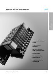
®GRIZZLIES ANDSPECIAL TRAYSVibratory feeders with grizzly trays are usedfor a variety of scalping or coarse screeningoperations. Screened trays provide evengreater control in separation by size, dedustingor dewatering. On all types of trays, theadvantages of gentle material handling andaccurate control of feed rates are retained.Eriez’ long experience in designing specialtrays for special applications, plus computerizationof vibratory feeder variables, means thatunusual requirements can be met quickly andeconomically.A three–deck screening feeder dischargesoversize and undersize products to one sidewhile the desired material flows off the end.Totally enclosed trays are used to protect theproduct, or in some cases, the environment, bycontaining dust within the system.The tray on this overhead–drive unit channels thefeed to the center of the conveyor belt.14
®Vibratory sand classifier is used in conjunction with woodfired boiler, to reclaim unburned wood for recirculationthrough boiler. Screens are used to sift out ash and sand.Screening feeders takemany forms, from removingfines to separating plasticparts as shown here.Vibratory drives can be produced in the overheadposition, and tray liners can be electrically heated toprevent product from sticking to tray. (Note junctionbox at rear of tray).Cascading screening decks on a portable unittumble the material for better separation.The tray on this feeder is slotted at an angle tospread material evenly over a conveyor belt whichwill be installed at right angles to the tray.A water jacket cools thistubular tray used to feed culletinto a furnace.15
<strong>VIBRATORY</strong>CONVEYORSMultiple drive units, mounted either under orover a single tray, extend the advantages ofvibratory feeding to conveying. Variable transformercontrols give precise control of feedrates, installation is simple and maintenance islow. Either open or closed trays are availablein a variety of widths, with intake or dischargeopenings as required. Lengths up to 65 feet(20 m) can be provided.Eriez and Eriez Magnetics are registered trademarks of Eriez Manufacturing Co., Erie, PA©2005 Eriez Magnetics • All Rights ReservedWeb Site: http://www.eriez.come-mail: eriez@eriez.comTelephone 814/835-6000 • 800/345-4946 • Fax 814/838-4960 • International Fax 814/833-3348HEADQUARTERS: 2200 Asbury Road, P.O. Box 10608, Erie, PA 16514-0608 U.S.A.MANUFACTURING : Australia • Brazil • Canada • China • India • Japan • Mexico • South Africa • United Kingdom • United StatesWorld Authority in Advanced Technology for Magnetic, Vibratory and Metal Detection Applications605-1M-SG-AP Eriez Manufacturing Co. Printed in USA®