Setrox S Active Fixation Leads - BIOTRONIK USA - News
Setrox S Active Fixation Leads - BIOTRONIK USA - News
Setrox S Active Fixation Leads - BIOTRONIK USA - News

Create successful ePaper yourself
Turn your PDF publications into a flip-book with our unique Google optimized e-Paper software.
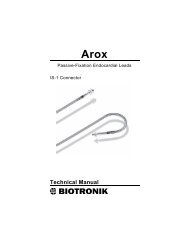
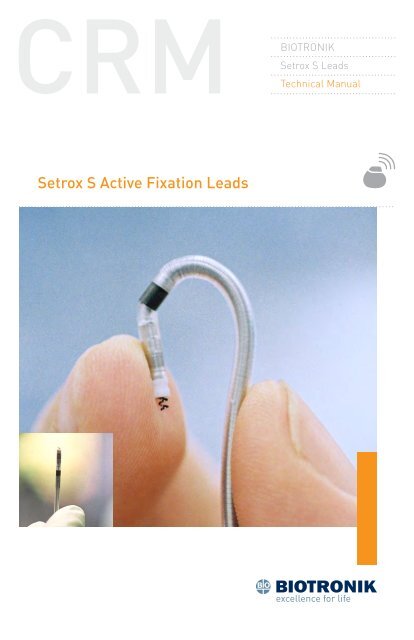
<strong>BIOTRONIK</strong><strong>Setrox</strong> S <strong>Leads</strong>Technical Manual<strong>Setrox</strong> S <strong>Active</strong> <strong>Fixation</strong> <strong>Leads</strong>
CautionFederal (U.S.A.) law restricts this device to sale by, or on theorder of, a physician.©2011 <strong>BIOTRONIK</strong>, Inc., all rights reserved.
Contents<strong>Setrox</strong> S Steroid-Eluting <strong>Leads</strong> Technical Manual i1. Device Description............................................................................. 12. Indications for Use............................................................................. 33. Contraindications............................................................................... 54. Warnings and Precautions................................................................. 75. Potential Adverse Events................................................................. 116. Clinical Studies................................................................................ 137. General Information on Product Handling....................................... 157.1 Sterilization and Storage................................................................157.2 Opening the Sterile Container........................................................157.3 Package Content and Accessories..................................................168. Implantation.................................................................................... 198.1 General Guidelines..........................................................................198.2 Measurement of the Capture Threshold and Intracardiac Signals....248.3 Lead Connection to the Pulse Generator.......................................259. Disclaimer........................................................................................ 2910. Technical Specifications................................................................. 31
ii <strong>Setrox</strong> S Steroid-Eluting <strong>Leads</strong> Technical Manual
1. Device Description<strong>Setrox</strong> S Steroid-Eluting <strong>Leads</strong> Technical Manual 1The <strong>BIOTRONIK</strong> <strong>Setrox</strong> S transvenous, steroid-eluting, active fixationendocardial lead family is designed for permanent pacing andsensing. <strong>Active</strong> fixation pacing leads with a bipolar (BP) IS‐1 connectorconfiguration are designed for use in conjunction with implantable pulsegenerators with IS-1 compatible headers. The leads may be used withsingle- or dual-chamber pulse generators.<strong>Setrox</strong> S leads feature an electrically active extendable/retractablefixation helix for use in lead placement. The helix is extended andretracted by rotating the connector pin with a fixation tool. Both thefixation helix and ring electrode are comprised of a platinum/iridiumalloy base with a fractal iridium surface. The fractal surface of the leadelectrodes creates a larger effective surface area, as a result maximizesthe myocardial interface, which is a major factor in determining a lead’ssensing characteristics. All leads are multifilar and insulated withmedical grade silicone.The distal tip of the <strong>Setrox</strong> S lead consists of a steroid-eluting collar,containing 0.75 mg of dexamethasone acetate (DXA). Upon exposure tobody fluids, the steroid elutes from the collar into the body tissue bydiffusion. Release of the steroid is intended to decrease the inflammatoryresponse at the contact site between the lead tip and the endocardium,thereby decreasing the elevated pacing thresholds of the endocardiallead that often occur after lead implantation.<strong>Setrox</strong> S leads have straight distal ends (<strong>Setrox</strong> S xx) and are intendedfor placement in either the right atrium or right ventricle. The “xx”represents the lead length in centimeters. The <strong>Setrox</strong> S leads areavailable in the following configurations: <strong>Setrox</strong> S 45, <strong>Setrox</strong> S 53, and<strong>Setrox</strong> S 60.CautionBecause of the numerous available 3.2 mm configurations, e.g.,the IS‐1 and VS‐1 standards, lead/pulse generator compatibilityshould be confirmed with the pulse generator and/or leadmanufacturer prior to the implantation of a pacing system.NOTE:IS‐1, wherever stated in this manual, refers to theinternational standard, whereby leads and generators fromdifferent manufacturers are assured a basic fit. [ReferenceISO 5841-3:1992(E)].See Section 10 for the technical specifications of the <strong>Setrox</strong> S leads.
2. Indications for Use<strong>Setrox</strong> S Steroid-Eluting <strong>Leads</strong> Technical Manual 3<strong>BIOTRONIK</strong>’s <strong>Setrox</strong> S xx transvenous, steroid‐eluting, active fixationendocardial leads are indicated for permanent pacing and sensing. <strong>Active</strong>fixation pacing leads with a bipolar (BP) IS‐1 connector configurationare designed for use in conjunction with implantable pulse generatorswith IS-1 headers. The leads may be used with single or dual chamberpacing systems.The <strong>Setrox</strong> S xx lead models are intended for placement in either theright atrium or right ventricle.
4 <strong>Setrox</strong> S Steroid-Eluting <strong>Leads</strong> Technical Manual
<strong>Setrox</strong> S Steroid-Eluting <strong>Leads</strong> Technical Manual 53. ContraindicationsTransvenous endocardial pacing leads are contraindicated in thepresence of severe tricuspid valvular disease and in patients withmechanical heart valves. The <strong>Setrox</strong> S lead is additionally contraindicatedfor patients who cannot tolerate a single systemic dose of up to 1.3 mgof dexamethasone acetate (DXA).
6 <strong>Setrox</strong> S Steroid-Eluting <strong>Leads</strong> Technical Manual
4. Warnings and Precautions<strong>Setrox</strong> S Steroid-Eluting <strong>Leads</strong> Technical Manual 7The performance of a cardiac pacing system depends on properinteraction of its three components: the pulse generator, the lead(s),and the patient. Abnormalities or changes in the electrical propertiesof any of the three components, or their interfaces with each other, maydirectly affect function of the entire system. Correct lead implantation iscritical to safe and effective performance of the pacing system.The pacing system may cease to function at any time due to medical and/or technical complications:Medical ComplicationsMedical complications of the pacemaker treatment may include, butare not limited to: fibrotic tissue formation, thrombosis, embolism,elevated thresholds, body rejection phenomena, cardiac tamponade,muscle and nerve stimulation, myocardial perforation, erosion of thepulse generator/lead through the skin, infection and pacemakerinduceddysrhythmia (some of which could be life-threatening such asventricular fibrillation).Technical ComplicationsIncorrect operation of the pacing system may be caused by but is notlimited to: improper lead placement, lead dislodgement, lead fracture,loss of insulation integrity, battery depletion, or electrical componentfailure.Potentially Harmful Therapeutic and Diagnostic ProceduresAs an implanted pacing lead is a direct, low resistance path to themyocardium for electrical current, the observance of high standards ofelectrical safety is required. Electrosurgical instruments, for example,could generate voltages of such amplitude that a direct couplingbetween the tip of the electrocautery device and the implanted leadmay result, possibly inducing myocardial lesions or serious cardiacarrhythmias (e.g., fibrillation).Some therapeutic and diagnostic procedures (e.g., diathermy, MRI,electrocautery) may result in latent damage to the pacing system. Thisdamage may not be detected when testing the pulse generator functionimmediately after the procedure, but may become evident at a latertime, resulting in pacing system malfunction or failure.
8 <strong>Setrox</strong> S Steroid-Eluting <strong>Leads</strong> Technical ManualPrevention of Leakage Current ConductionPulse generators and testing equipment connected to the lead mustbe battery-powered. Proper grounding of line-powered devices in thevicinity of the patient is essential to prevent leakage currents arisingfrom such devices to be conducted via the lead’s terminal or any othernon-insulated part.Previously Implanted <strong>Leads</strong>It is generally recommended that a chronically implanted endocardiallead not be explanted. If it becomes necessary to abandon a lead, theconnector pin should be capped to prevent the transmission of electricalsignals to the heart.Storage TemperatureStorage at temperatures up to 25° C (77° F); excursions permitted from5° to 55° C (41° to 131° F). Exposure to temperatures outside this rangemay result in lead malfunction.Necessary Equipment for ImplantationDuring implantation the ECG should be recorded; a pacing systemanalyzer (PSA) and defibrillation equipment should always be readilyavailable.Handling the LeadThe lead should be handled very carefully at all times. Any severeapplication of force (bending, stretching, crimping, etc.) maypermanently damage the lead. The metal portion of the lead connectorshould not be touched.Stylet InsertionTo avoid damage to the lead, do not insert the stylet too rapidly nor useexcessive force when inserting the stylet into the lead.Lead/Pulse Generator CompatibilityBecause of the numerous available 3.2 mm configurations, e.g., theIS‐1 and VS‐1 standards, lead/pulse generator compatibility should beconfirmed with the pulse generator and/or lead manufacturer prior tothe implantation of a pacing system.
NOTE:<strong>Setrox</strong> S Steroid-Eluting <strong>Leads</strong> Technical Manual 9IS‐1, wherever stated in this manual, refers to the internationalstandard, whereby leads and generators from differentmanufacturers are assured a basic fit. [Reference ISO 5841-3:1992(E)].Extending/Retracting the <strong>Fixation</strong> HelixIn the event of previous handling or repositioning of the lead, more thanthe minimum number of rotations may be necessary to fully extend orretract the helix. Full helix extension should always be verified throughfluoroscopy.Anchoring SleeveAlways use an anchoring sleeve (lead fixation sleeve) when implanting alead. Use of the anchoring sleeve, which is provided with the lead, willlessen the possibility of lead dislodgement and protect the lead bodyfrom damage by a securing ligature.Measuring Intracardiac SignalsDepending on the PSA used, pacing may be interrupted during themeasurement of the intracardiac signals. <strong>BIOTRONIK</strong>’s ERA 300 PacingSystem Analyzer has back-up VVI pacing at a rate of 30 ppm during theintracardiac measurements.Chronic RepositioningIt is generally recommended that a chronically implanted endocardiallead not be explanted. Chronic repositioning or removal of activefixation leads may be difficult due to the presence of blood or fibrotictissue in the helix. If it becomes necessary to remove the lead withoutsuccessfully retracting the fixation helix, the lead should be rotatedcounter-clockwise during withdrawal in order to minimize the risk ofendothelial laceration. If it becomes necessary to abandon a lead, theconnector pin should be capped to prevent the transmission of electricalsignals to the heart.Setscrew AdjustmentThe pulse generator’s setscrew(s) must be retracted prior to insertingthe lead connector. Failure to back off the pulse generator’s setscrew(s)may result in damage to the lead(s), and/or difficulty connecting thelead(s).
10 <strong>Setrox</strong> S Steroid-Eluting <strong>Leads</strong> Technical ManualCross-Threading SetscrewTo prevent cross-threading the setscrew, do not back the setscrewcompletely out of the threaded hole. Leave the torque wrench in the slotof the setscrew while the lead is inserted.Tightening SetscrewDo not over-tighten the setscrew(s). Use only a torque wrench, whichautomatically prevents over-tightening.Sealing CapsFor pacemakers requiring sealing caps, secure a sealing cap over thesetscrew(s) to prevent pacemaker malfunction.
5. Potential Adverse Events<strong>Setrox</strong> S Steroid-Eluting <strong>Leads</strong> Technical Manual 11Potential complications resulting from the use of endocardial leadsinclude, but are not limited to: thrombosis, embolism, body rejectionphenomena, cardiac tamponade, pneumothorax, muscle/nervestimulation, valve damage, fibrillation, infection, skin erosion andventricular ectopy. Lead perforation through the myocardium has beenrarely observed. The table below summarizes some of the potentialsymptoms indicating a complication and possible corrective actions:Table 1: Potential Complications and Corrective ActionsSymptomLoss ofpacing orsensingIncrease/decrease inthresholdPotential ComplicationLead dislodgementLead fractureSetscrew penetrationof lead insulationImproper lead / pulsegenerator connectionFibrotic tissueformationPotential CorrectiveActionReposition leadReplace leadReplace leadReconnect lead topulse generatorAdjust pulsegenerator output;Replace/repositionlead
12 <strong>Setrox</strong> S Steroid-Eluting <strong>Leads</strong> Technical Manual
<strong>Setrox</strong> S Steroid-Eluting <strong>Leads</strong> Technical Manual 136. Clinical StudiesBecause the <strong>Setrox</strong> S lead is based on <strong>BIOTRONIK</strong>’s legally marketedSelox SR lead, engineering and animal tests were performed in lieu ofhuman clinical data.
14 <strong>Setrox</strong> S Steroid-Eluting <strong>Leads</strong> Technical Manual
<strong>Setrox</strong> S Steroid-Eluting <strong>Leads</strong> Technical Manual 157. General Information on Product HandlingThe following information generally applies to all transvenousimplantable leads, but does not attempt to describe all procedures to befollowed, precautions to be taken, or contraindications to be considered.7.1 Sterilization and StorageThe lead and its accessories have been sealed in a double blister plasticcontainer and gas sterilized with ethylene oxide. To assure sterility, thecontainer should be checked for integrity prior to opening. Should abreach of sterility be suspected, return the lead to <strong>BIOTRONIK</strong>.The blister package is shipped in an outer box, equipped with a qualitycontrol seal and product information label. The label contains the modelspecifications, technical data, serial number, shelf-life expiration date,sterilization and storage information of the lead.CautionStorage TemperatureStorage at temperatures up to 25° C (77° F); excursionspermitted from 5° to 55° C (41° to 131° F). Exposureto temperatures outside this range may result in leadmalfunction.Handling the LeadThe lead should be handled very carefully at all times. Anysevere application of force (bending, stretching, crimping,etc.) may permanently damage the lead. The metal portion ofthe lead connector should not be touched.Should a replacement lead be required, contact your local <strong>BIOTRONIK</strong>representative.7.2 Opening the Sterile ContainerThe lead is packaged in two plastic containers, one within the other.The two packages are individually sealed and then sterilized withethylene oxide gas. Due to the double packaging, the outside of theinner container is sterile and can be removed using standard aseptictechnique and placed in the sterile field.
16 <strong>Setrox</strong> S Steroid-Eluting <strong>Leads</strong> Technical ManualPeel off the sealing paper ofthe outer unsterile container asindicated by the arrow.Take out the inner sterile containerby the gripping tab and open itby peeling the sealing paper asindicated by the arrow.7.3 Package Content and AccessoriesThe <strong>Setrox</strong> S leads and the accessories provided in the inner blisterpackage with each lead are delivered sterile.Each <strong>Setrox</strong> S xx (available in 45, 53, and 60 cm lengths, xx) packagecontains the following:1 – <strong>Setrox</strong> S lead3 – S xx-K medium, straight ball-tipped stylets (one of which is preinserted)xx represents the stylet length of 45, 53, or 60 cm1 – S xx-F soft, straight ball-tipped styletsxx represents the stylet length of 45, 53, or 60 cm1 - S xx-J Stylets, J-shaped ball-tippedxx represents the stylet length of 45 or 53 cm1 - S xx-JL Stylets, J-shaped ball-tippedxx represents the stylet length of 45 or 53 cm1 – Unipolar Stylet Guide1 – Vein Lifter1 – Lead <strong>Fixation</strong> Sleeve (attached to lead)2 - <strong>Fixation</strong> Tools
<strong>Setrox</strong> S Steroid-Eluting <strong>Leads</strong> Technical Manual 17NOTE:The fixation tool and all stylets are also available as separatelypackaged accessories.
18 <strong>Setrox</strong> S Steroid-Eluting <strong>Leads</strong> Technical Manual
8. Implantation<strong>Setrox</strong> S Steroid-Eluting <strong>Leads</strong> Technical Manual 19The lead tip consists of a silicone rubber collar that contains a steroidagent. The steroid is used to reduce inflammation after the implantationand decrease the postoperative threshold increase caused byinflammation.8.1 General Guidelines<strong>Setrox</strong> S leads come with a regular straight ball-tipped stylet alreadyinserted.Verifying the Mechanical Function of the <strong>Fixation</strong> HelixPrior to implantation, test the operation of the fixation helix:1. Press both legs of the fixation tool together and place the mostdistal hole of the fixation tool on the connector pin.2. Practice extending the helix by rotating the tool clockwise until thehelix is completely exposed (a minimum of 8 complete clockwiserotations of the fixation tool). This number of rotations of thefixation tool should fully extend the helix to approximately 1.9 mm.(See following figure).
20 <strong>Setrox</strong> S Steroid-Eluting <strong>Leads</strong> Technical Manual3. Remove the fixation tool from the connector pin and release theproximal end of the lead body. Allow the residual torque in thelead to be relieved.4. Reattach the fixation tool. Practice retracting the helix by rotatingthe tool counterclockwise until the helix is retracted in the sheath(a minimum of 8 complete counterclockwise rotations of thefixation tool).NOTE:More than the recommended minimum of 8 rotations may benecessary to extend or retract the fixation helix.Venous AccessA number of venous routes are available for implanting an endocardiallead, including the cephalic, subclavian, and external or internal jugularveins. Venous access can be gained by using either the cutdown orsubclavian puncture technique.
<strong>Setrox</strong> S Steroid-Eluting <strong>Leads</strong> Technical Manual 21CautionLead/Pulse Generator CompatibilityBecause of the numerous available 3.2 mm configurations,e.g., the IS‐1 and VS‐1 standards, lead/pulse generatorcompatibility should be confirmed with the pulse generatorand/or lead manufacturer prior to the implantation of apacing system.NOTE:IS‐1, wherever stated in this manual, refers to theinternational standard, whereby leads and generatorsfrom different manufacturers are assured a basic fit.[Reference ISO 5841-3:1992(E)].5. Position the lead fixation sleeve close to the lead’s connector pin.6. To employ the cephalic cutdown technique, carefully insert thepointed end of the disposable vein lifter into the lumen afteropening the vein, and then lift the vein to permit easy leadinsertion. (see following figure)7. If the subclavian route is selected and access by subclavianpuncture is preferred, a percutaneous lead introducer should beused. Perform a subclavian puncture and insert a lead introducerinto the vein. Remove the introducer guidewire and dilator, leavingthe sheath in place in the vein to receive the lead.8. Advance the stylet all the way into the lead. This will stiffen andstraighten the lead, and prevent lead bending or perforation.
22 <strong>Setrox</strong> S Steroid-Eluting <strong>Leads</strong> Technical ManualNOTE:Avoid blood contact to the stylet which may make its reinsertionand/or removal difficult. A spare stylet is provided in the inner tray.NOTE:<strong>BIOTRONIK</strong> stylets are designed to be 1 to 2 cm longer than thestylet lumen of the lead body.CautionStylet InsertionTo avoid damage to the lead, do not insert the stylet toorapidly nor use excessive force when inserting the stylet intothe lead.Securing the Electrode into the Endocardium9. After the electrode has been advanced into a stable position withinthe atrium or ventricle, attach the fixation tool to the connectorpin.10. Achieve permanent lead fixation by rotating the fixation toolclockwise until the helix is completely exposed.NOTE:A minimum of 8 rotations of the fixation tool are recommended tofully extend (or retract) the fixation helix.CautionIn the event of previous handling or repositioning of thelead, more than the minimum number of rotations maybe necessary to fully extend or retract the helix. Full helixextension should always be verified through fluoroscopy.11. Use fluoroscopy to verify the position of the fixation helix. Boththe helix and the tip are visible under fluoroscopy as noted in thefigure below.
<strong>Setrox</strong> S Steroid-Eluting <strong>Leads</strong> Technical Manual 23Helix retracted:Helix extended:12. Carefully remove the stylet after the electrode has been positionedand fixed into a stable position.To lessen the possibility of dislodgement, it is recommended to anchorthe lead at the incision site where it enters the vein. To facilitateanchoring without damaging the lead insulation or the conductor coil,<strong>BIOTRONIK</strong> leads are supplied with a silicone rubber fixation sleevedesigned with ligature grooves and anchoring tabs.CautionAnchoring SleeveAlways use an anchoring sleeve (lead fixation sleeve) whenimplanting a lead. Use of the anchoring sleeve, which isprovided with the lead, will lessen the possibility of leaddislodgement and protect the lead body from damage by asecuring ligature.Care should be taken to avoid perforating or otherwise damaging thelead with the stylet, clamps or other surgical instruments. The whitemarker clamp available separately may be used for identification duringa dual lead implantation procedure.
24 <strong>Setrox</strong> S Steroid-Eluting <strong>Leads</strong> Technical ManualThe notch at the side of the stylet guide permits connection of a surgicalcable alligator clip to the lead connector pin for measurement of thecapture threshold and the intracardiac signal. After this, the pacemakeris connected to the lead as described on page 27 and in the appropriatetechnical manual for pacemaker implantation.NOTE:Special care should be taken not to damage the sealing rings ofthe lead connector, particularly when making contact with the ringelectrode of a bipolar lead with an IS‐1 connector (letter designation“BP”) by means of an alligator clip.8.2 Measurement of the Capture Threshold andIntracardiac SignalsLow capture thresholds and adequate sensing of intracardiac signalamplitudes indicate appropriate lead placement. The <strong>BIOTRONIK</strong> ERA300 Pacing System Analyzer or a comparable device may be used toaccurately determine pacing capture thresholds, as well as intracardiacsignals, in accordance with implant characteristics of implantable pulsegenerators.
<strong>Setrox</strong> S Steroid-Eluting <strong>Leads</strong> Technical Manual 25WarningPrevention of Leakage Current ConductionPulse generators and testing equipment connected to thelead must be battery-powered. Proper grounding of linepowereddevices in the vicinity of the patient is essential toprevent leakage currents arising from such devices to beconducted via the lead’s terminal or any other non-insulatedpart.Previously Implanted <strong>Leads</strong>It is generally recommended that a chronically implantedendocardial lead not be explanted. If it becomes necessaryto abandon a lead, the connector pin should be capped toprevent the transmission of electrical signals to the heart.Generally, the electrode position is regarded acceptable if the values forcapture and sensing threshold meet the following industry-recommendedvalues:Measurement Atrial VentricularMaximum acute capture thresholdat pulse duration setting ≤ 0.5 ms1.5 V 1.0 VMinimum acute sensing amplitudes 2.0 mV 5.0 mVImpedance range (0.5 ms, 4.8 V) 500 to 2000 W8.3 Lead Connection to the Pulse Generator1. Withdraw the stylet and stylet guide before connecting the lead tothe pulse generator.2. Lubricate the sealing rings of the lead with the silicone oilcontained within the <strong>BIOTRONIK</strong> pulse generator package tofacilitate insertion of the lead’s connector into the receptacle ofthe pulse generator without bending the lead.3. Using the pulse generator torque wrench, retract the setscrew(s)counterclockwise far enough to ensure unimpeded insertion ofthe lead connector(s) into the port(s).
26 <strong>Setrox</strong> S Steroid-Eluting <strong>Leads</strong> Technical ManualSetscrew AdjustmentCautionThe pulse generator’s setscrew(s) must be retracted priorto inserting the lead connector. Failure to back off the pulsegenerator’s setscrew(s) may result in damage to the lead(s),and/or difficulty connecting the lead(s).4. Insert the lead connector into the pulse generator’s headerreceptacle following the manufacturer’s directions for leadinsertion. The method of insertion depends upon the headerconfiguration of the pulse generator.5. Securely tighten the setscrew(s) of the pulse generator connector.CautionTightening SetscrewDo not over-tighten the setscrew(s). Use only a torquewrench, which automatically prevents over-tightening.6. Assure correct insertion of the connector pin by verifying that thetip of the pin is visible past the header connector block.7. Visually and mechanically check the integrity of the connectionafter tightening the setscrew(s).
<strong>Setrox</strong> S Steroid-Eluting <strong>Leads</strong> Technical Manual 27CautionSealing CapsFor pacemakers requiring sealing caps, secure a sealingcap over the setscrew(s) to prevent pacemaker malfunction.
28 <strong>Setrox</strong> S Steroid-Eluting <strong>Leads</strong> Technical Manual
<strong>Setrox</strong> S Steroid-Eluting <strong>Leads</strong> Technical Manual 299. Disclaimer<strong>BIOTRONIK</strong> leads, lead extensions, adapters and accessories used inconnection with these devices (referred to as: leads and accessories)have been qualified, manufactured and tested in accordance with wellprovenand accepted standards and procedures. The physician shouldbe aware, however, that leads and accessories may be easily damagedby improper handling or use. Except as set forth in <strong>BIOTRONIK</strong>’s LeadLimited Warranty, <strong>BIOTRONIK</strong> makes no express or implied warrantiesfor its leads and accessories.
30 <strong>Setrox</strong> S Steroid-Eluting <strong>Leads</strong> Technical Manual
10. Technical Specifications<strong>Setrox</strong> S Steroid-Eluting <strong>Leads</strong> Technical Manual 31<strong>Setrox</strong> S Steroid-Eluting, Bipolar Implantable Endocardial <strong>Leads</strong> with<strong>Active</strong> <strong>Fixation</strong>Steroid Collar<strong>Setrox</strong> S 45<strong>Setrox</strong> S 53<strong>Setrox</strong> S 60Model(xx = length in cm)Order Number<strong>Setrox</strong> S<strong>Setrox</strong> S 45 350 973<strong>Setrox</strong> S 53 350 974<strong>Setrox</strong> S 60 350 975ConnectionPolarityConfiguration<strong>Setrox</strong> S xx Technical ParametersIS-1BipolarStraight
32 <strong>Setrox</strong> S Steroid-Eluting <strong>Leads</strong> Technical Manual<strong>Fixation</strong>ExtendedSurface AreaMaterialSurface structureSteroidSteroid AmountSteroid CarrierSurface areaMaterialSurface structureTip to Ring DistanceInsulationConductor 1<strong>Setrox</strong> S xx Technical Parameters<strong>Fixation</strong> HelixElectrically active helix, retractablemax. 1.8 mm4.5 mm²70% Pt / 30% IrIridium, FractalSteroidDexamethasone acetate (DXA)0.75 mgSilicone RubberRing Electrode17.5 mm²90% Pt / 10% IrIridium, Fractal10 mmLead BodySilicone RubberMP35NLead Body diameter 2.2 mm (6.6 F)Maximum diameter 2.23 mm (6.7 F)Number of wire filaments 4LengthsWire Resistance (Tip)Lead Length = 45 cmWire Resistance (Ring)Recommended LeadIntroducer45 / 53 / 60 cm0.65 W/cm2.04 W/cm7 F 21 MP35N® is a trademark for special cobalt-chrome-nickel alloys.2 Use of a 7 French introducer is recommended if a guide wire is not used during theimplantation procedure.
Manufactured by:<strong>BIOTRONIK</strong> SE & Co. KGWoermannkehre 112359 Berlin GermanyDistributed By;<strong>BIOTRONIK</strong>, Inc.6024 Jean RoadLake Oswego, OR 97035‐5369(800) 547‐0394 (24‐hour)(800) 291‐0470 (fax)www.biotronik.com©2011 <strong>BIOTRONIK</strong>, Inc.All rights reserved. M4113-C 10/11